|
|
|
Jun 18, 2022 17:13:18 GMT
|
horrido, correct. If there is a weakspot in the cooling system, this car will find it ( because I live in southern Arizona ) Thats why I am not using a racing fan, but a stock one ( not as light , but they flow more air ) And I have a oilcooler ( which these engines do not have, stock ) Due to the cylinders moving up and down at the same time ( 2 cyl inline, so half the 4 stroke cycle puts both at TDC at the same time ), there is a lot of imbalance. And at sustained high RPM, they want to shake themself to death ( made worse by the short 3rd and 4th gears in the racing box ) The 5 speed conversions are relatively cheap, and from what I've heard, they transform the car. If I can make one work on my 'box, I'd like to try it.
|
| |
|
|
|
|
|
|
|
|
|
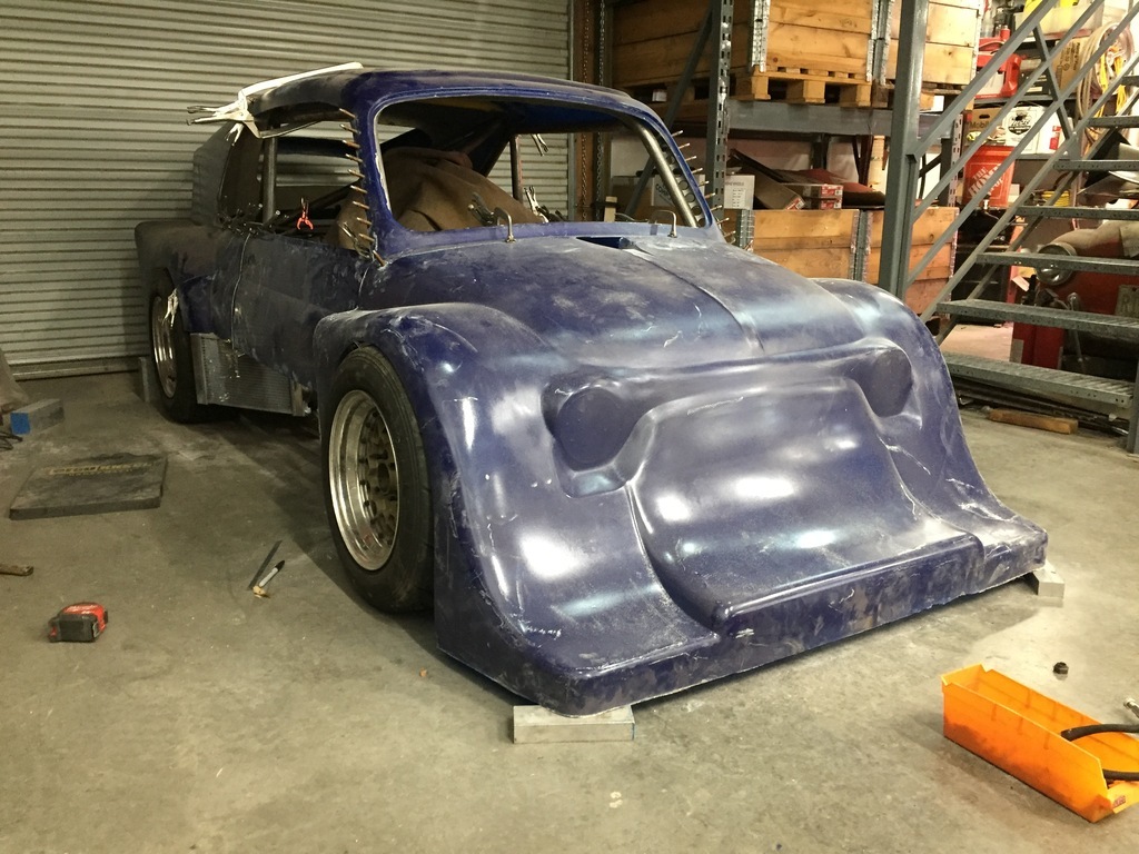
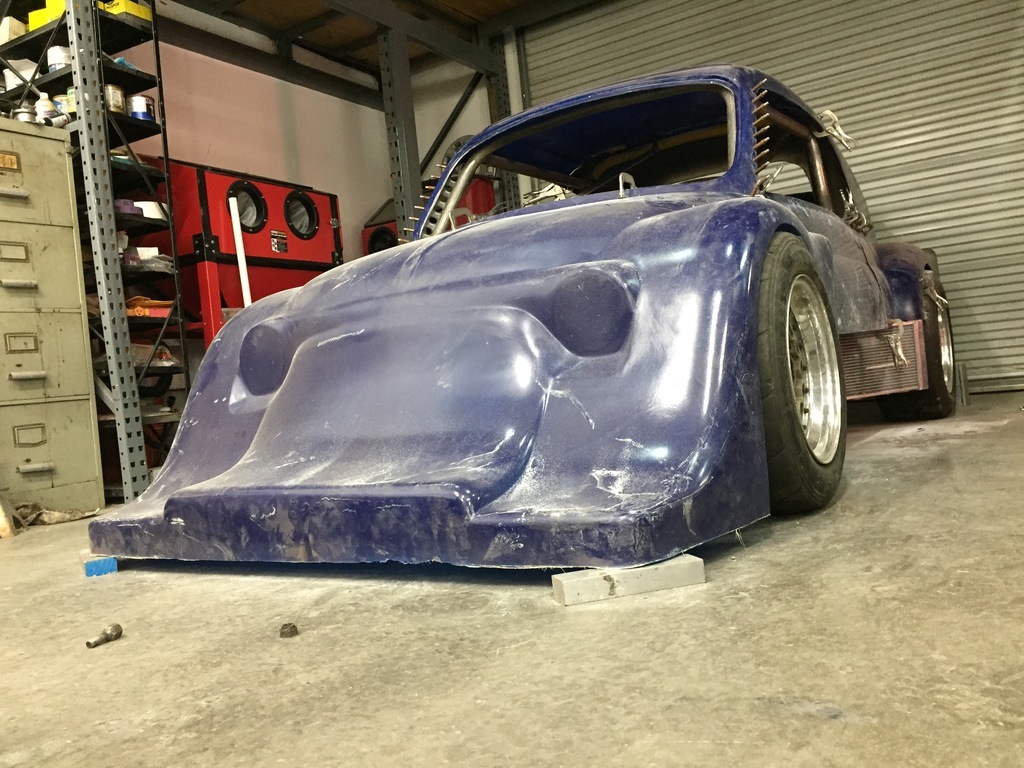
This one has been on hold for a while. I was making good progress, but things stalled when I had trouble getting supplies in the Covid era. So I switched to other projects I already had parts for and/or could get them easier. I wasn't racing anyway, so there no rush to get it done either... But with those projects done & to a good stopping point, its time to pick it back up. Of course, since it was sitting in my workspace and I saw it every day, I didn't stop thinking about it. In fact, it made me reconsider some things. For starters, my choice of wheels & tires. At some point I was able to buy a set of centerlock racing wheels off a Formula ( Atlantic?) racecar very cheap. I was seduced by their extreme light weight, being magnesium, even if the sizes weren't optimal. The 8" rears were good, but the 6" fronts seemed a little narrow. Also by the time I had converted my hubs to fit them ( which took a massive amount of time), a lot of the weight saving was gone... And there is one more practical reason to abandon them. Racing tires ( even when you use DOT type racing tires) are one of the more expensive things on a racer, as far as running costs. Plus, having a fresh set on the racer makes a big difference. So it makes sense (to me) to have one set of wheels fit several cars. The wheels I have for my 1000TC will fit my Mallock with adapters. Today I spent some time to see if I could make them fit the Breadvan 500 as well. All I had to do was replace my fabricated & modified hubs with stock Fiat and Alfa parts ( Fiat 850 based front uprights and Alfetta DeDion rear), to get 4 bolt 98mm hubs on all 4 corners. At which point the 1000TC wheels bolted up. The centerlock wheels had a weird offset, though. So I wasn't sure how that would work out. Its not good, but not as bad as it could be. The front wheels get pushed out by about 3/4" per wheel, the rears by 1". Enough to be a problem with clearance to my brand new/never been on the track body, but not so much its not solvable. The front suspension was built around 10" wheels, and when I last ran it I used 13" with low profile tires to get the right dia.( tires meant for Mini's on 13's with stock wheelwells). Going to the 1000TC wheels gives more wheel width (from 6" to 7" front, rears stay the same at 8"). But the problem is the much bigger diameter front tires. So that means redoing the front suspension. At that time I can take some width out of it, and also convert the front suspension from Metric Heim ( Rose) joints to Inch sizes ( much easier and cheaper to get good quality ones, here) And I think I have worked out how to narrow the rear axle ( some more, I already took 8.5" out of the middle). This is what it looks like on my vintage 3pc Graku wheels. To be honest, I like the look a lot better than the all black ( Dow coated) Technomachnesio wheels... I propped up some (dusty) body panels to see how bad the clearance problem was... 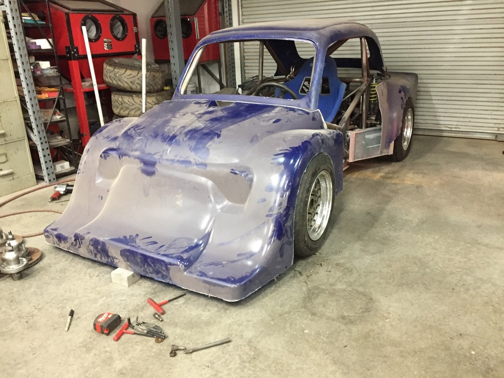 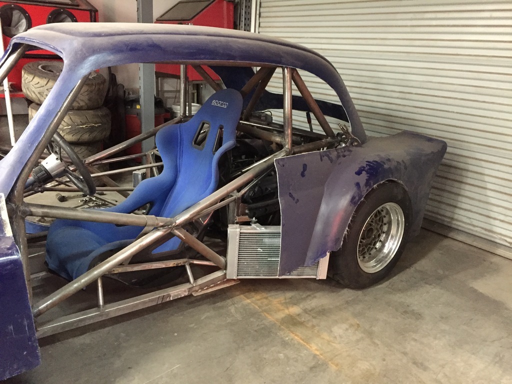 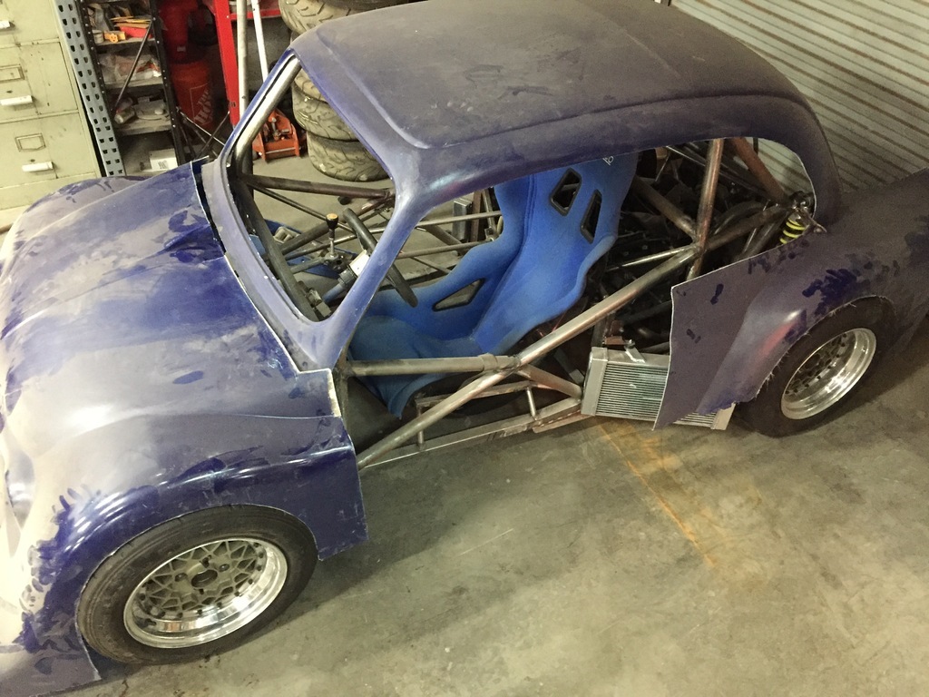 |
| |
|
|
|
|
|
|
|
|
If it wasn't for the body clearance problem, I could live with the extra width.
Maybe I should mount the body panels first, to see how bad the clearance problem really is...
|
| |
|
|
|
|
|
|
|
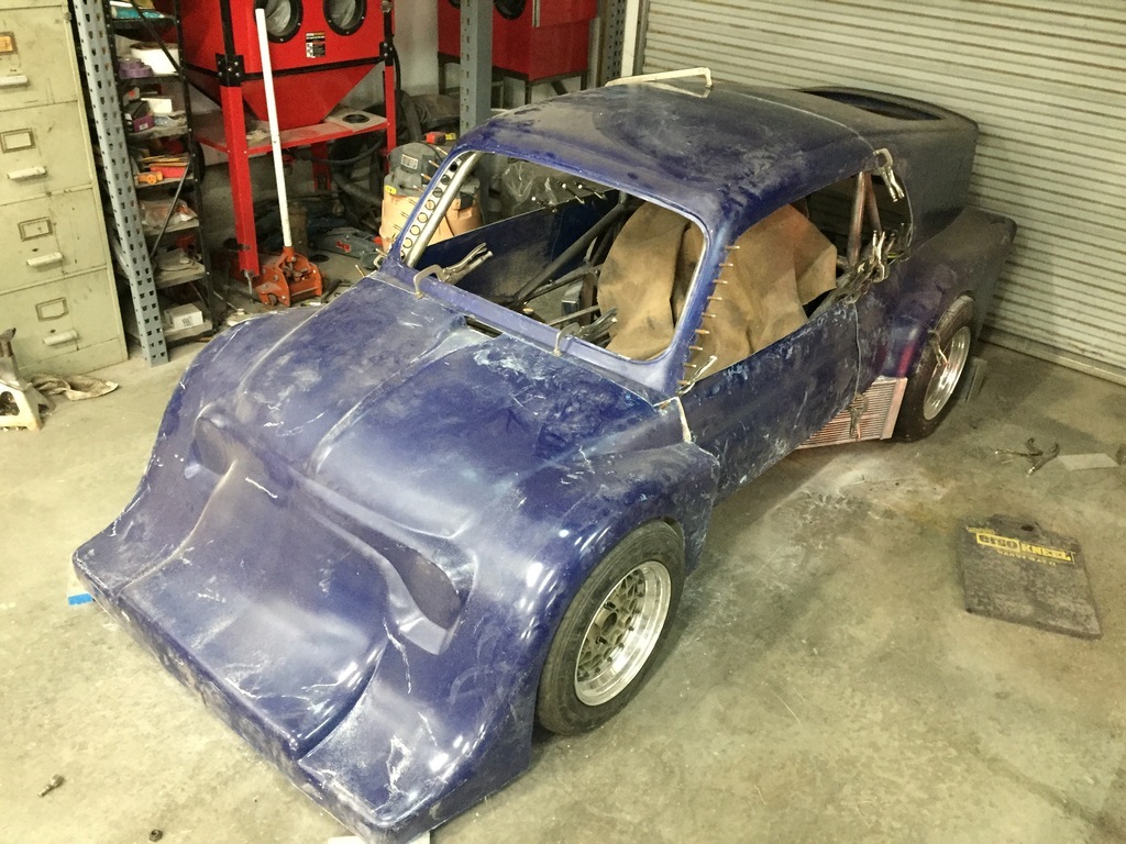
Trying to pick up where I left off. Cant stand back enough to take good pics, but it still gives a idea of where I'm at. ( my main focus will be on the 3W, so that one is in the better part of the workspace). Right now, I'm taking measurements/ making plans ( as far as what needs to be done and in what order), etc. Did some clearancing on the front wheel wells so I can get the body to sit right on the chassis. 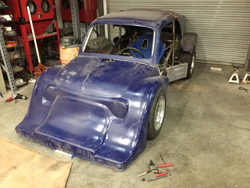 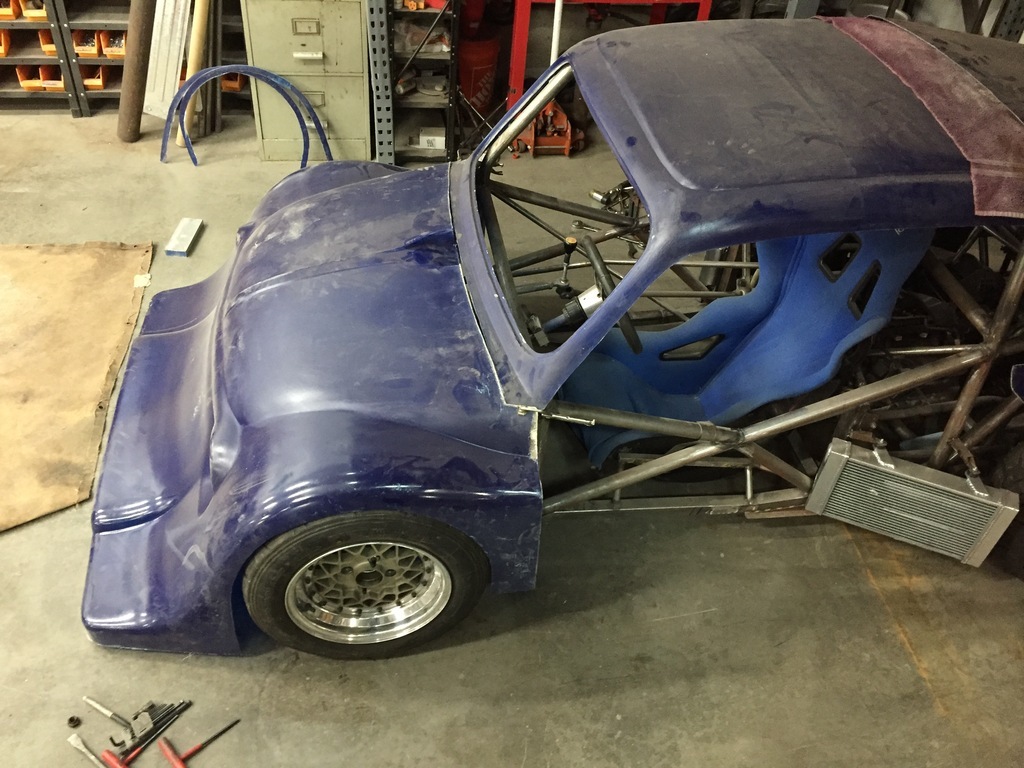 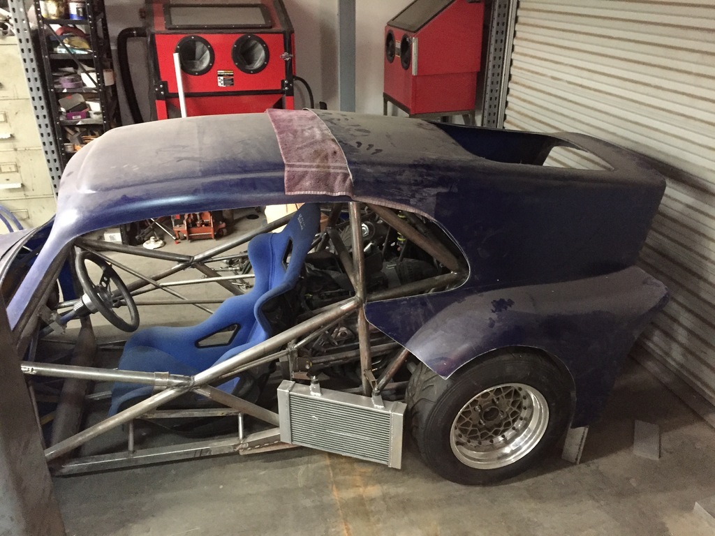 |
| |
|
|
|
|
|
|
|
Mocking up the doors. 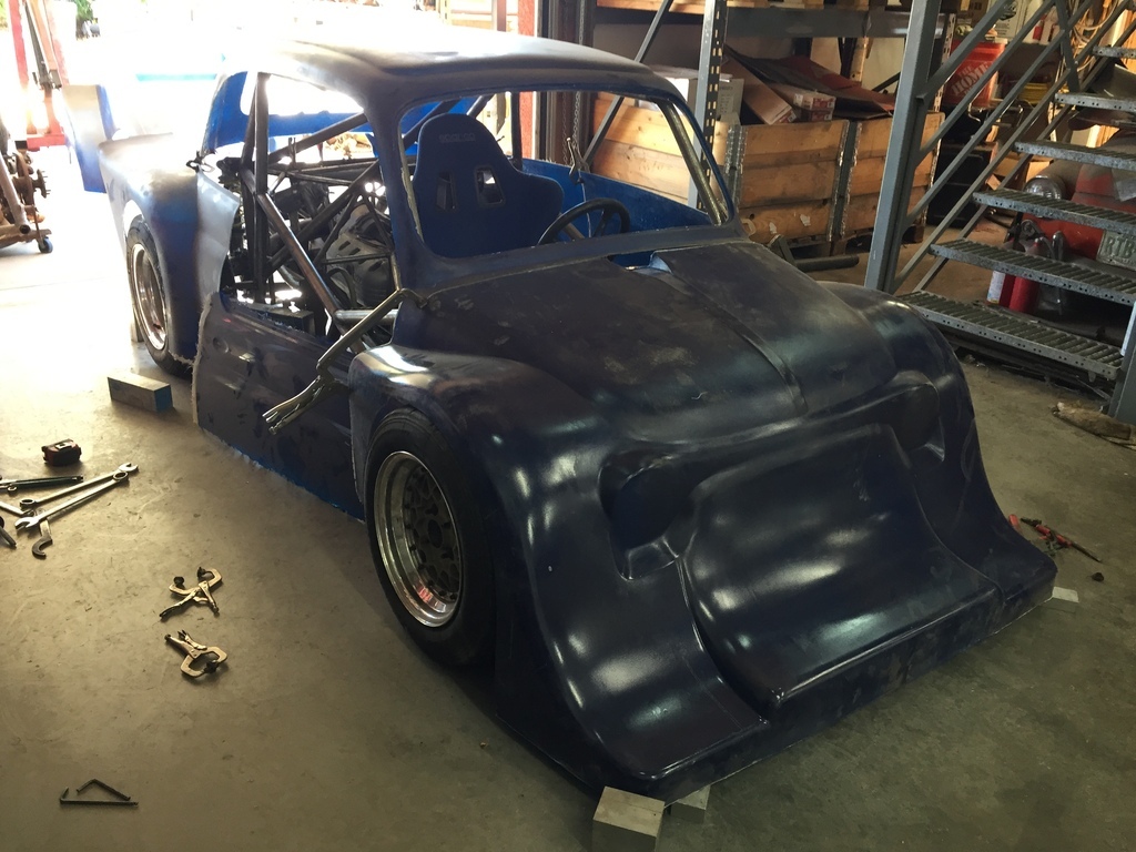 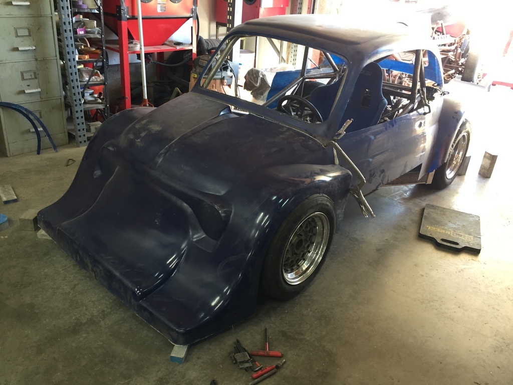 I checked the fit with the original roof shape first.  |
| |
|
|
|
|
|
|
|
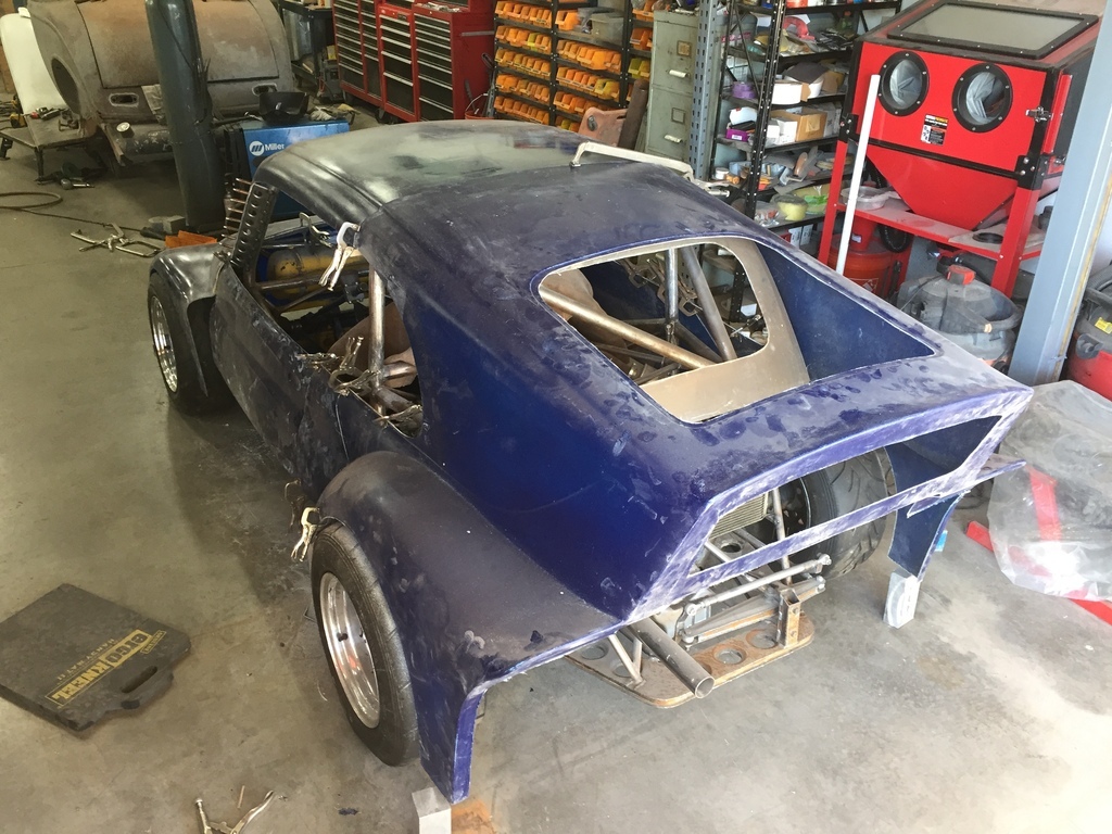
When I had enough information I cut the original shape of the roof ( the back) off the front ( top) of the roof. This cut needed to be kind of accurate, because I want to be able to switch the rear bodywork out. That way I can have the original style body, or the breadvan. So all the shutlines and mounting points need to be identical... I started by making mounting brackets to mate the A pillars to the front of the rollcage. 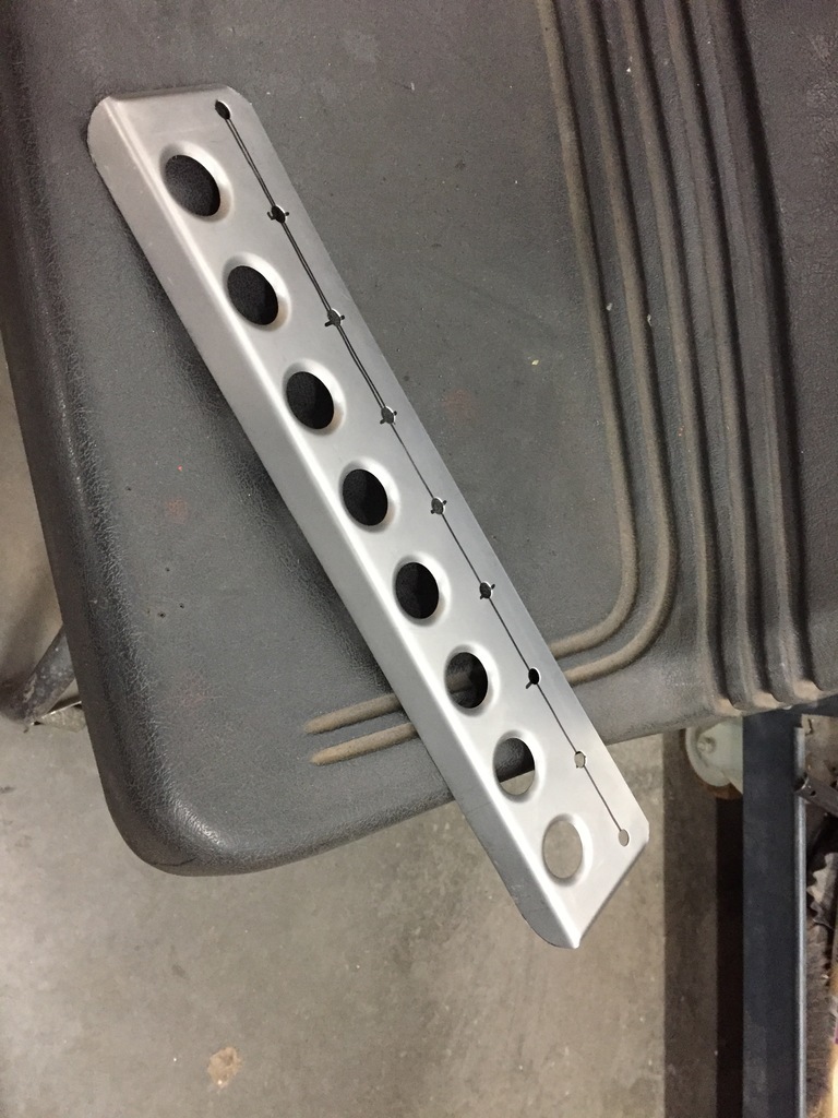 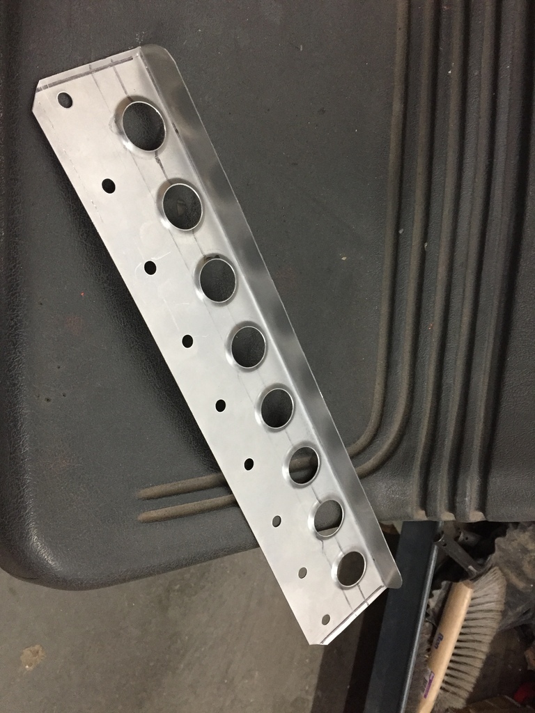 I made a dimple die to finish the lightening holes. Bracket welded in and A pillar held on with Clecos. 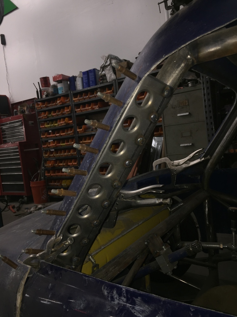 |
| |
|
|
|
|
|
|
|
|
|
That's a cool looking bread van! It's like fiat's answer to the Porsche 935  |
| |
1966 Ford Cortina GT
2018 Ford Fiesta ST
Full time engineer, part time waffler on Youtube - see Jim_Builds
|
|
|
|
|
May 13, 2024 18:04:46 GMT
|
jim, thanks.  I've looked at a lot of cars for inspiration. That one, but also the NZ Anglia Breadvans. 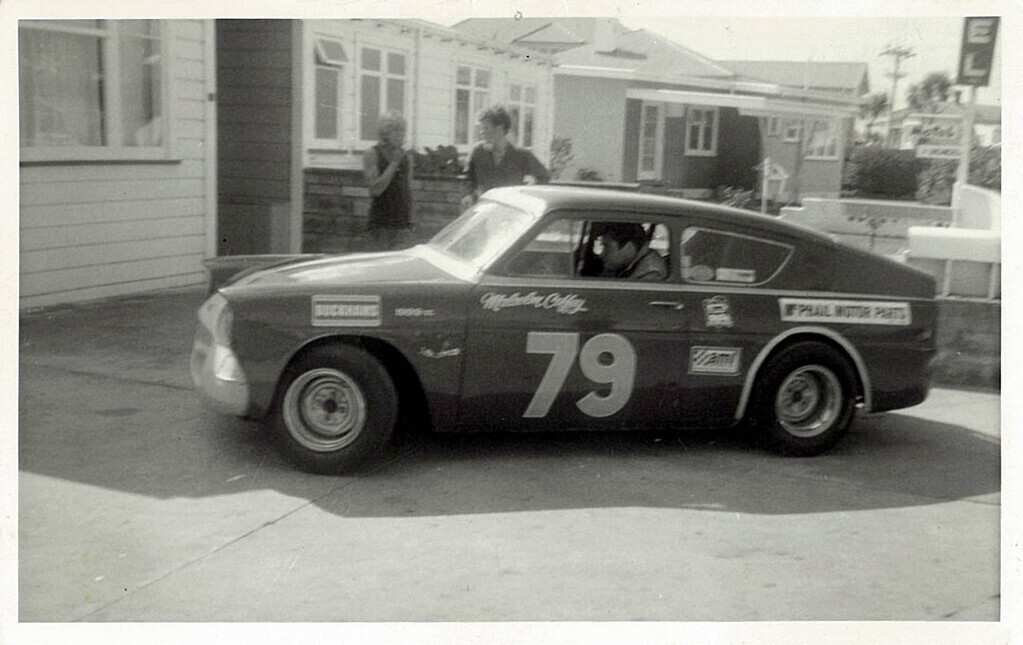 And others. I have a thing for breadvan racers anyway...  I think I can put enough downforce on the back of the car to balance out the front with the OG roofline. But I think with the breadvan roof I might get there in a cleaner/ more efficient way ( aero wise ). In other words, with less drag. That is the main reason I'm building 2 versions for the rear of the bodywork. So I can switch it out quickly at the track, and see what the stopwatch says...
|
| |
|
|
|
|
|
May 13, 2024 19:02:21 GMT
|
I also got the help of a Aero Specialist. I sent him some pencil drawn sketches, and he corrected some obvious flaws he could see. And he told me the maximum save angles for the under body tunnel ( porpoising being the main concern), Etc. I figured hiring him to steer me around some of the basic pitfalls was going to be money well spent... The tunnel starts at 1/2 wheelbase ( which happens to be right at the back edge of the seat), going all the way to the back of the car. With a drop down section around the transmission. I worked out the placement and dimensions of the tunnel first, and designed the rear suspension around that. ( the goal was to have no linkages interfering with it). The rear suspension is a DeDion ( modified Alfa Romeo Alfetta), with a 4 link based on a aftermarket Escort Mk1 kit, and sideways location is my own design ( that will be interesting to see if it works...  If it doesnt, I'll replace that with a Mumford Link ) The transmission ( transaxle) is a Hewland Mk9. |
| |
|
|
|
|
|
|
|
May 20, 2024 19:14:02 GMT
|
When I modified the chassis for the K1200RS engine and Hewland gearbox I also changed the lower part of the cage. Specially in the lower A-pillar area, so air would have a easier/ more natural path out of the front wheelwell. And I left the lower part of the body sides off when I made the new body in fiberglass, also for aero. So now it was time to figure out what it all was going to look like... In cardboard & wood ( later to be replaced by aluminum sheet). 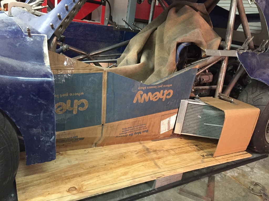 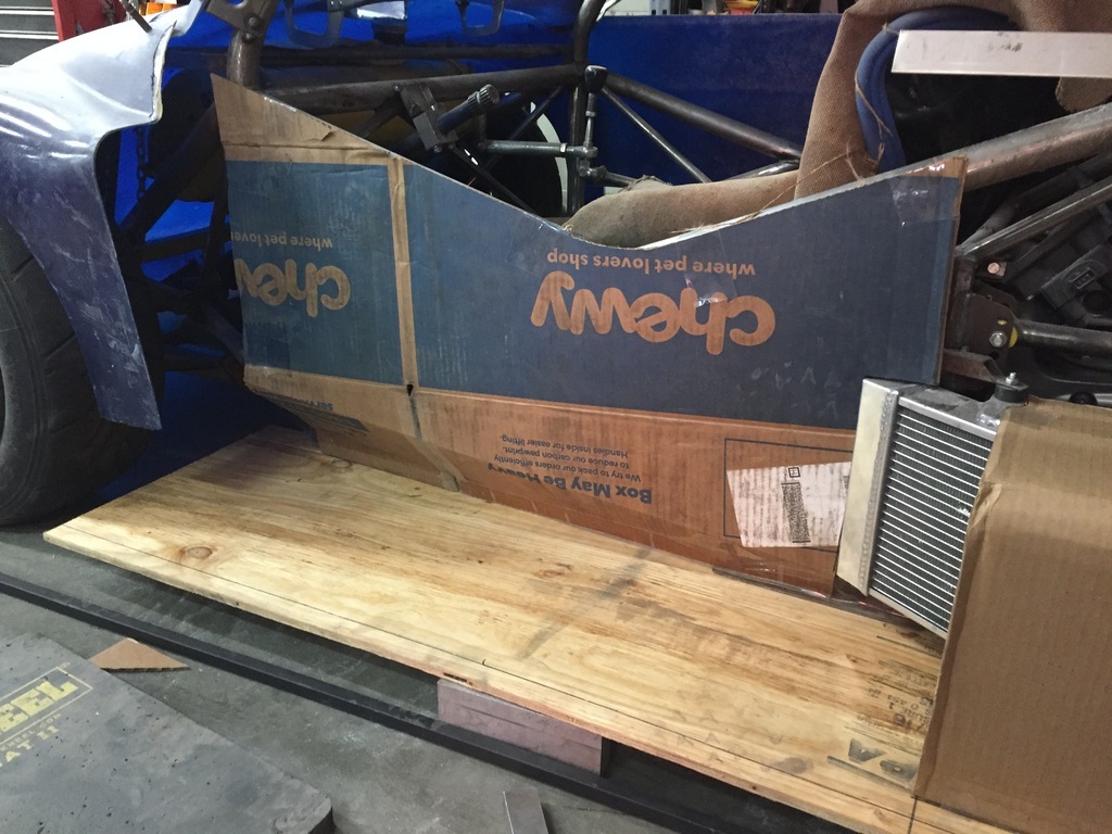 I think the engine compartment is going to be a low pressure area. The Kamm Tail is open at the back, so I figure when the car is moving the wake is going to try and draw air out of that area. I want to draw as much air out of the front wheel well as possible ( in a earlier version air got trapped onder the front of the car, it did better laptimes without the 1 piece nose). Since there is quite a bit of space between the side of the cage and the inside of the door, I think is makes sense to connect those 2 areas. To allow the low pressure in the engine compartment to draw some volume of air and pressure out of the front wheelwell. If it works, great. If it doesnt, its not a lot of weight so no harm done ( and it will help as a deformable structure in case of a side impact...) 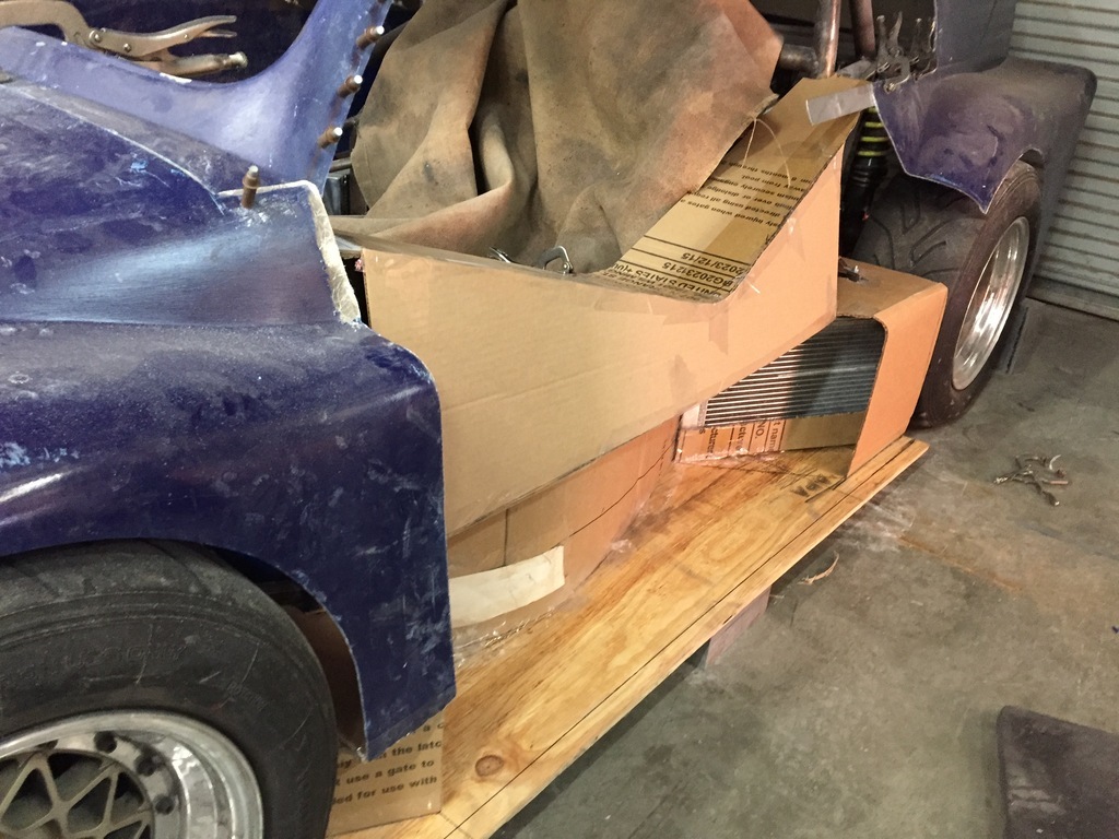 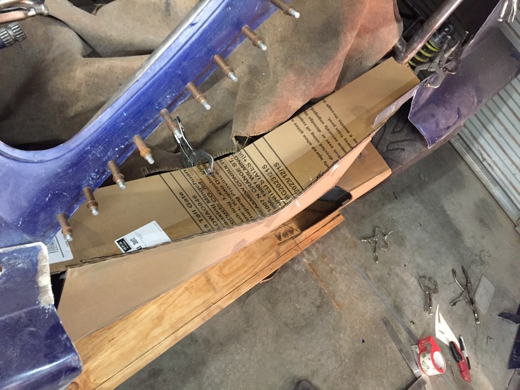 Under the tunnel is the rounded shape that will hopefully help drawing air out of the wheelwell, and guiding air to the side radiator. 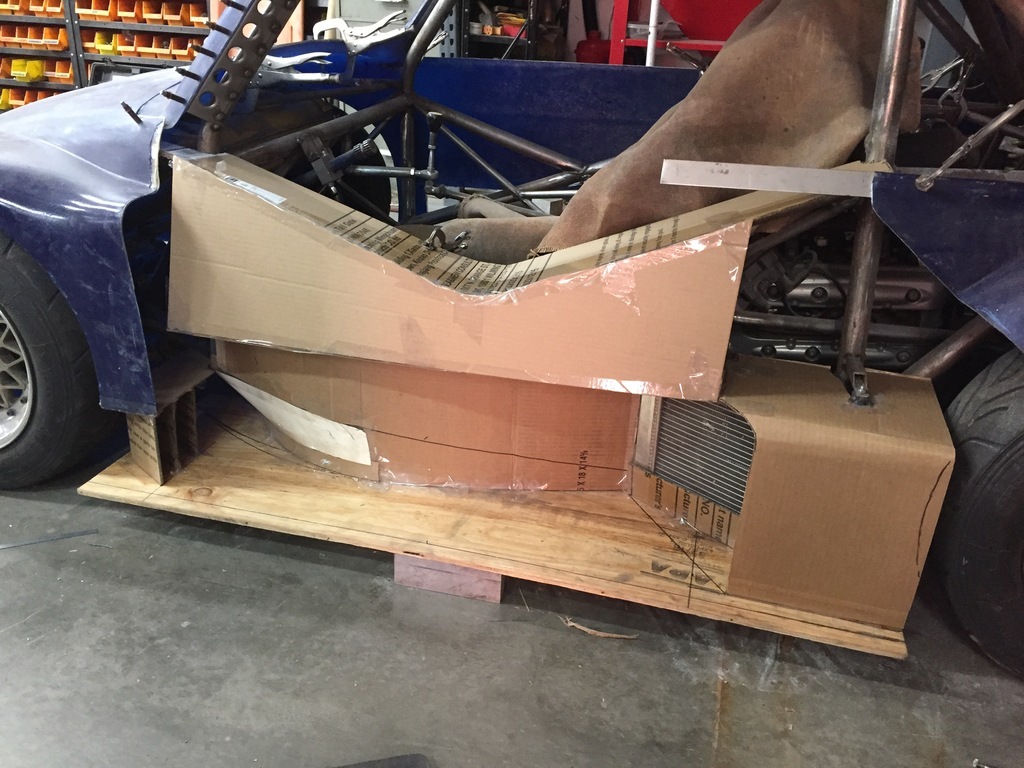 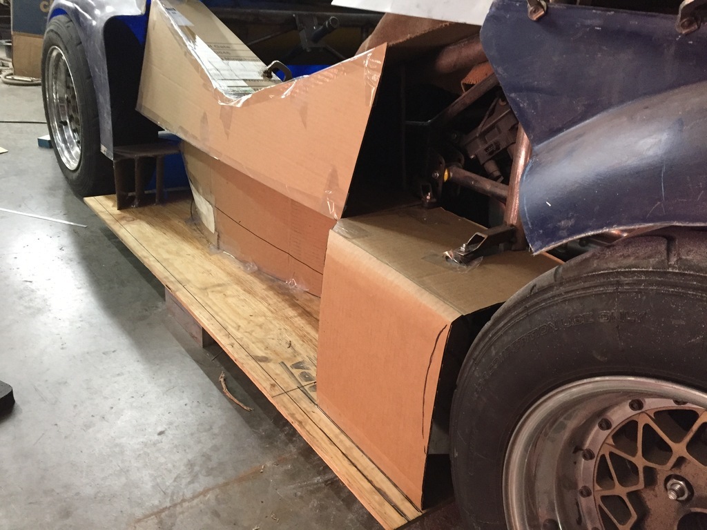 About what it will look like with the doors and the rest of the body in place. 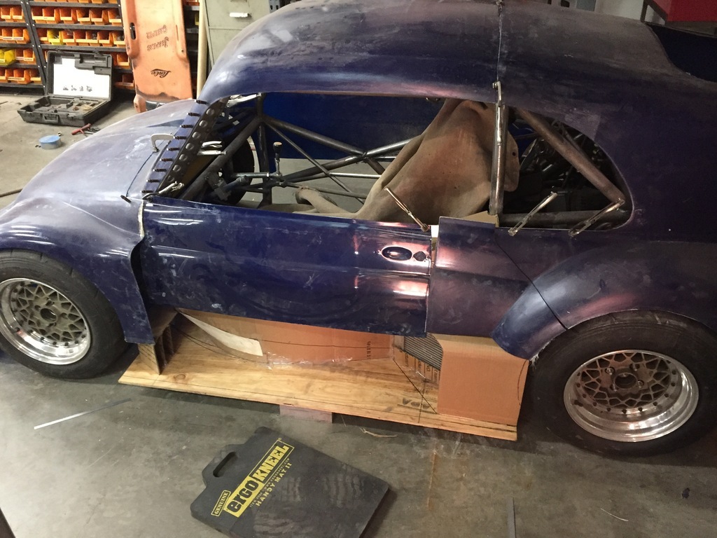 |
| |
|
|
|
|
|
May 20, 2024 19:16:39 GMT
|
More mock up. Rear wing ( not mine, I'll have to find one, or build something myself). 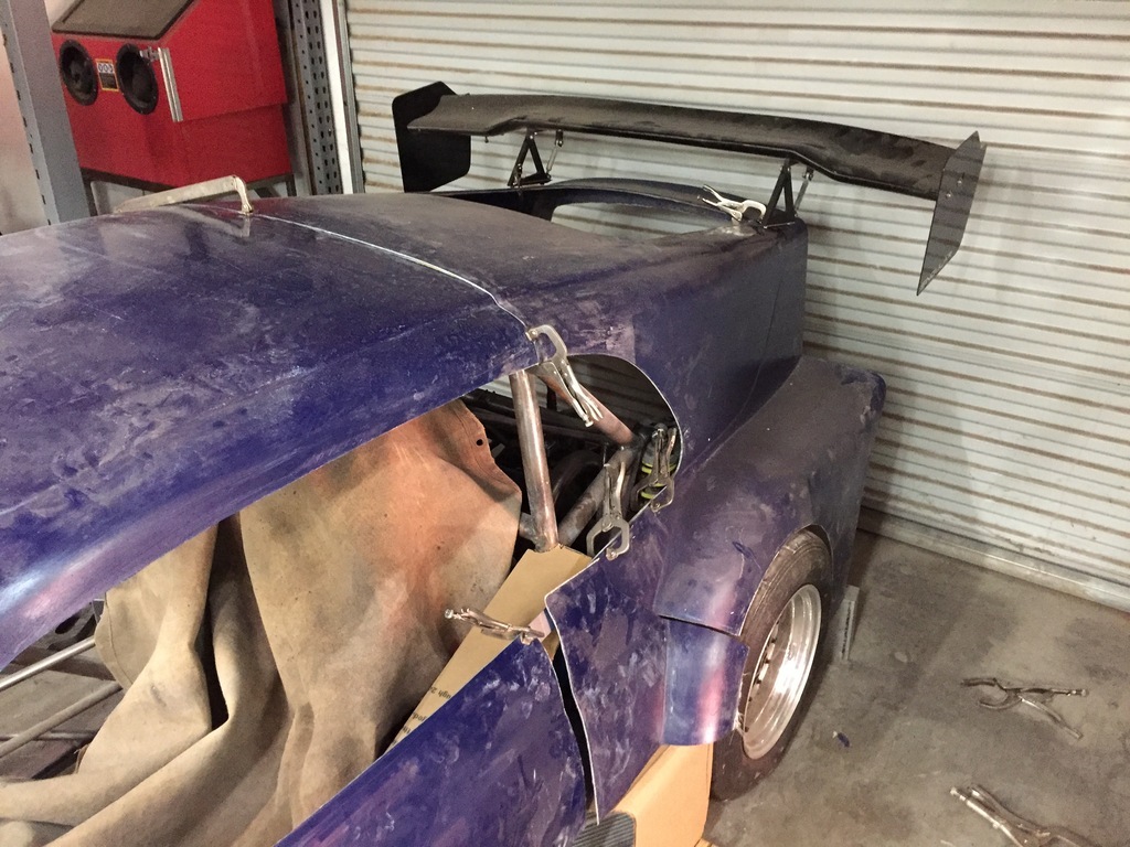 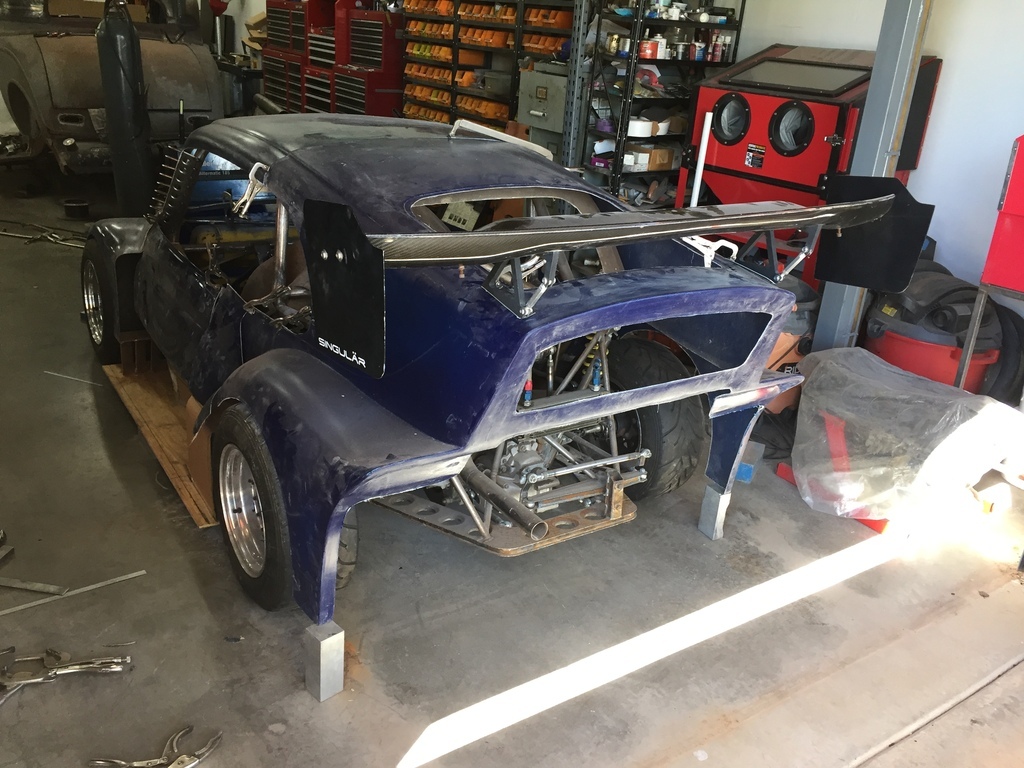 |
| |
|
|
|
|
|
May 20, 2024 19:21:05 GMT
|
Cut the nose at 3" of ground clearence and put in a temporary (plywood) splitter. 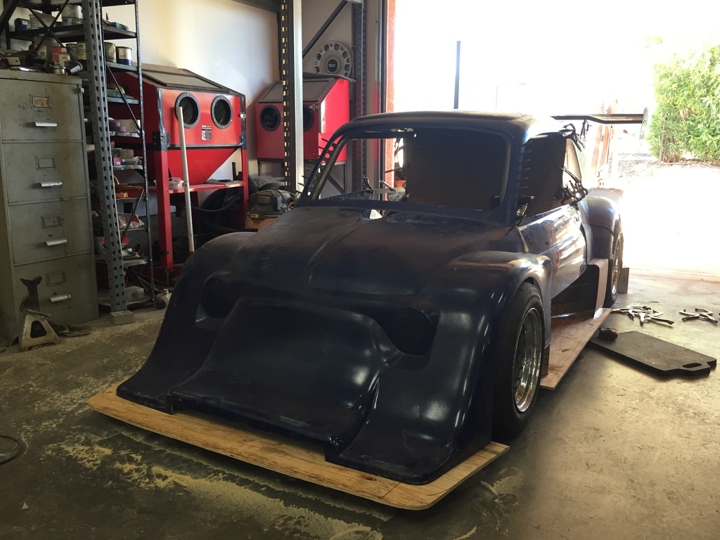 And I started to try and figure out the firewall between the driver compartment and the engine compartment. 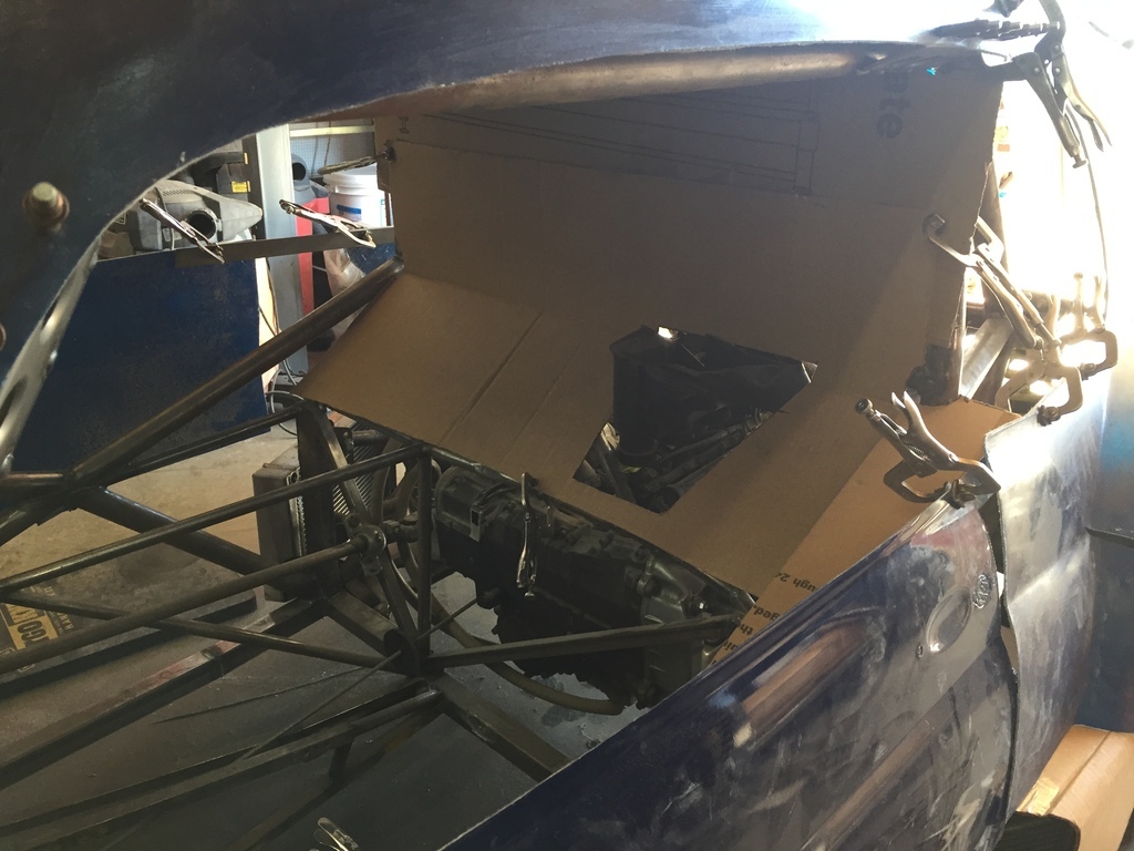 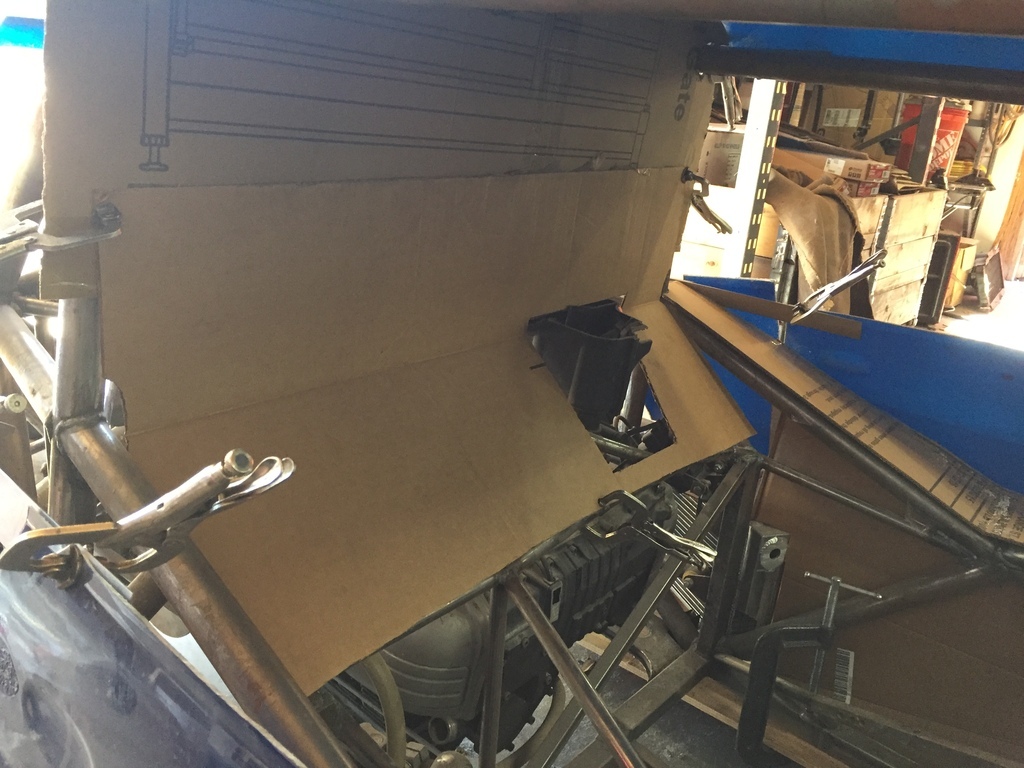 |
| |
|
|
|
|
|
|
|
|
|
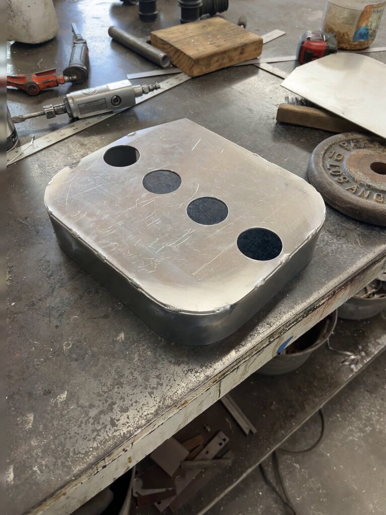
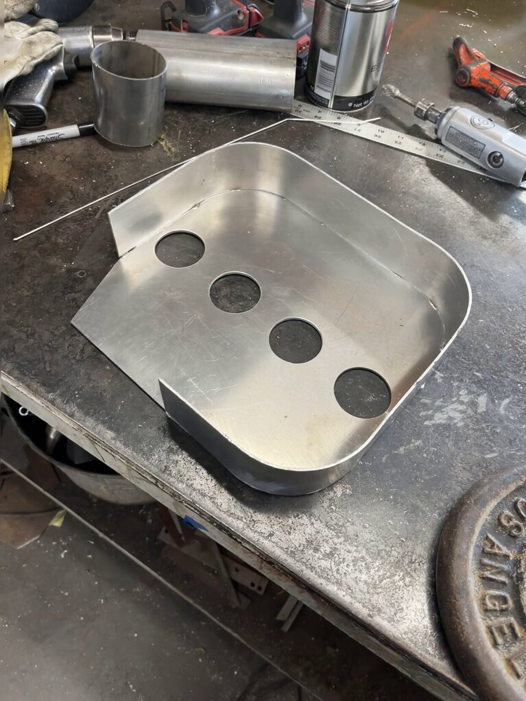
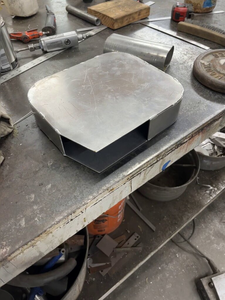
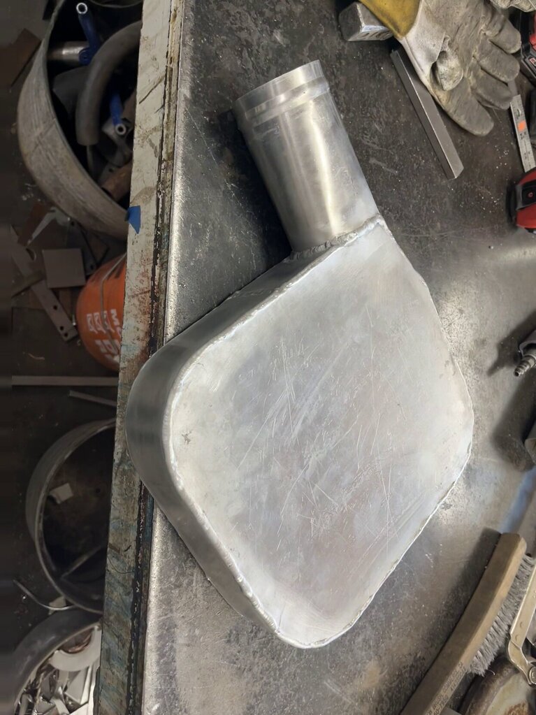
Mounted in the car ( it will need a couple of brackets to hold it in place, but I can do those at a later date ). 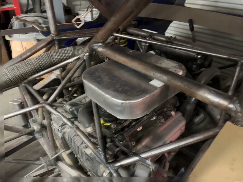  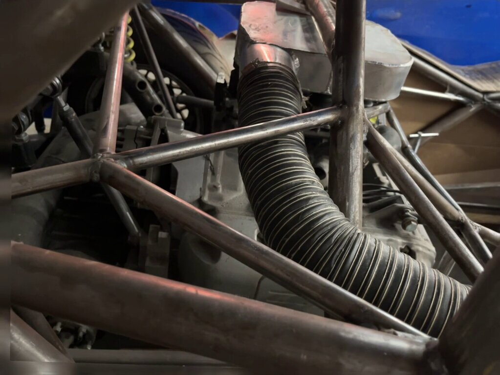 The hose will go through the firewall, along the side of the cockpit. To another plenum (still to be made) where the dash used to be. It will basically be a pressure box that will be fed from the NACA Duct at the base of the windshield. That will be a high pressure point of the bodywork ( it will basically be cowl induction), so that should give some ram air to the engine. 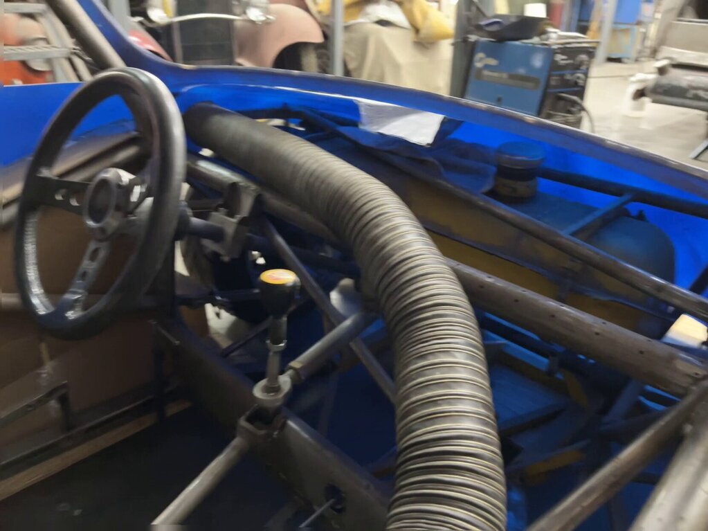 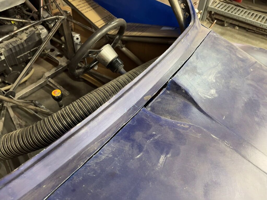 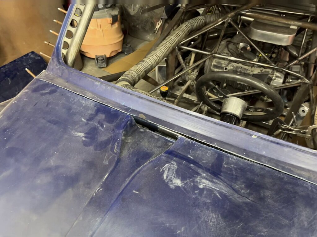 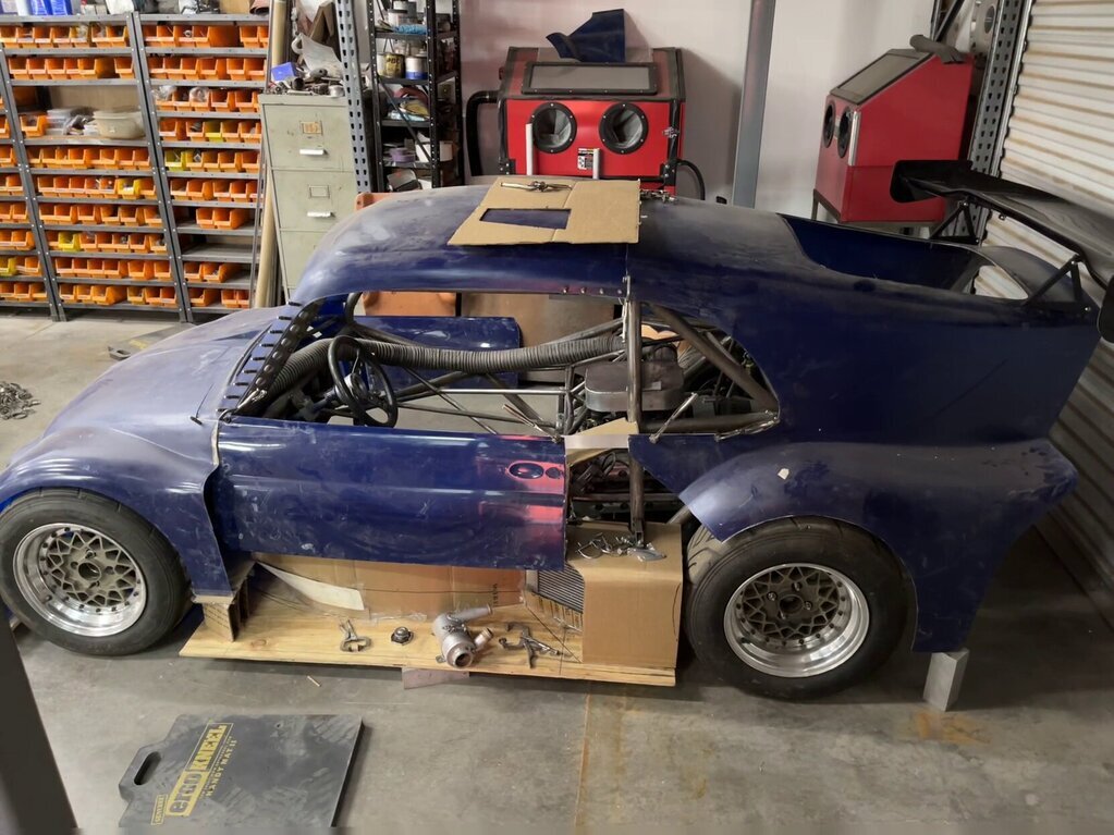 |
| |
|
|
|
|
|
|
|
I started to hang the back of the body. 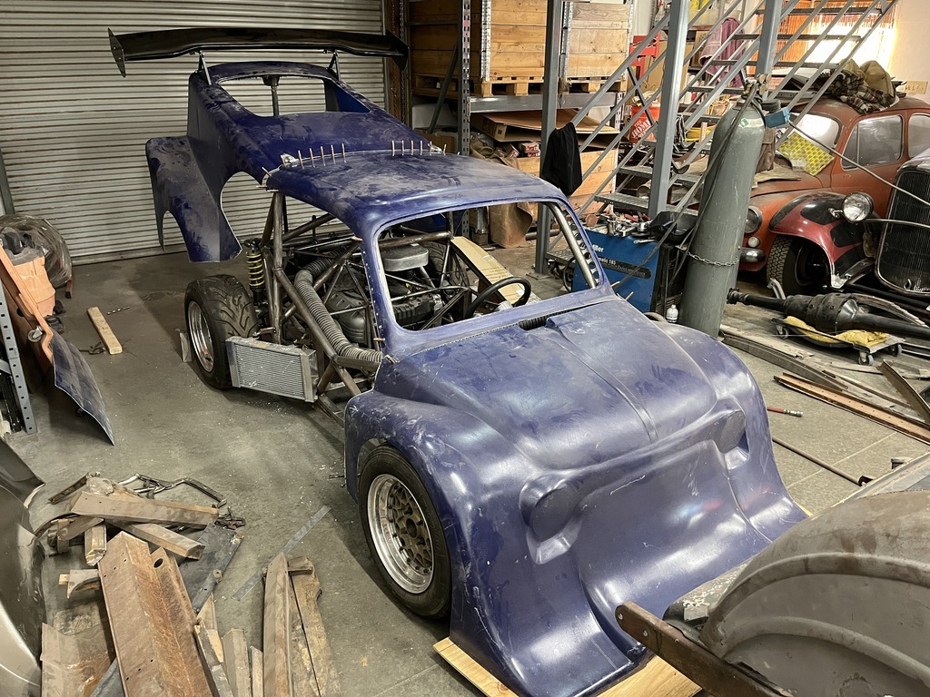 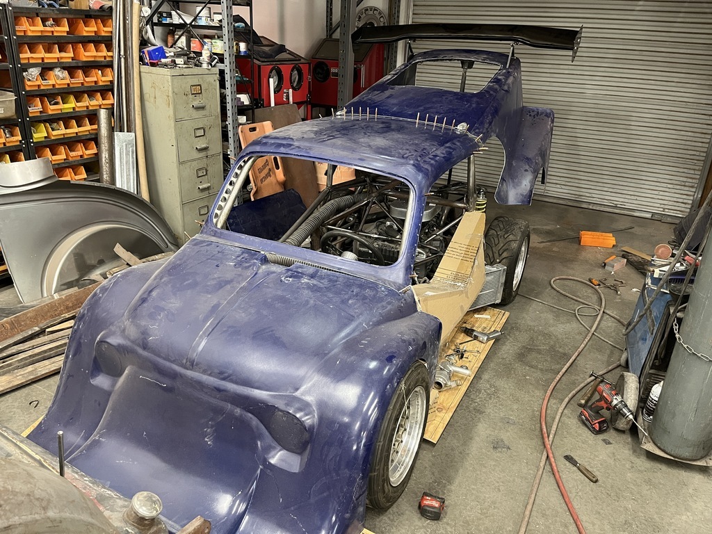 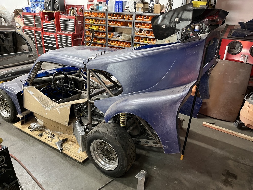 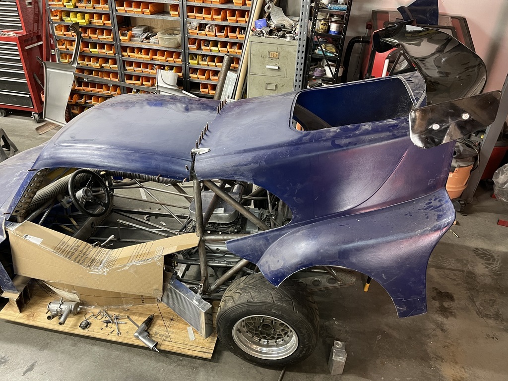 I'm using aero hinges a buddy of mine did on his homebuilt CNC. 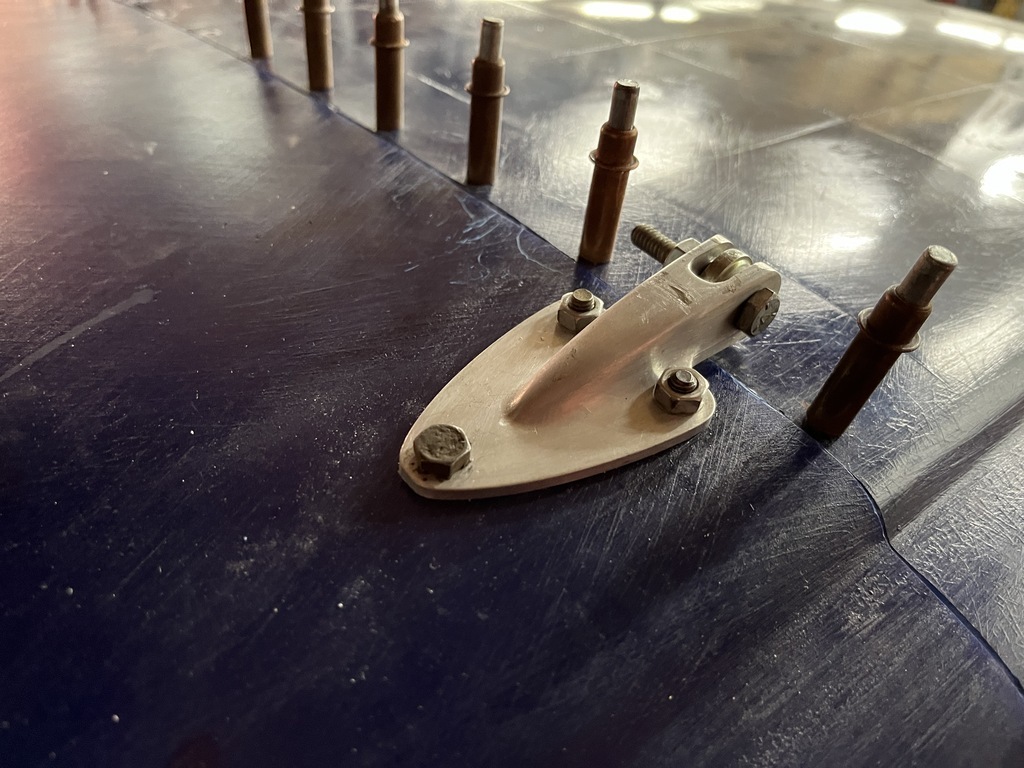 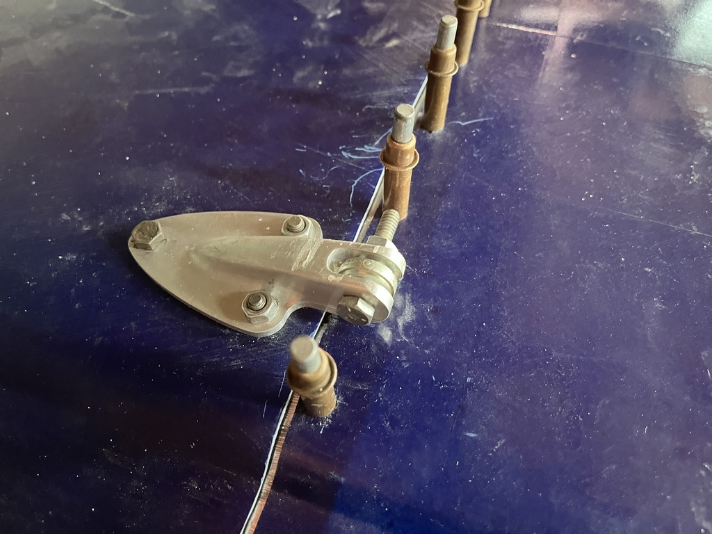 BTW, Because I need a couple more of those hinges him and me were talking about doing a small run of them. And possibly selling them on Ebay, or similar. Seems to me, there has to be a need for hinges like these... So he made a mold to cast them. The aluminum piece bolts to the panel, and use a 1/4" Heim ( Rose) joint as the pivot point ( for strength, easy alignment, and adjustability). If they look like something you can use, let me know and I'll get you in touch with him. |
| |
|
|
|
|
logicaluk
Posted a lot
   Every days a school day round here
Posts: 1,373
|
|
Jul 12, 2024 11:37:59 GMT
|
|
Those hinges are very nice, wouldn it take much to mount them under the panel for extra aero and cool points?
D
|
| |
|
|
|
|
|
Jul 12, 2024 18:56:13 GMT
|
Those hinges are very nice, wouldn it take much to mount them under the panel for extra aero and cool points? D No, the pivotpoint needs to be above the surface enough so the back panel clears the dome of the roof, when it opens. To make a hinge that sits under the panel that does that would mean pushing the pivot point forward so far it would extend into the drivers compartment. Which is cramped already... Also, I like the simplicity of the externally mounted hinges. All I need to do is pull the hinge pins out ( which I can do with the panel closed) and the rear panel is loose, ready to be lifted off. The front of the body will be lift off as well ( but without hinges), and also the doors. Being able to remove panels quickly like that is a huge timesaver when the car needs to be worked on ( between race days, or even at the track...) |
| |
|
|
logicaluk
Posted a lot
   Every days a school day round here
Posts: 1,373
|
|
Jul 12, 2024 21:22:50 GMT
|
|
I was meaning lengthening the rib, so the flat plate could be bolted on from underneath, leaving the hinge point as is.
|
| |
|
|
|
|


