bstardchild
Club Retro Rides Member
Posts: 14,901
Club RR Member Number: 71
|
|
|
|
Bloody hell fire! Incredible stuff. Speechless - which is just as well really as there's only me and the dogs here at the moment, so I'd be talking to myself. And we all know where that leads.  Just thinking though, if you keep gluing and bolting more bits on, you'll be needing a bigger engine soon, that'll mean moving everything around again, sticking some more bits, even bigger engine, more stuff...  Nah - you don't need a bigger engine - Honda already covered that - they did a CX650 so 150cc bigger and if that's not enough 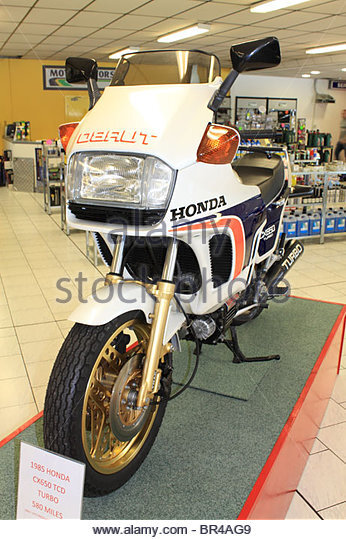 So a snail should fix it |
| |
|
|
|
|
|
|
|
Nov 19, 2017 11:50:29 GMT
|
Bloody hell fire! Incredible stuff. Speechless - which is just as well really as there's only me and the dogs here at the moment, so I'd be talking to myself. And we all know where that leads. Just thinking though, if you keep gluing and bolting more bits on, you'll be needing a bigger engine soon, that'll mean moving everything around again, sticking some more bits, even bigger engine, more stuff... Hi George, the only trouble with talking to yourself is most of the time you know wht your reply is going to be It's funny, before I added the 4 wheel drive stuff MadTrax looked all engine and fuel tank.. Now it's in 4 wheel drive mode the engine and fuel tank look small! Bloody hell fire! Incredible stuff. Speechless - which is just as well really as there's only me and the dogs here at the moment, so I'd be talking to myself. And we all know where that leads. Just thinking though, if you keep gluing and bolting more bits on, you'll be needing a bigger engine soon, that'll mean moving everything around again, sticking some more bits, even bigger engine, more stuff... Nah - you don't need a bigger engine - Honda already covered that - they did a CX650 so 150cc bigger and if that's not enough So a snail should fix it A turbo 650 engine would be nice (I do need the sound of a turbo in my life ) I'm not sure the rest of the drive train could handle it seeing as they are.. How do I put this... Er.. Cheap Chinese! Saying that, when I cracked open the rear axle drive unit everything looked in very good shape despite the abuse it had had in the hands of previous owners! While waiting for the bearings to turn up, I thought I'd make a start on a sleeve to fit over the input shaft on the TB.. The only bit of steel bar I have which is long enough is made from very hard steel and looks like it has been used to hold a JCB bucket on... That sort of hardness! Anyway, I can make it in two parts and weld them together which would make it easier turning the tapered part half way down the shaft inside.. These two lumps I made years ago as pivot points for a dozer blade that was going to go on the 6x6.. A lot of turning to get them down to size! At least one is mostly done 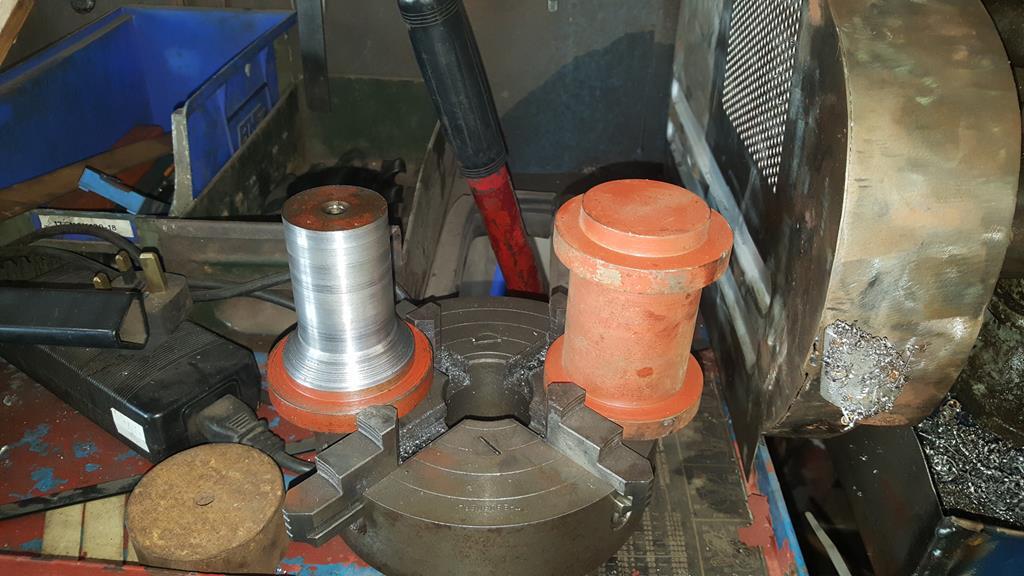 Woo Hoo... The bearings arrived  Here's the TB to front end bearing mocked in place.. 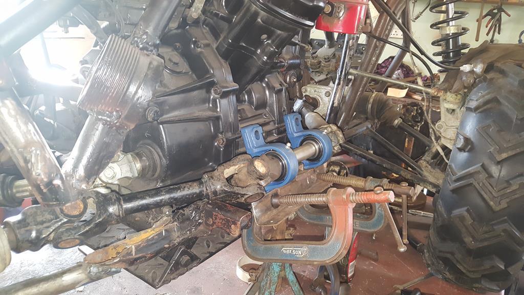 Best start getting the bearings mounted then.. First up something to bolt them to.. Well, a couple of somethings.. 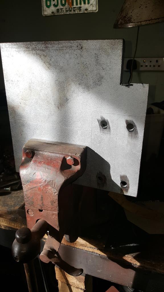 Bolted on. The black bit of steel across the lower bearing bolts is just to keep the bearing square to each other. You can just see where I welded on some tempoary bracing to the drive shaft to stop anything moving about withough the axle stand and other bits that were holding the bearings etc in place. 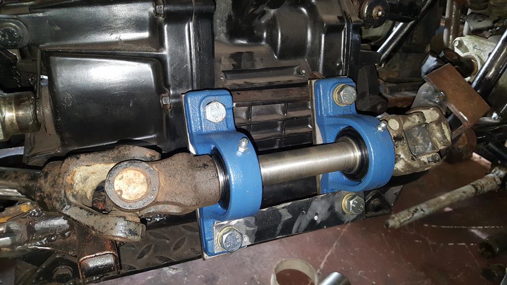 If you flip the bearings over you can see the captive nuts that have been welded on... Don't think they are going anywhere 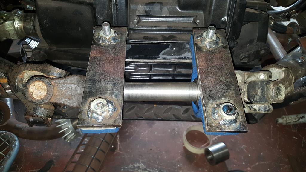 Now the fun bit.. Making four somethings to bridge the gap between the back of the bearings and the chassis/frame.. 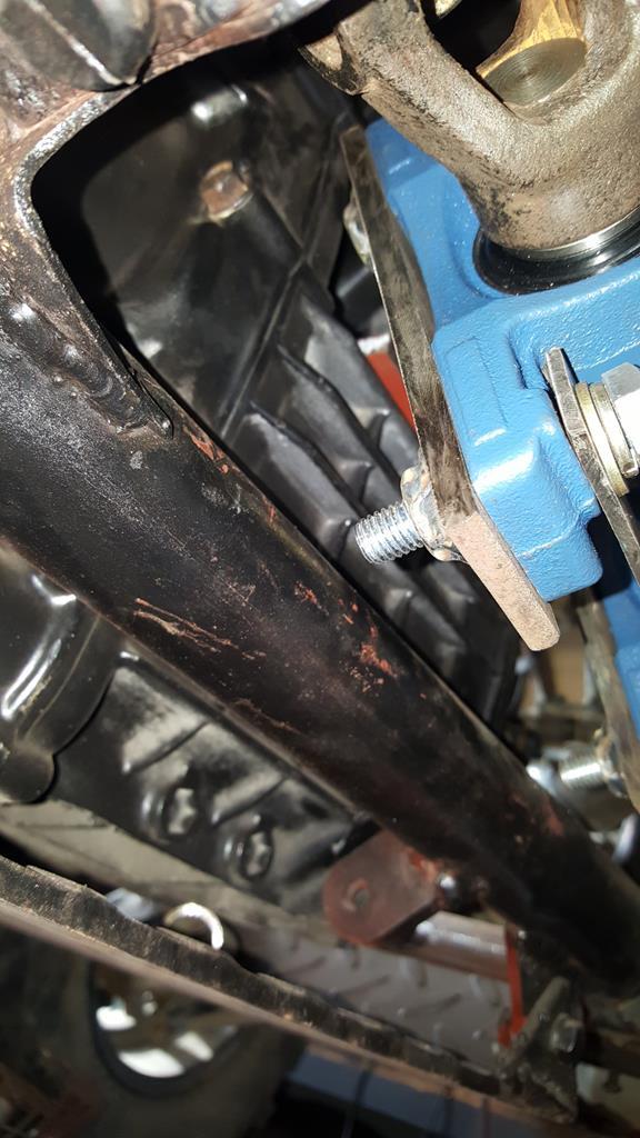 Starting with a bit of CAD (cardboard aided design) work.. 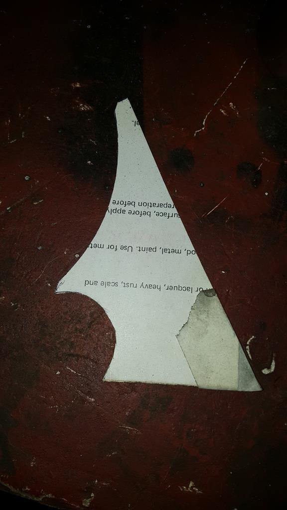 Which goes somewhere here.. Rather hard to hold it in place and take a farto at the same time! 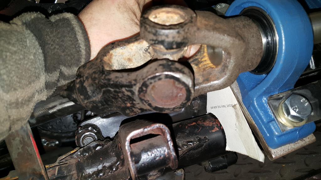 Roughly cut out of steel.. 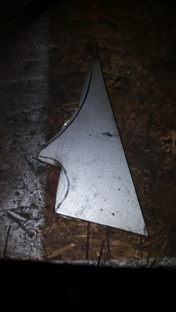 That looks better. 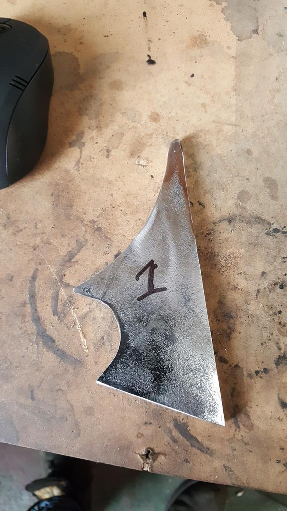 Four of em made and tacked in place.. 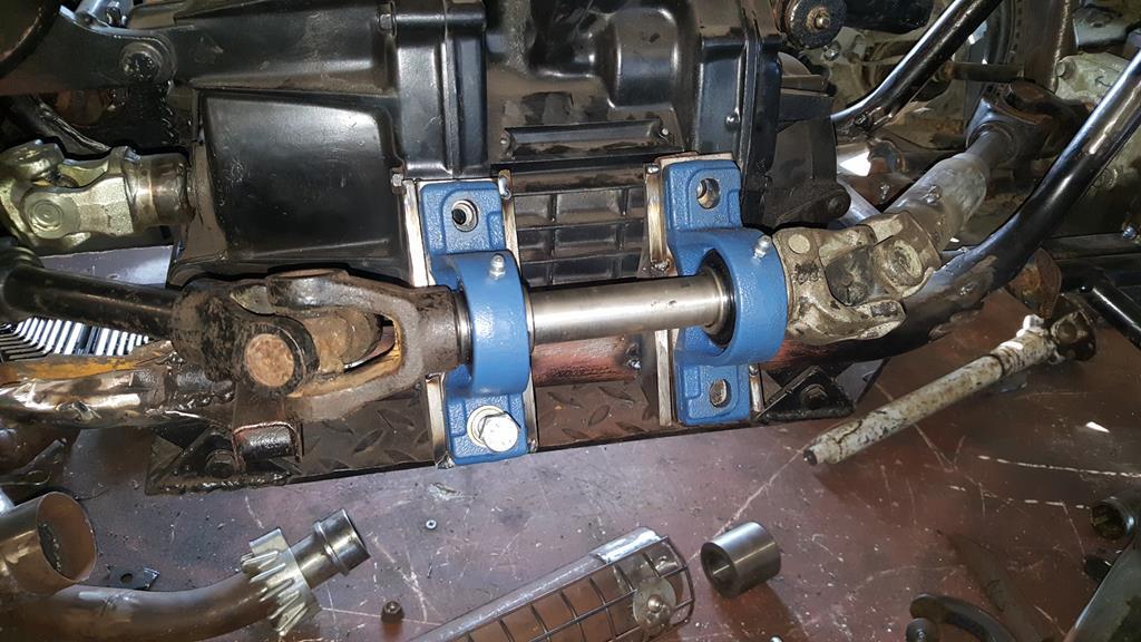 Bearings off.. 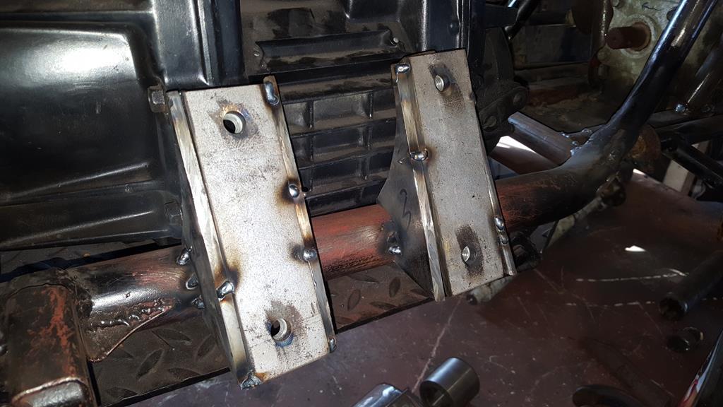 Fully welded up... Almost.. It will be easier to weld the extreme top on bottoms where the brackets fit on the frame without the engine in and sump guard in place, so that can wait until stripdown time. 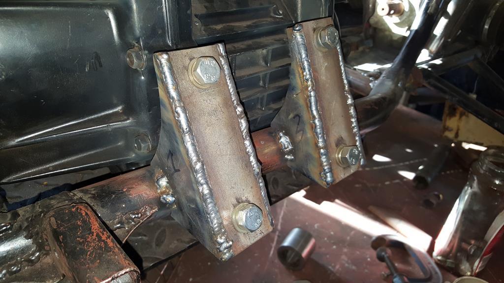 Welds ground down, a nice curve at the back to clear the engine. 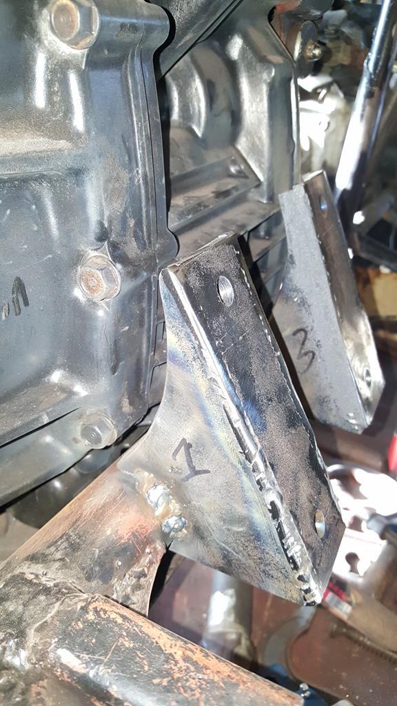 And most importantly, there is still plenty of UJ clearance here and here  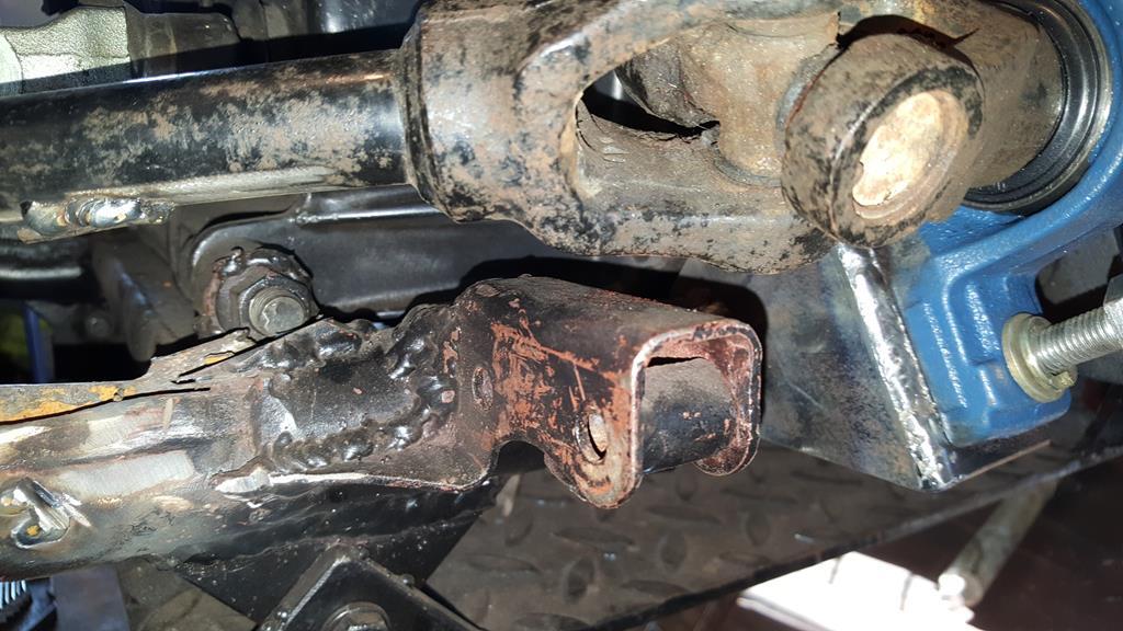 The bearings etc quickly bolted on for this very photo.. The mounts were still very hot from welding and grinding so I didn't want the bearings sitting getting hot for too long.. 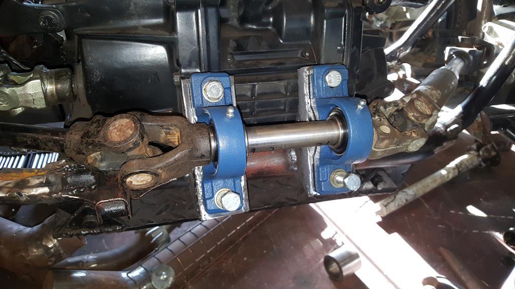 |
| |
My YouTube Channel www.youtube.com/user/UkWheelHorseBlokeQuote - D'you know, it's people like you, doing totally brilliant and pointless stuff like this that gives me a little hope for humanity |
|
|
|
|
Nov 19, 2017 12:17:15 GMT
|
Front drive shaft welded up, I don't think it will be going anywhere anytime soon 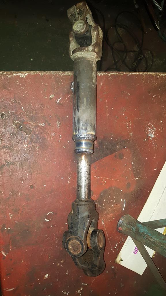 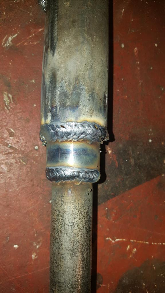 And then it was pointed out that I had welded the shaft up with the UJ's out of phase!! Oh well, I also had a slight length problem as something had moved during welding, so in the vice the shaft went to have a weld cut down. 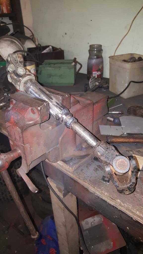 Welded back up at the right length with the UJ's in phase 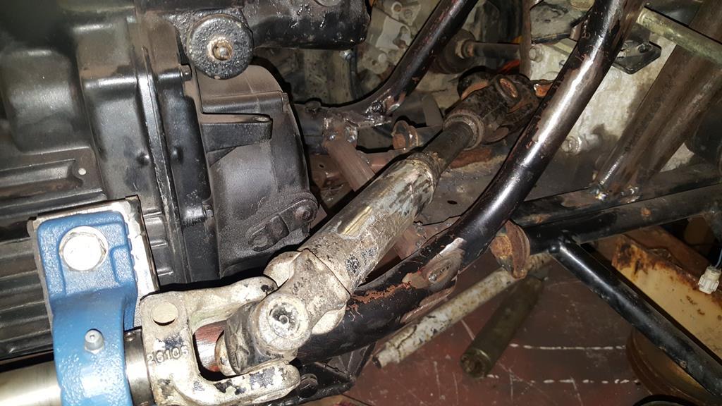 The front shaft out the TB is way too hard to drill, so the UJ is held on with a couple of grub screws.. I will add a couple more for peace of mind.. 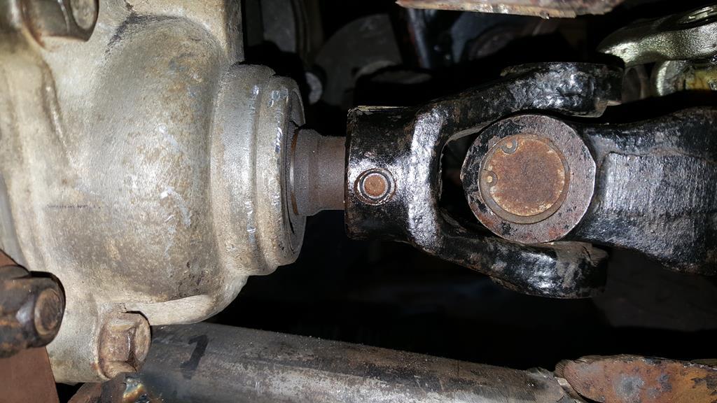 The UJ's that fit on the shaft with bearings are a very tight fit on the shaft, so I drilled them out to fit some nice tight roll pins.. The bolts are only there at the mo to make it easier to take things apart (many times) during building and will be replaced with roll pins.  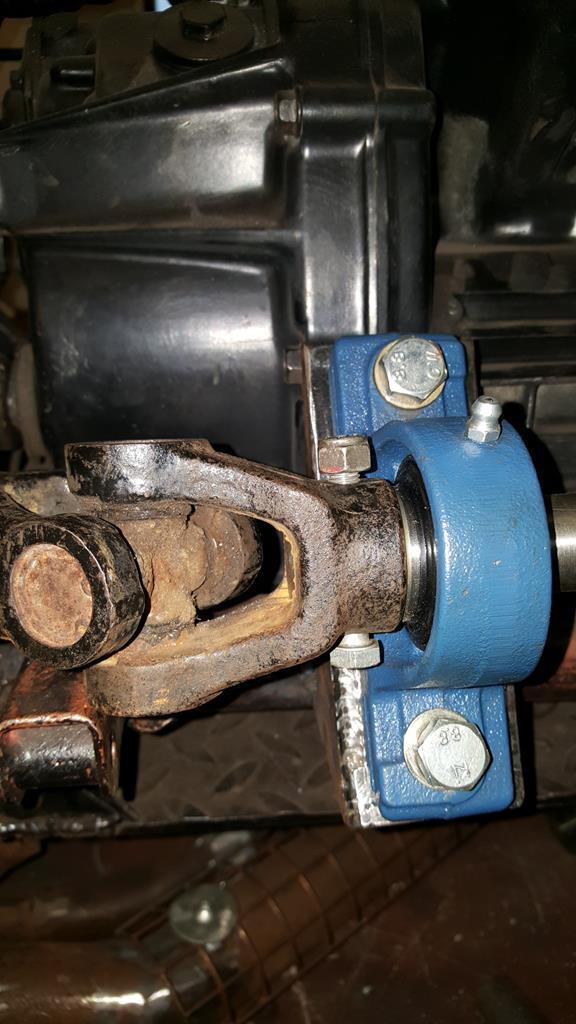 One of the UJ's being a MAN steering coloum UJ is normally held onto a shaft with a nut and bolt one side.. Fine if it's being used for steering but as it will be turning a lot faster it would of been out of balance! My solution was to cut most of the clamping bit off but leave enough to get a bolt through and clamp it tightly. (The drill bit is only there to line the holes up for putting a roll pin through. 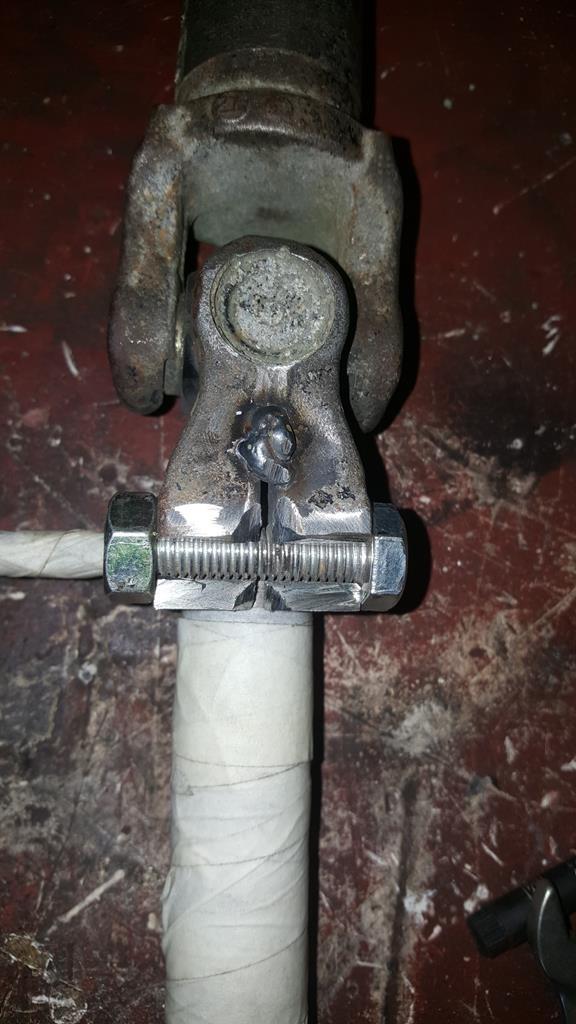 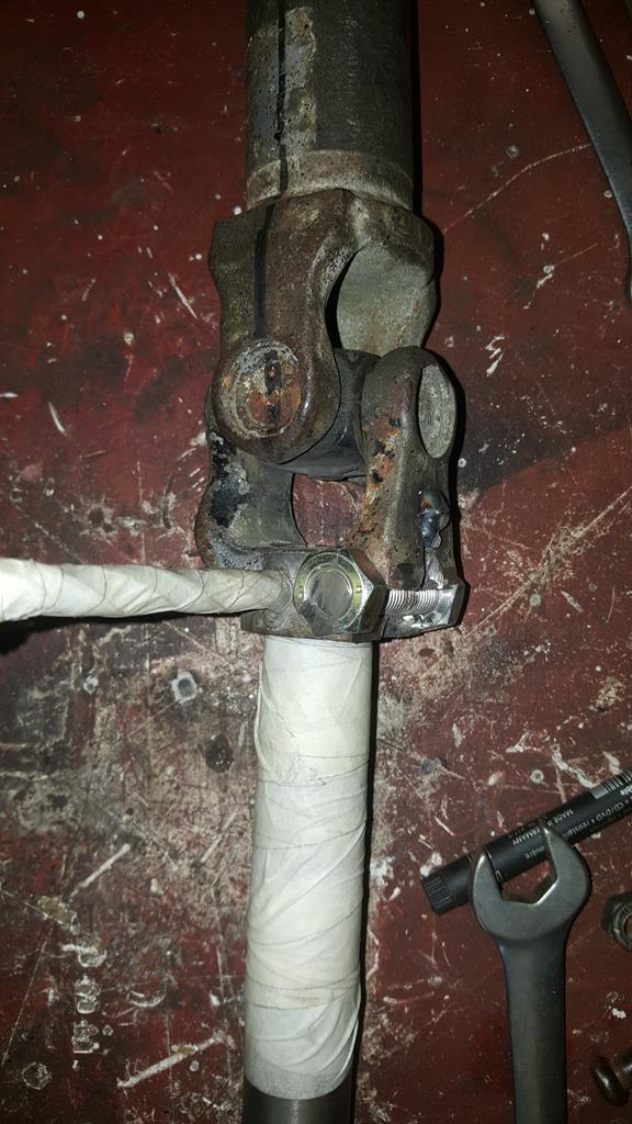 Part welded up.. A little at a time as I didn't want to fry the UJ. 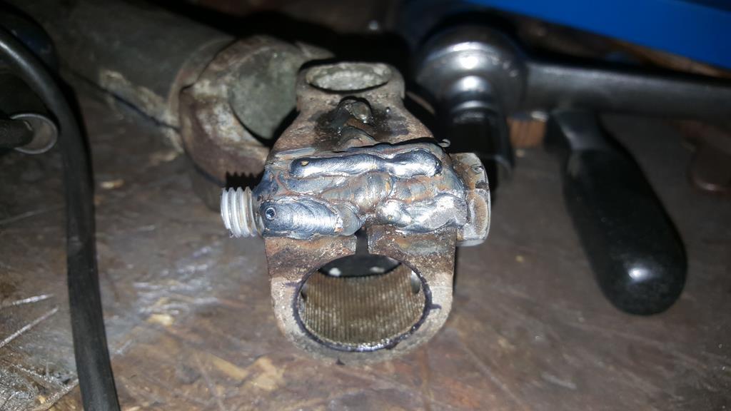 The bolt head and tread were cut off before more welding, then some shaping.. Still a little more to take off.. 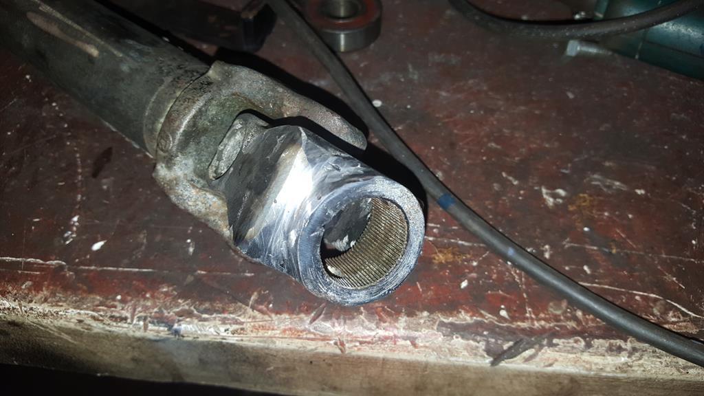 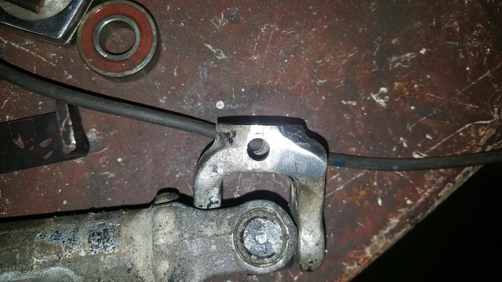 Oh, and I found a rather nice if rusty steel bar buried in the workshop, I guess I will be re-making the TB input shaft sleeve, but this time out of one piece.. It's a good job I have just got some more cutting tips and cooling fluid for the lathe 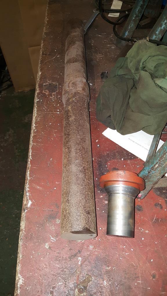 And to finish off... |
| |
My YouTube Channel www.youtube.com/user/UkWheelHorseBlokeQuote - D'you know, it's people like you, doing totally brilliant and pointless stuff like this that gives me a little hope for humanity |
|
|
|
|
Nov 25, 2017 20:19:33 GMT
|
A bit more of an update for you. With all the front drive train bolted back on the foot rest thingy needed a little trim to clear a UJ.. I will add a cover over the shafts/UJ's to add some leg protection should something go bang and start flapping about the place. 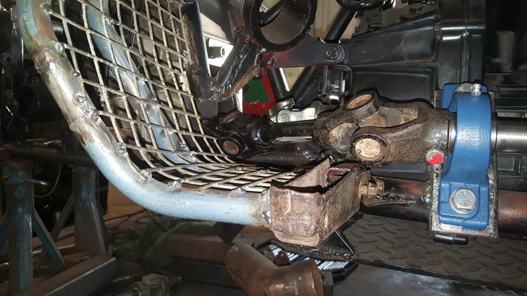 Before I started to cut any more metal out I put some strength back in with a nice bit of curved tube that clears the UJ When the frame is stripped back down I will add some extra metal to tie the tubes together neatly. 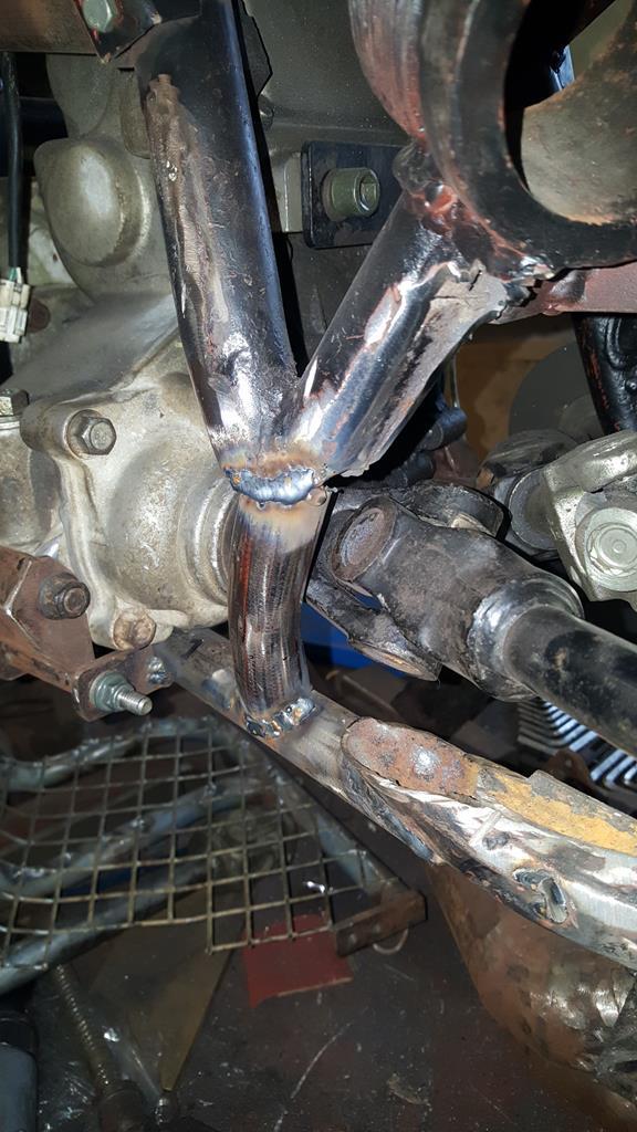 This join between old and new tubes just had to go! 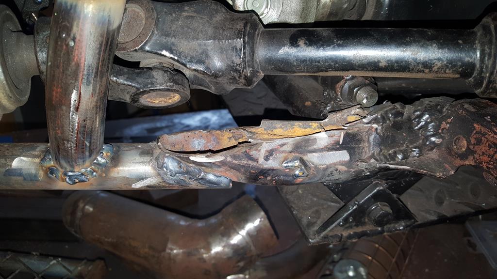 Hhmmm, nice rust inside one of the few remaining bits of the original FourTrax frame... It felt good to remove it 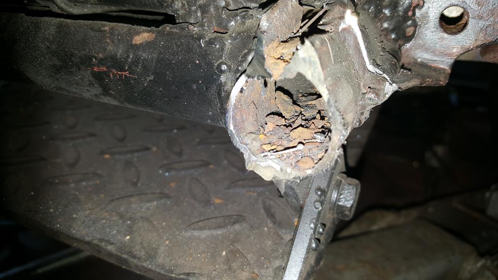 There is no neat way of joining big and little tube together, at least the other end is easy 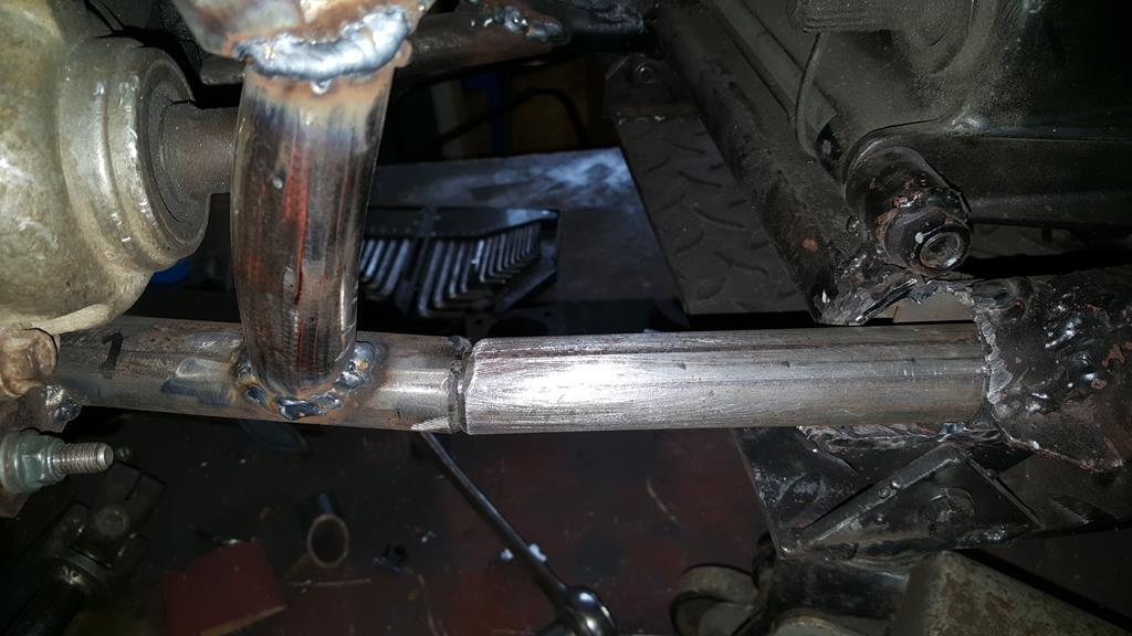 For extra strength a length of steel bar has been added inside, you can just about see it where the tubes join.. The steel bar does go all the way up and in the larger tube. 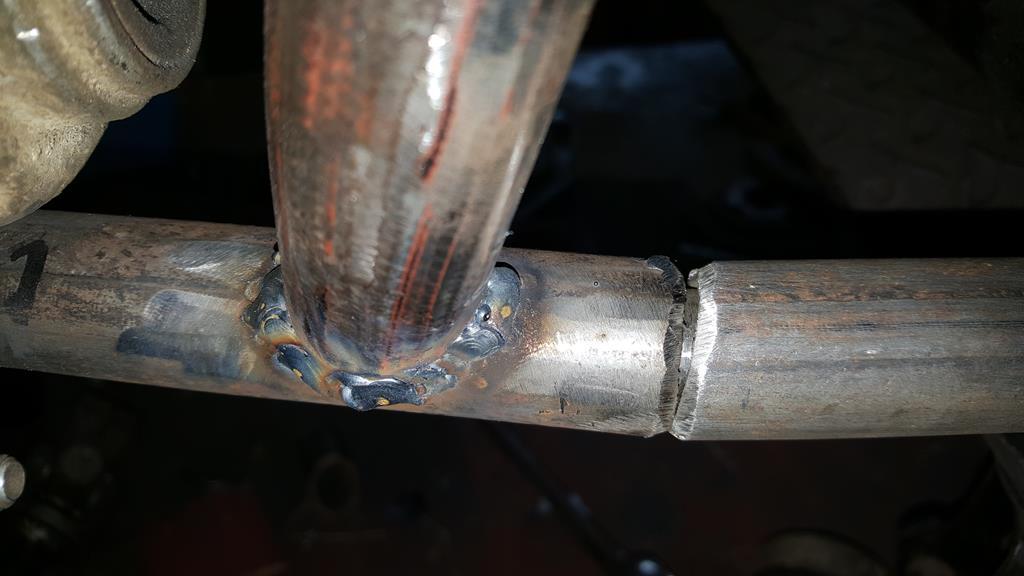 I like getting good value for money, think I might of got the maximum use out of this cutting disc 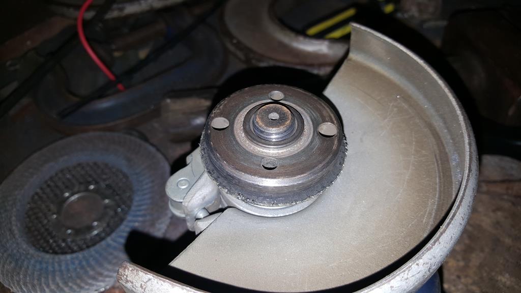 Compair it to a new disc!! While on the subject, some cheap cutting discs are better than others, I can't remember the make (Germany is mentioned on the Fleabay ad) but they are by far the fastest wearing most easily broken disc's I have ever bought! 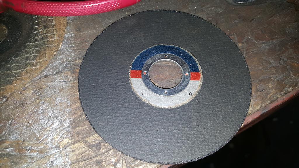 That looks better.. Way better than what was there. 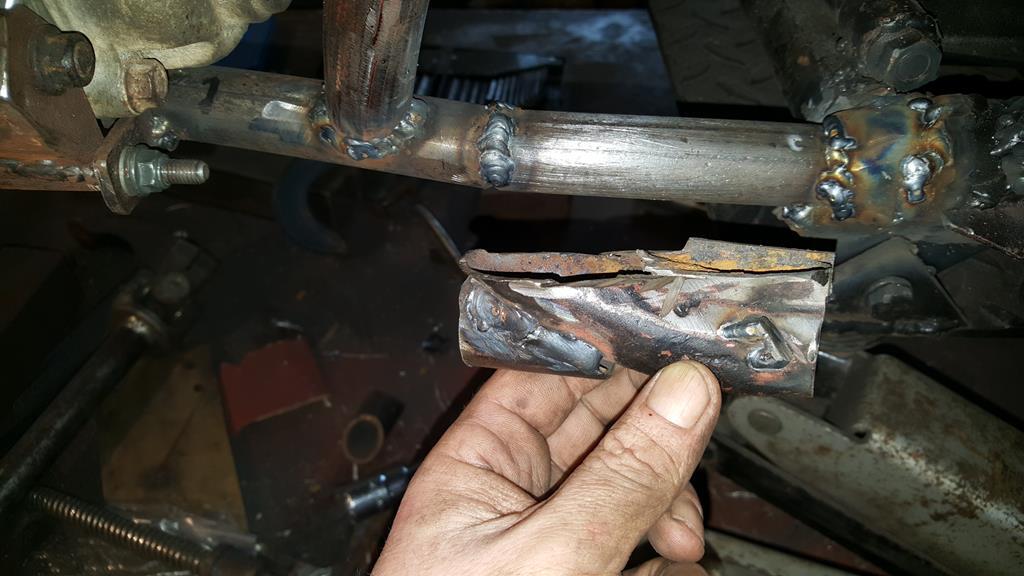 Now the fun part, getting drive from the Honda bike gearbox which points towards the back, out the left side of the frame. A thank you to Nigel at this point for getting a shaft, pulley and UJ off the remains of a Kubota flail mower before it went off for scrap... It really was that rotten! The UJ in question, heavy duty and with no play in the bearings at all. 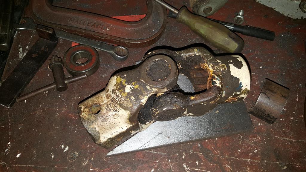 One side of the UJ is easy to attach as I have the shaft and roll pin that came out of it.. 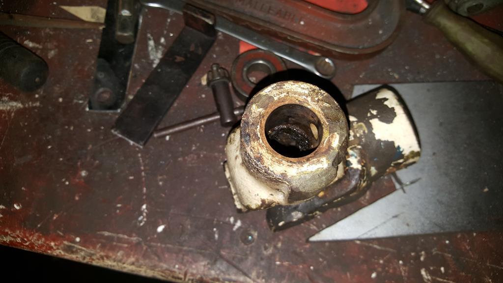 The other end has or (should I say had) some rather large splines! 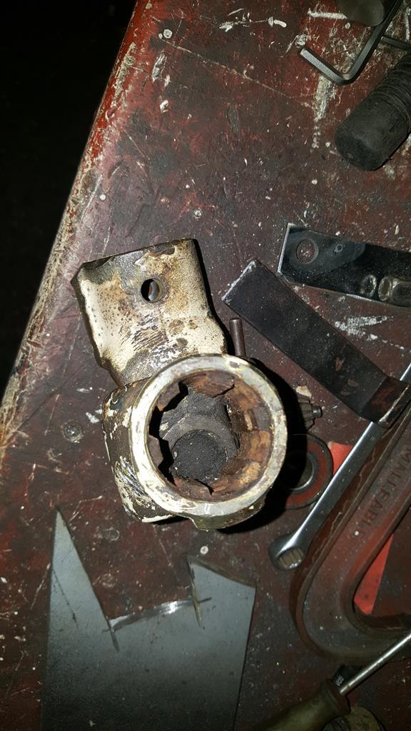 I'd be lost without a lathe, taking the OD down to size before cutting it off. 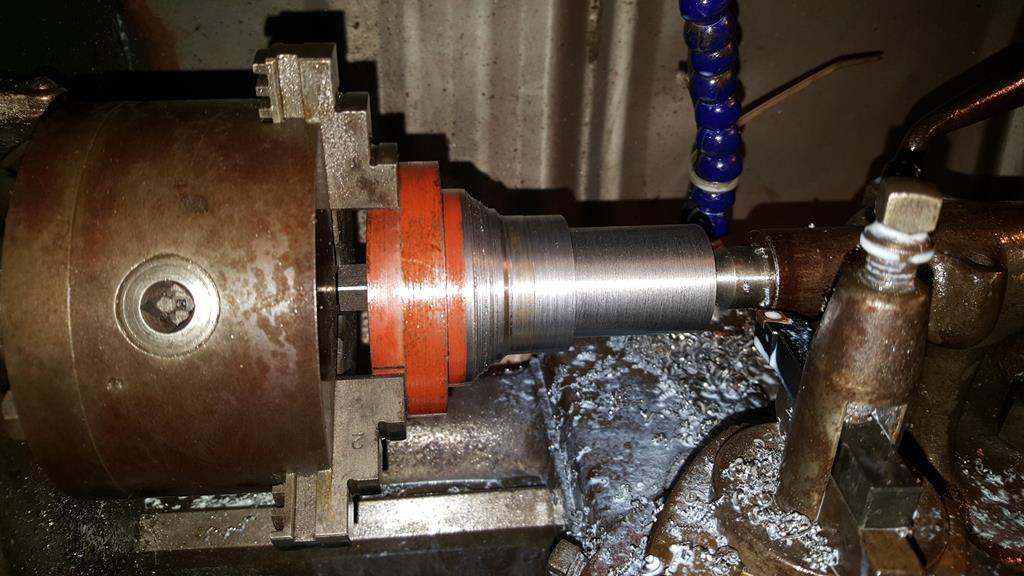 Boring the ID out, a couple of arty flying cooling fluid shots 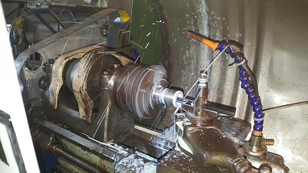 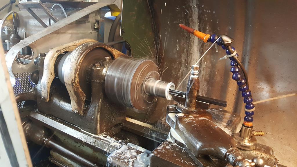 The finished sleeve, yes it was turned down from a lump of steel the same shape and size it's standing on! 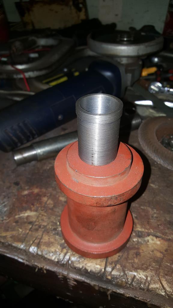 |
| |
My YouTube Channel www.youtube.com/user/UkWheelHorseBlokeQuote - D'you know, it's people like you, doing totally brilliant and pointless stuff like this that gives me a little hope for humanity |
|
|
|
|
Nov 25, 2017 20:42:12 GMT
|
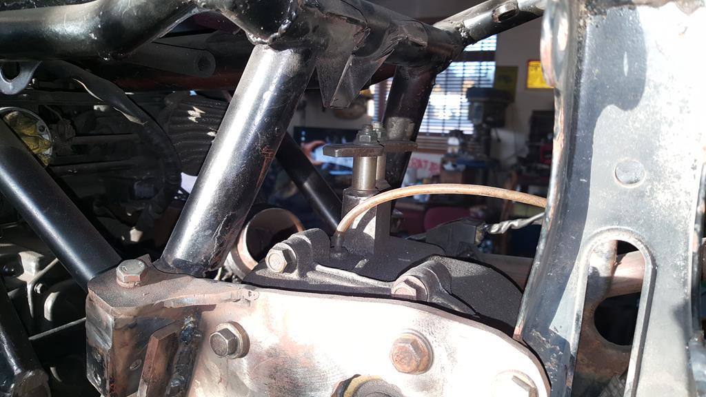
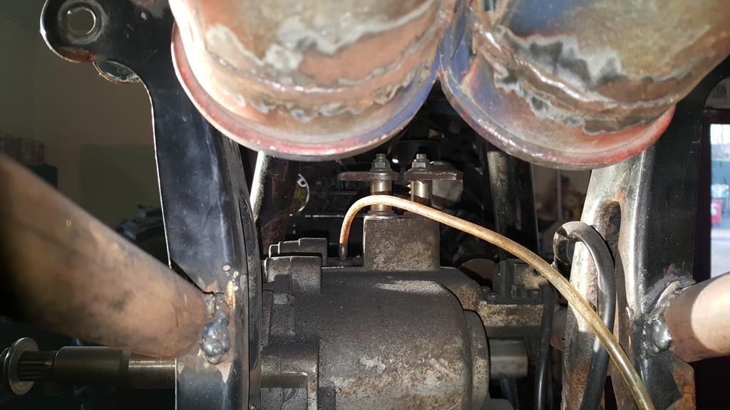
UJ, shaft and sleeve. 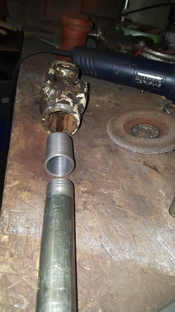 A nice tight fit.. The sleeve has now been welded into the end of the UJ, yet another roll pin will hold it all together. 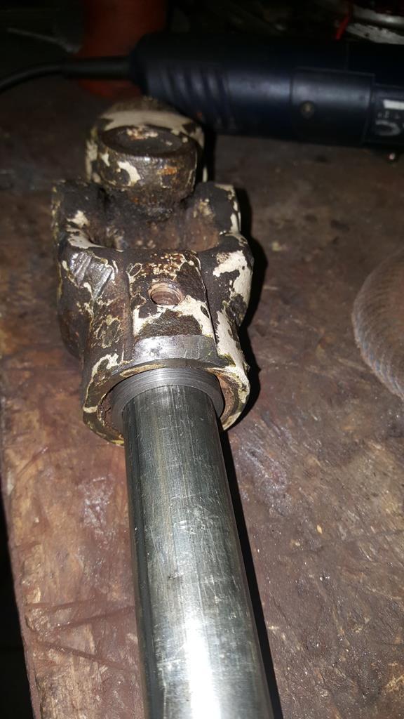 Starting at the back, or is it the front!... Er.. Back of engine we have a UJ with splines in one end to slide over the output shaft on the bike gearbox. 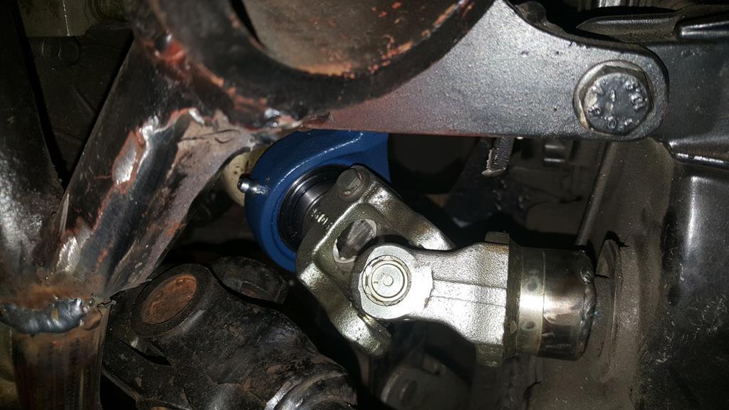 A shaft then goes through another bearing and into the Kubota UJ.. 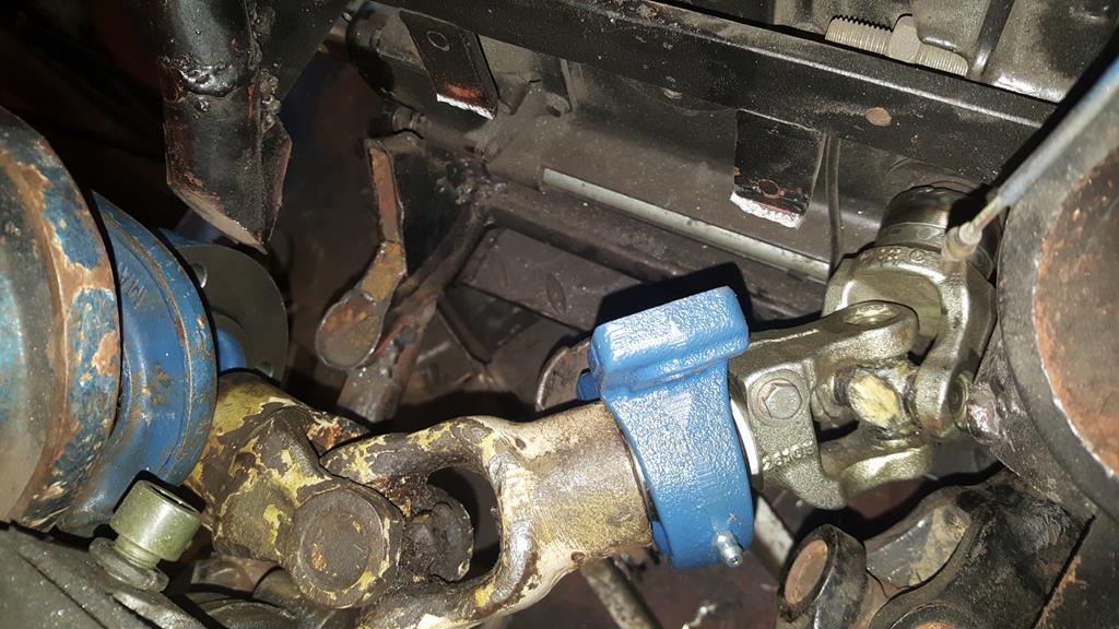 And comes out through the left side of the frame and another bearing. 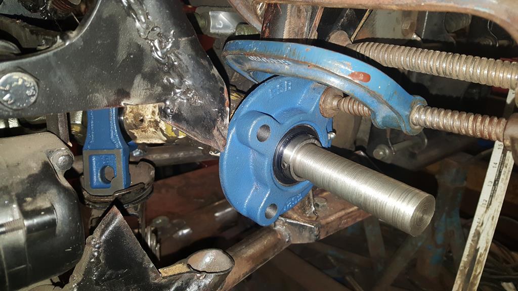 A chain and a couple of sprockets will give me drive into the transfer box 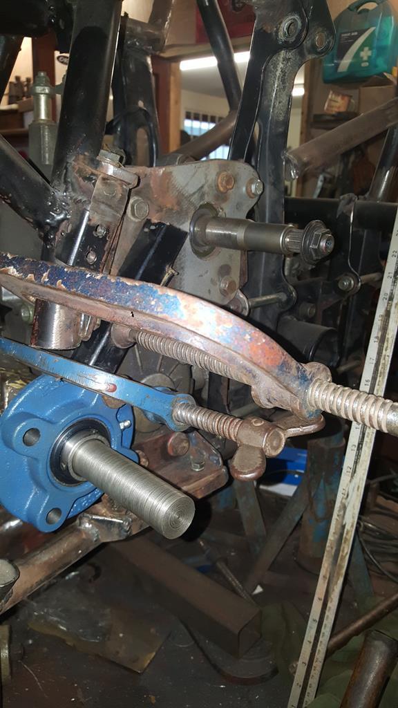 As you can see I have some metalwork to do to hold everything in the right place.. Space is tight but shafts and UJ's turn as the should without hitting anything or feeling "notchy" which proves the concept of it will all work The outer bearing needs something strong to bolt on to, so I dug out a bit of 8mm plate and set to on the lathe. 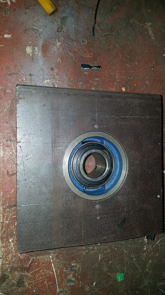 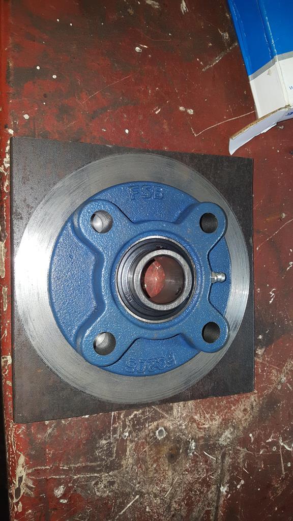 It will fit somewhere here, to make life more interesting the plate needs to be removable or I won't be able to get the transfer box back out the frame! 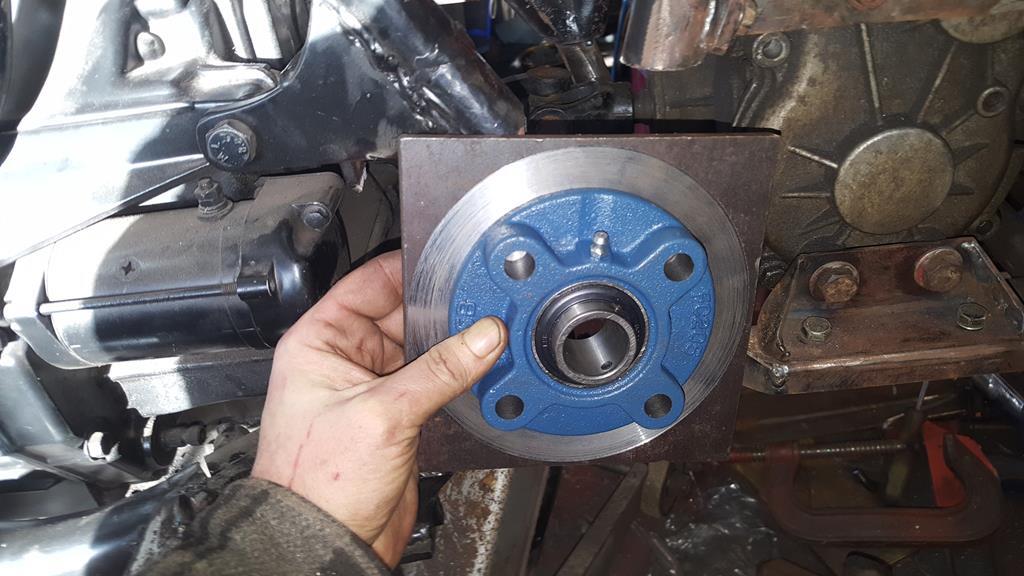 Before I started on the mountings I thought it would be wise to tidy up this bit of frame first. 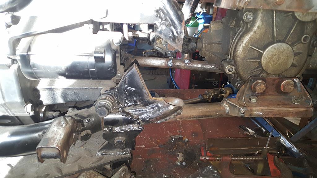 Mostly chopped out.. 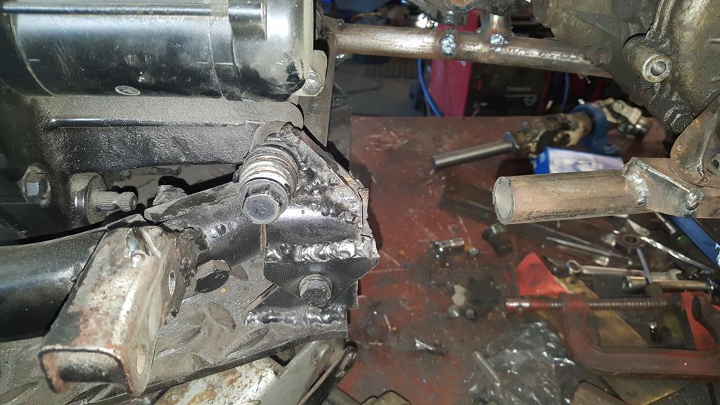 That looks better. 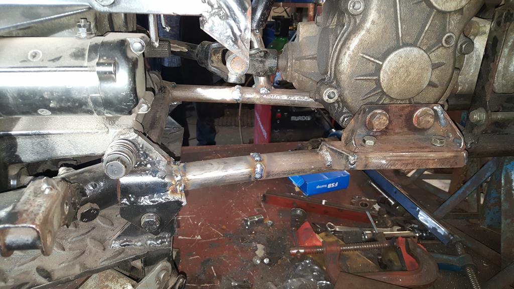 Plate and bearing set back in the frame a tad, it fit's rather well.. 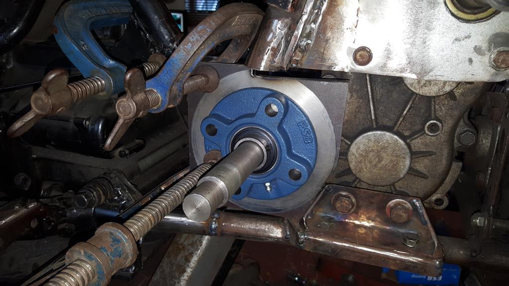 Plenty of UJ clearance by the transfer box. 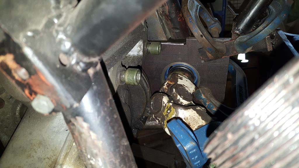 Before I can start mounting the plate I need to make sure both shafts are parallel to each other.. I have started making a jig thingy to do just that job.. But your going to have to wait to see it as I've not finished making it yet.. And that is this build thread up to date again.. 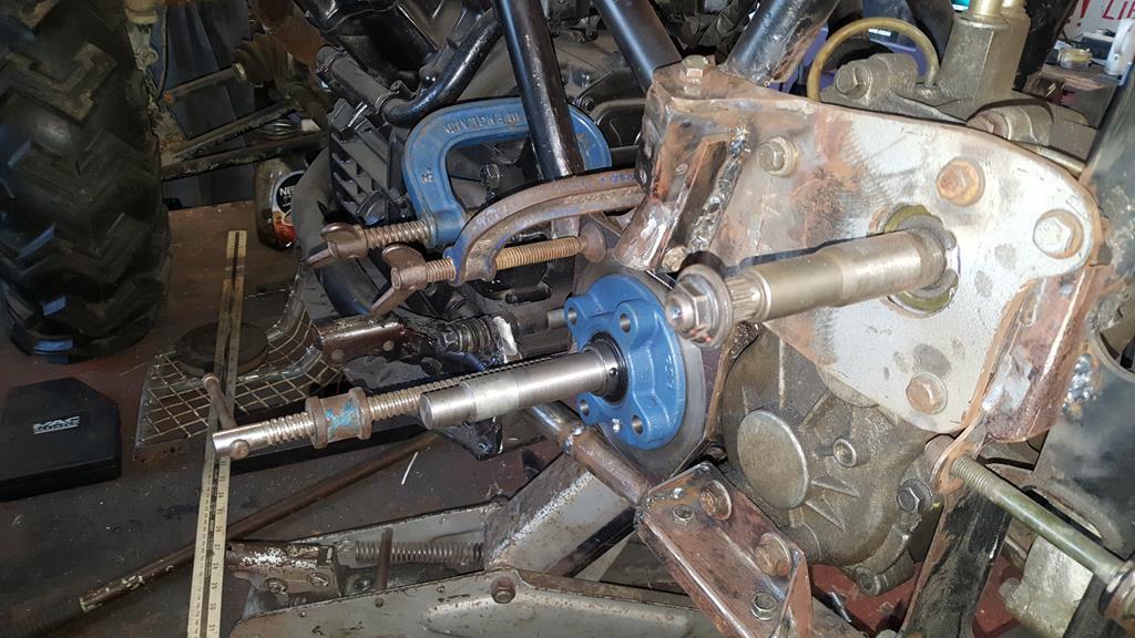 |
| |
My YouTube Channel www.youtube.com/user/UkWheelHorseBlokeQuote - D'you know, it's people like you, doing totally brilliant and pointless stuff like this that gives me a little hope for humanity |
|
|
|
|
|
|
Don't think I've ever, ever seen so many UJ's in such close proximity before. Proper packaging! |
| |
|
|
|
|
|
|
|
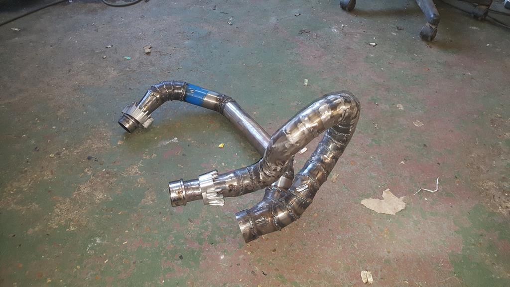
Don't think I've ever, ever seen so many UJ's in such close proximity before. Proper packaging! Thanks George, enjoy the sight of tight UJ packaging as it won't be there by the end of this update Here's the jig thingy I make to keep the shafts parallel. It doesn't lok that much but both the tubes are a nice snuff fit on the shafts they have to fit on. A lot of time was spent making sure both tubes are parallel to each other.. Trim, measure, trim, measure, trim, measure.. Weld measure, weld a bit more, measure.. You get the picture. 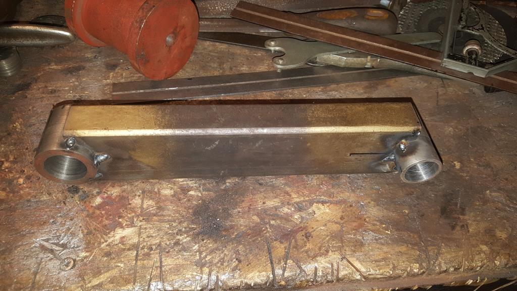 Fitted.. The shafts are now parallel to each so I can start working out how to mount the bearing plate. 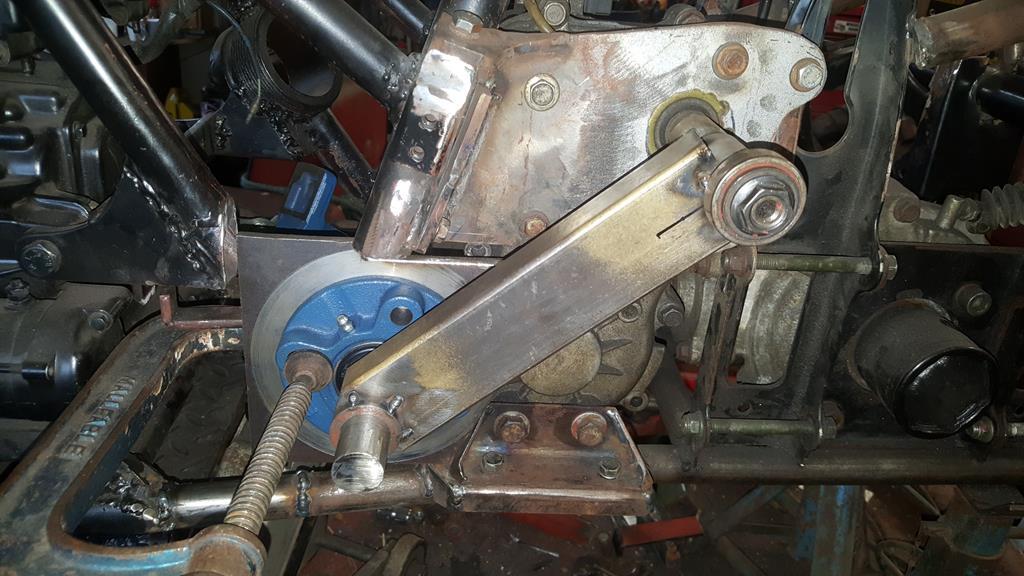 Out of interest I put the foot rest/guard thingy on to check it still fitted... Not bad, I will only have to loose a small amount of foot space to fit a sprocket with guard of course. 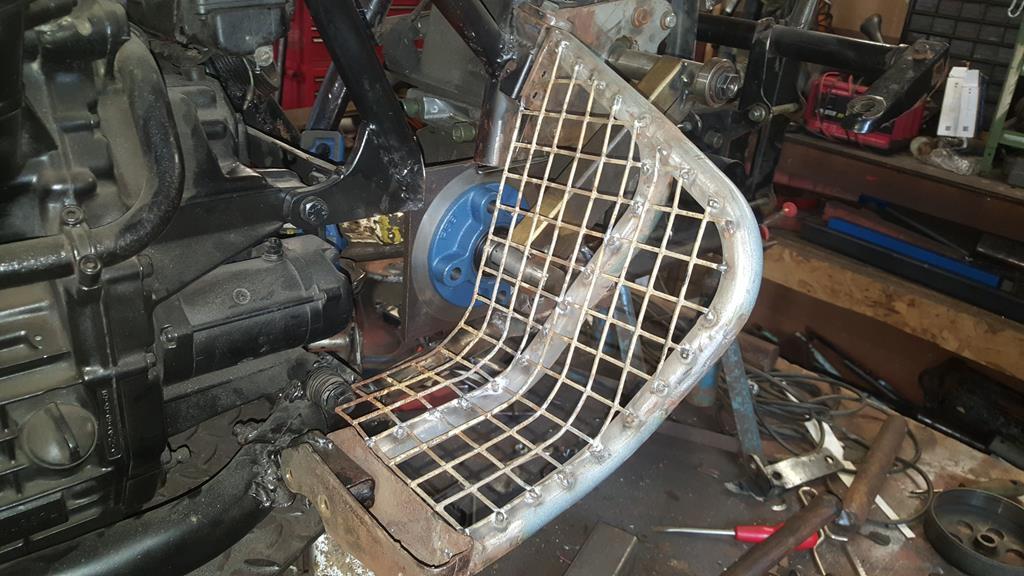 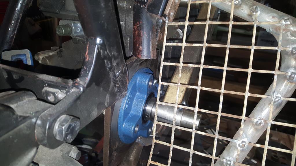 It was roughly at this point that a couple of comments left on Farcebook had me thinking about how safe the right turn UJ set-up actually would be.. Tight UJ angles and high spinning speeds are not the best mix! Sooooooo..... I started on the exhaust instead There was no way the exhaust system I had built would fit back on with a transfer box and a dive shaft in the way, the only part that fits is the big bore pipe that runs down the side of the engine through the frame! So a bit of a re-make is needed, I started at the front after slicing off the bits that fit into the engine.. The only tube I have enoug of is a bit bigger than I had been using, so how to go from something small to the bigger blue bit size! 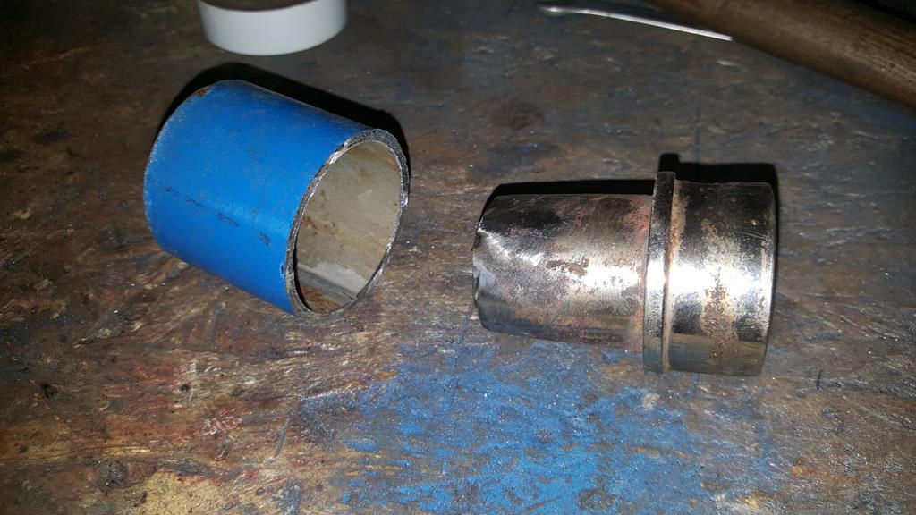 Find a bit of tube that's slightly bigger than the small bit but slightly smaller than the big blue bit and make four long-ish cuts in it. 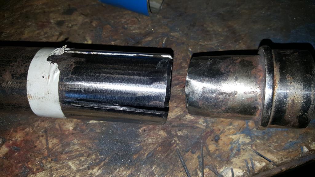 A hose clip squeezes it down to size. 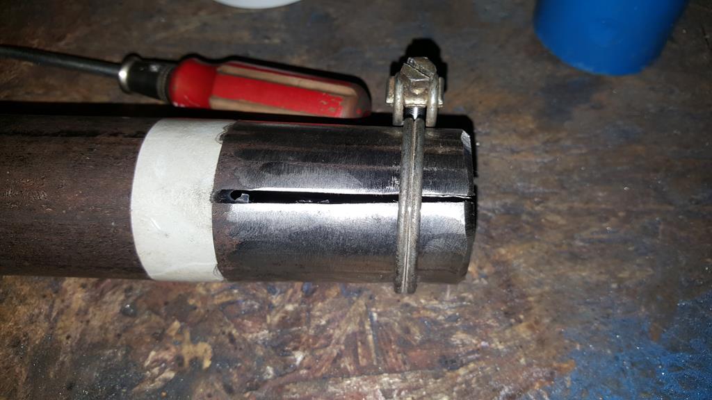 Welded on and extra tube trimmed off. 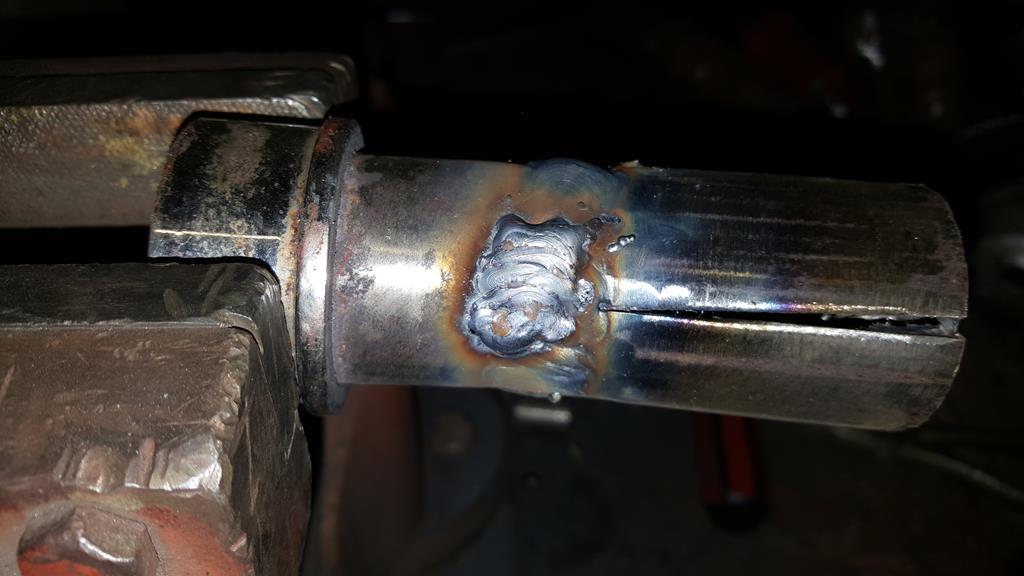 Welds cleaned back. 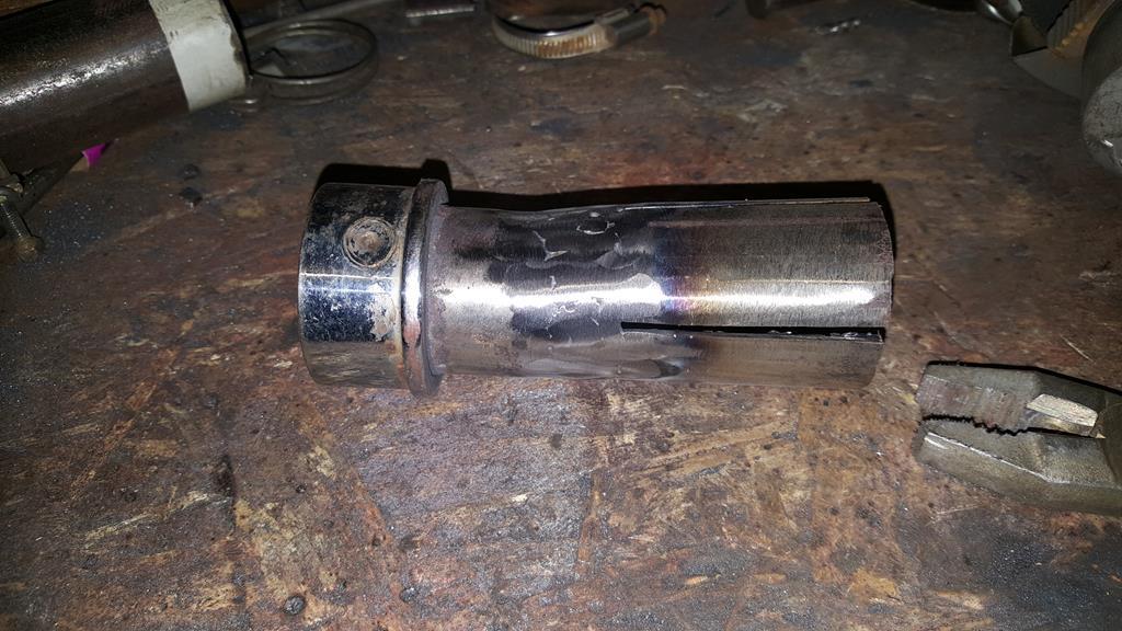 A bit of hammer work soon had the other end a bit wider.  Welded on to the big bore pipe. 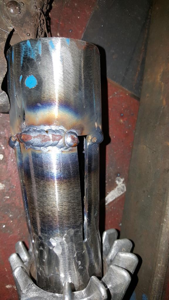 Lot's of careful welding later had the gaps filled up. 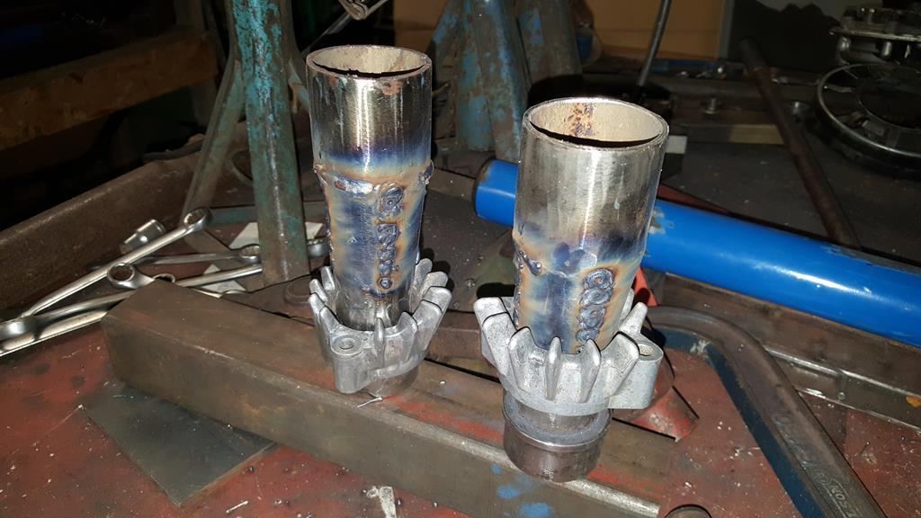 Test fitted to the engine, one side cleaned up. Now I have these made I can work out how the next part of the system.... But that's something for Monday.. 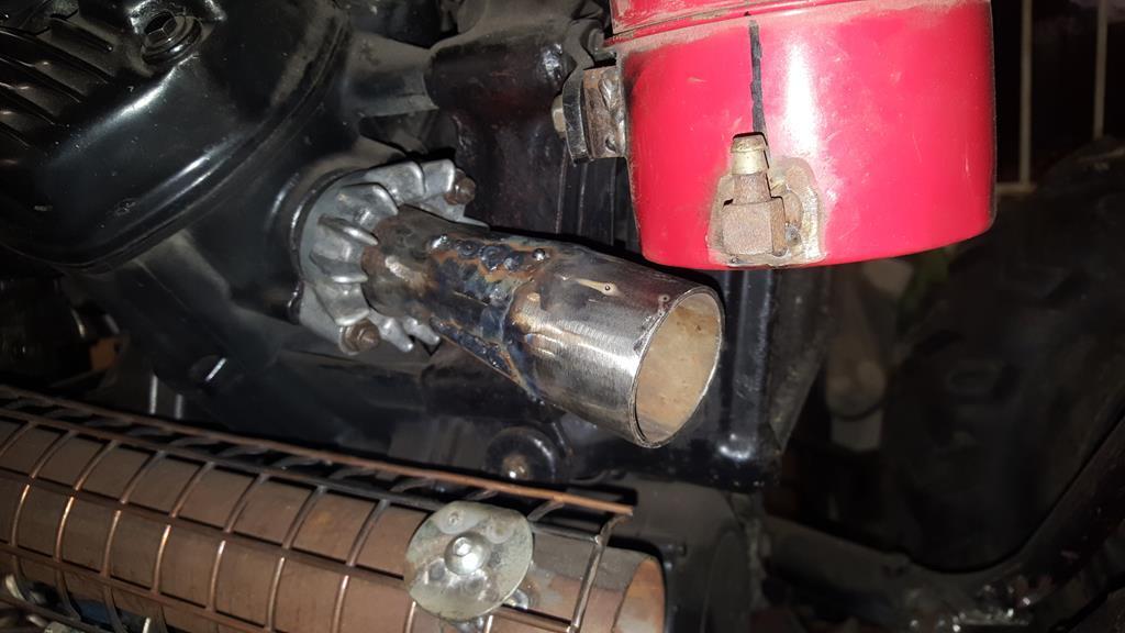 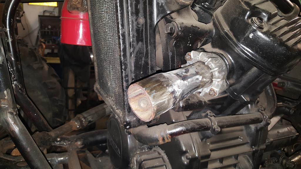 Oh... the slight change of plan... With the UJ's etc removed I found there is just enough space to fit this er... final drive? 90'd drive thingy from the very same Honda Silverwing that gave it's engine up for Why Not all those years ago! 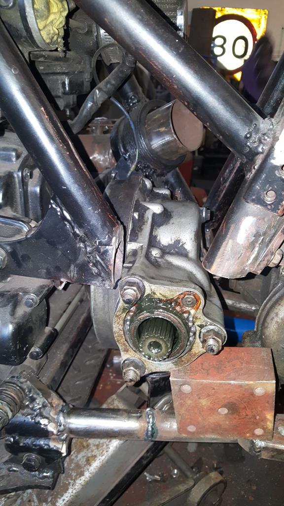 I will need to fit a chain n sprocket to get the power from the bike gearbox into the 90'd drive thingy which has a 5 to 1 ratio (I can "gear" that ratio out), and yes it will spin the right way 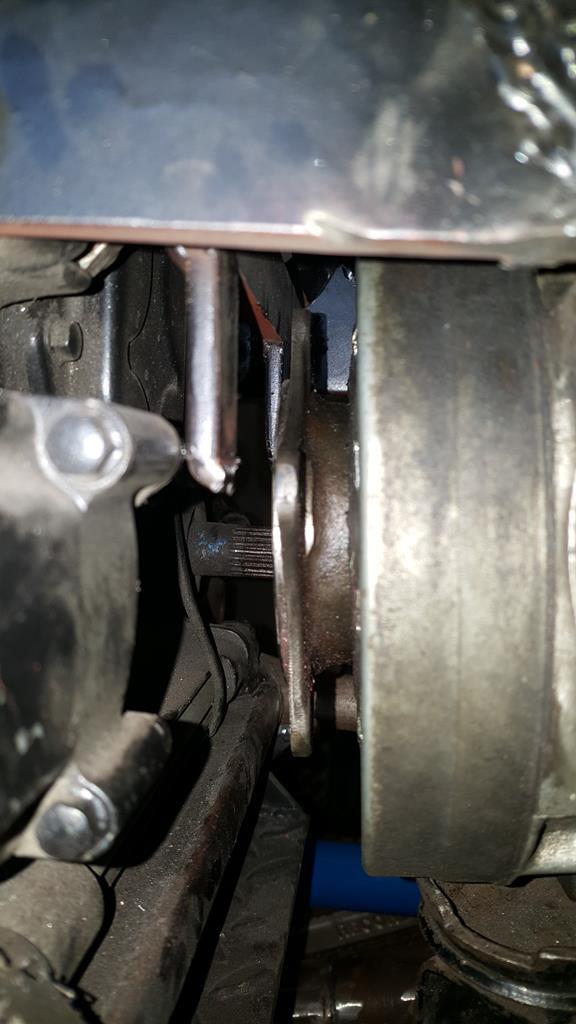 And to finish off a couple of photos of the unit I had taken to put it on Fleabay.. Quite glad I didn't get around to listing it 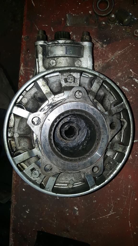 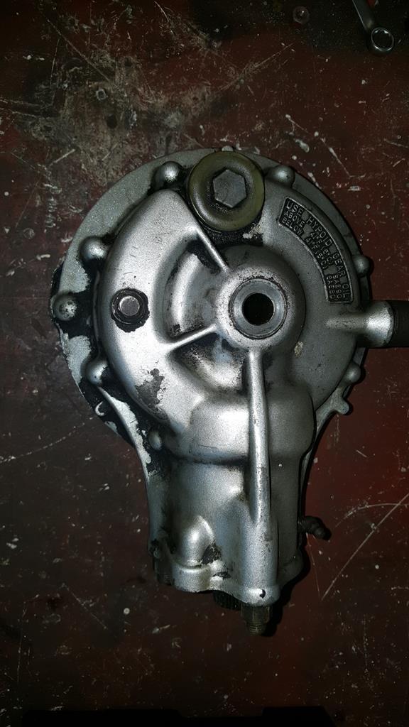 Oh, here's the latest video.. Enjoy.. |
| |
My YouTube Channel www.youtube.com/user/UkWheelHorseBlokeQuote - D'you know, it's people like you, doing totally brilliant and pointless stuff like this that gives me a little hope for humanity |
|
|
|
|
Dec 13, 2017 15:44:27 GMT
|
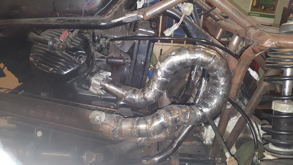
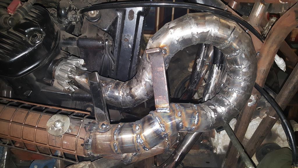
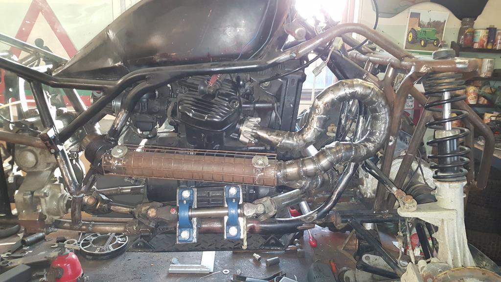
Owdo all, time for an exhausting update :lol: Having short stubby pipes sticking out the engine I needed to make them a bit longer and join together. The first bend, I'm going for a more agricultrual look with the exhaust system to make it stand out a bit from the swoops of the frame, so lots of pie cuts going on. 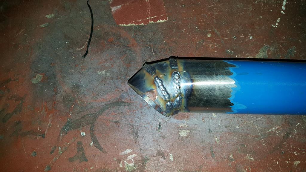 Plenty of penetration which is good to see 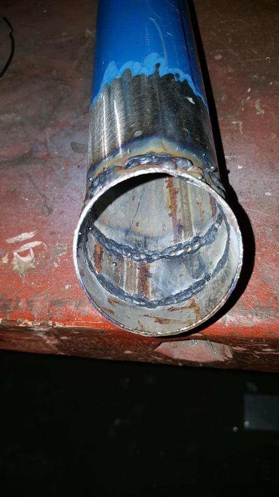 The N/S pipe almost done. The long bit that goes across the frame was welded in place first the couple of bits of box were there just to keep it in the right place, below the radiator.. The rest was made up to fill the gap. 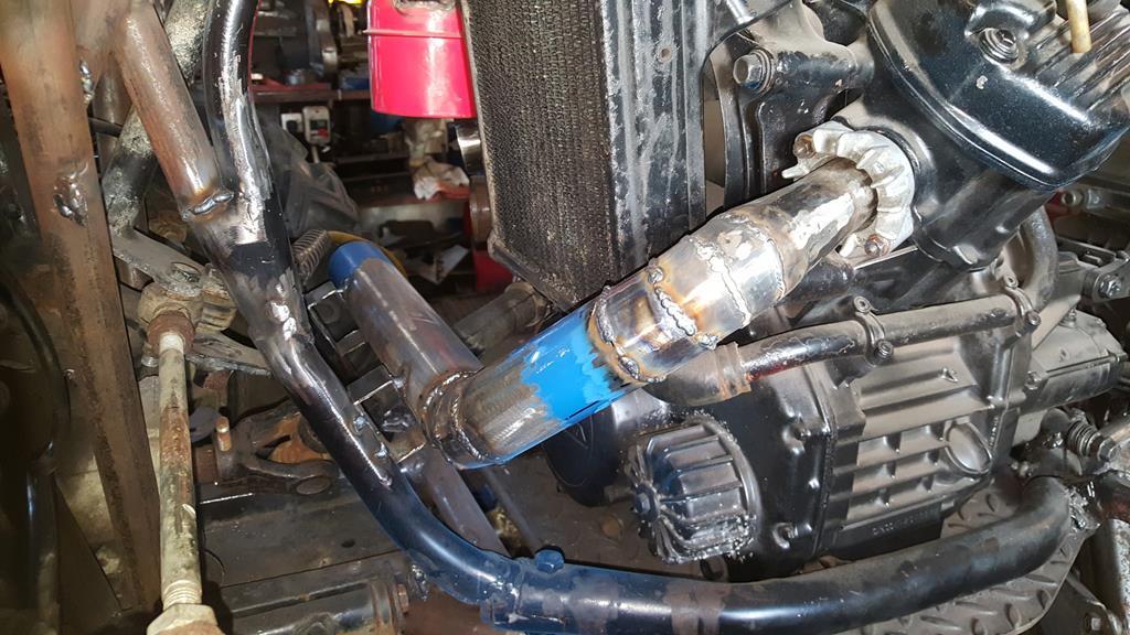 Before doing the O/S pipe I needed to know how it was all going to fit into the main pipe which runs along the side of the engine.. 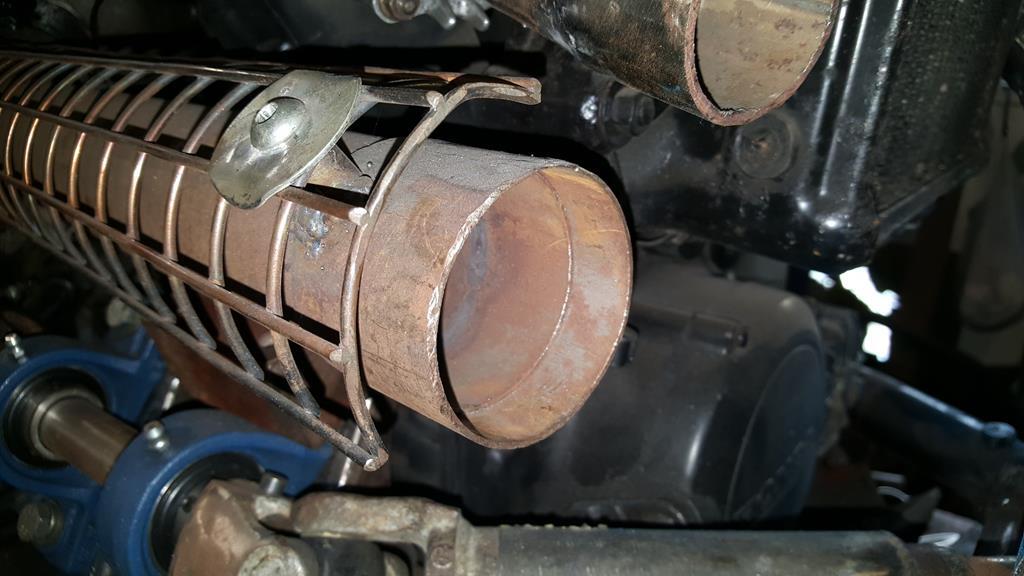 Sooooo, how to fit two of the smaller pipe into the bigger one!! 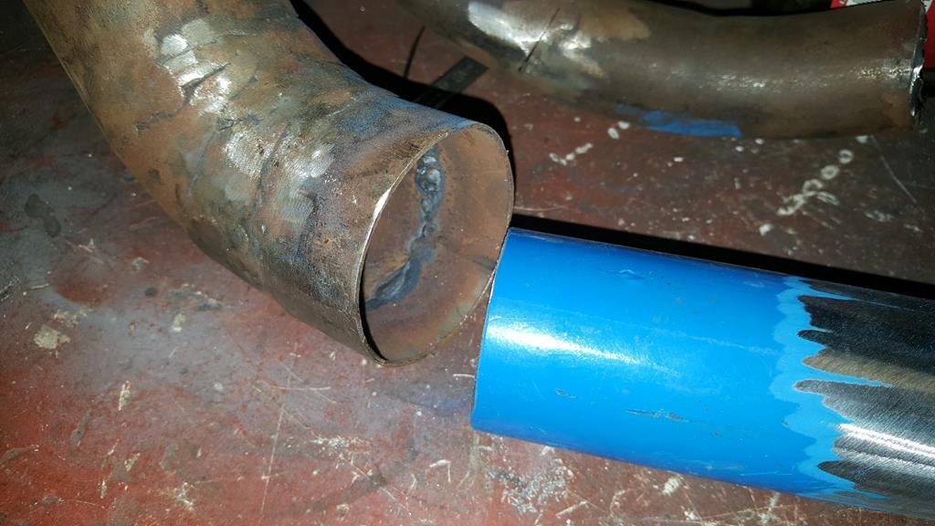 Some measuring and cutting later.. The pipes are over length as I knew I'd need to trim them just not quite sure where yet. 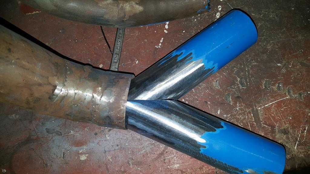 Welded up and slotted in place. 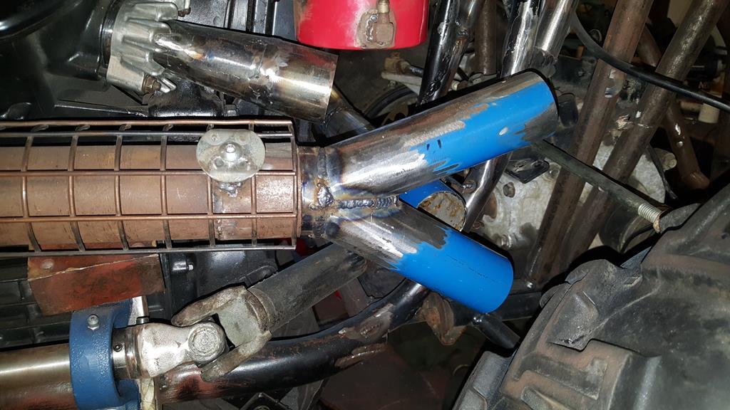 And joined to the N/S pipe. 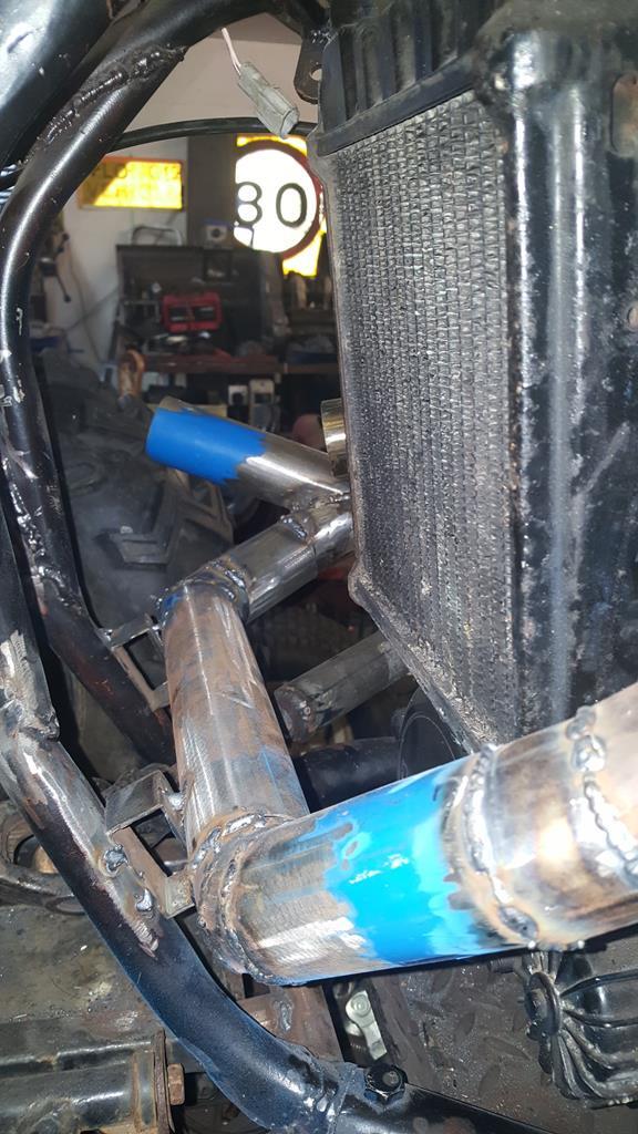 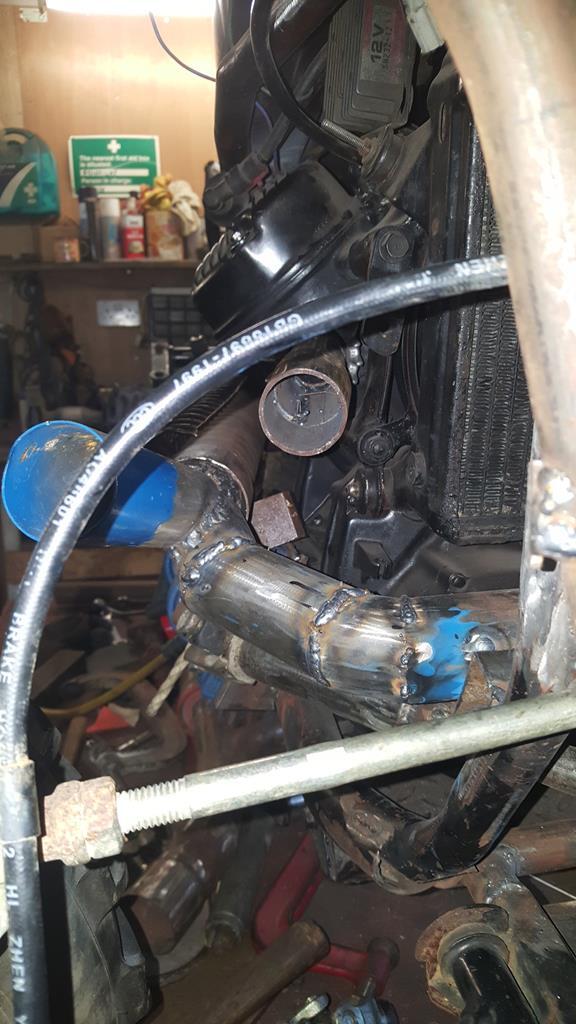 Before you ask.. Yes the welding rubbish was cleaned from the inside of the pipe sticking out the engine before anything else was welded to it.. |
| |
My YouTube Channel www.youtube.com/user/UkWheelHorseBlokeQuote - D'you know, it's people like you, doing totally brilliant and pointless stuff like this that gives me a little hope for humanity |
|
|
|
|
Dec 13, 2017 15:50:04 GMT
|
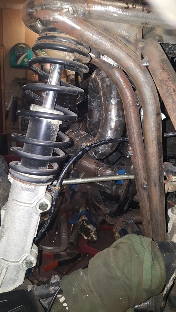
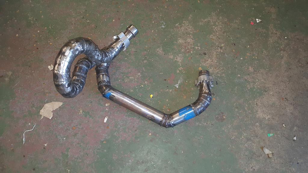
These CX/GL 500 Honda engines only run at their best if both cylinder/header pipes are the same length each side... The N/S pipe came in at 30 1/2 inches, so I had to try and fit that length into a rather small space on the O/S and still have good gas flow!! A long bit of pipe with lots of pie cuts marked out.. 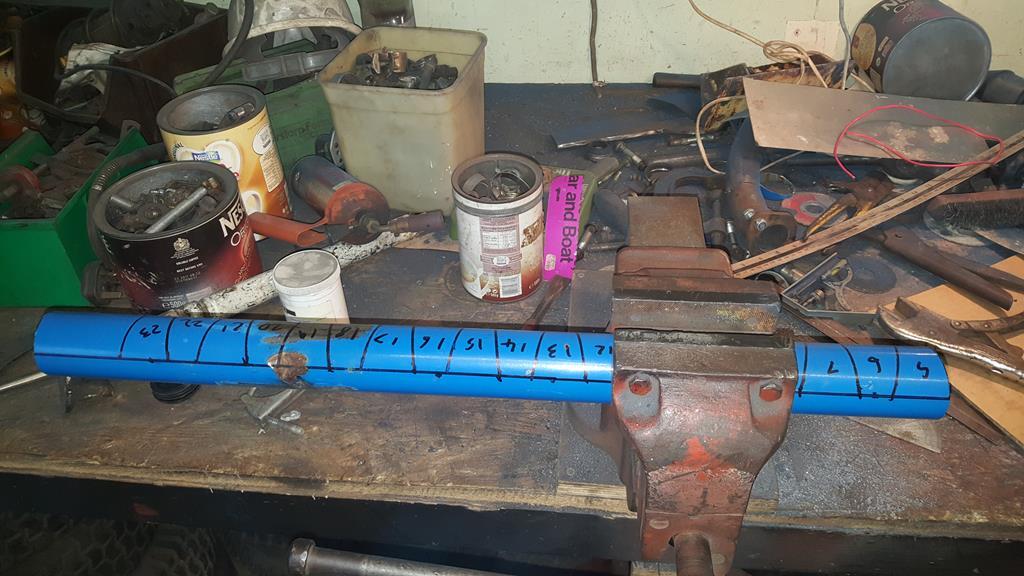 Can you see where I'm going with this? 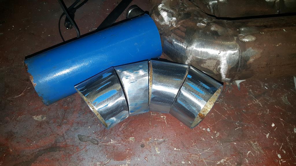 A shorter bit of pipe. 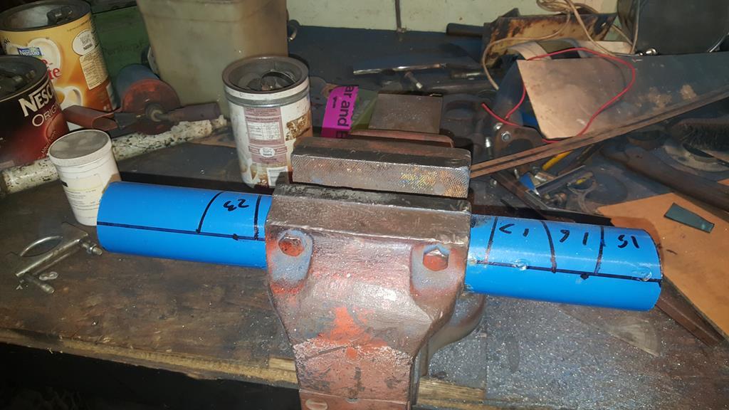 Lot's of hollow metal pies.. 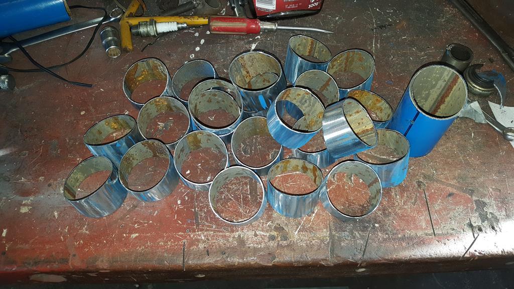 And lots of blue power coating on my bench from cleaning the pies. 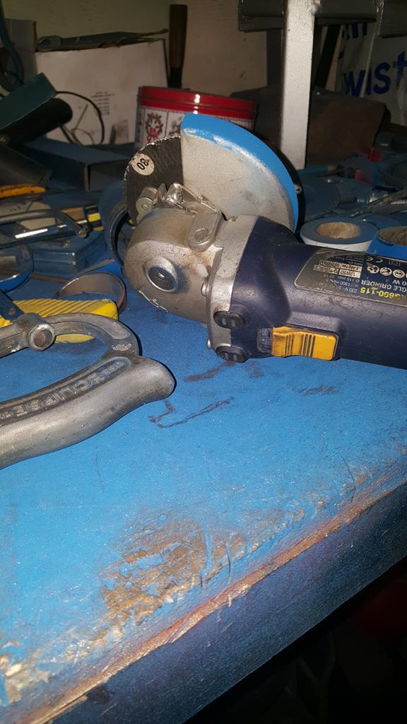 This bit of cardboard was used to work out some angles to cut, the metal version will fit about here. 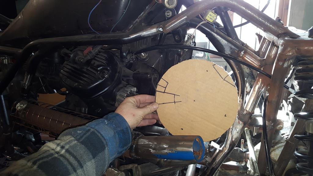 So I didn't end up welding up a bit hollow Polo mint I added a bit more cardboard to the mix. 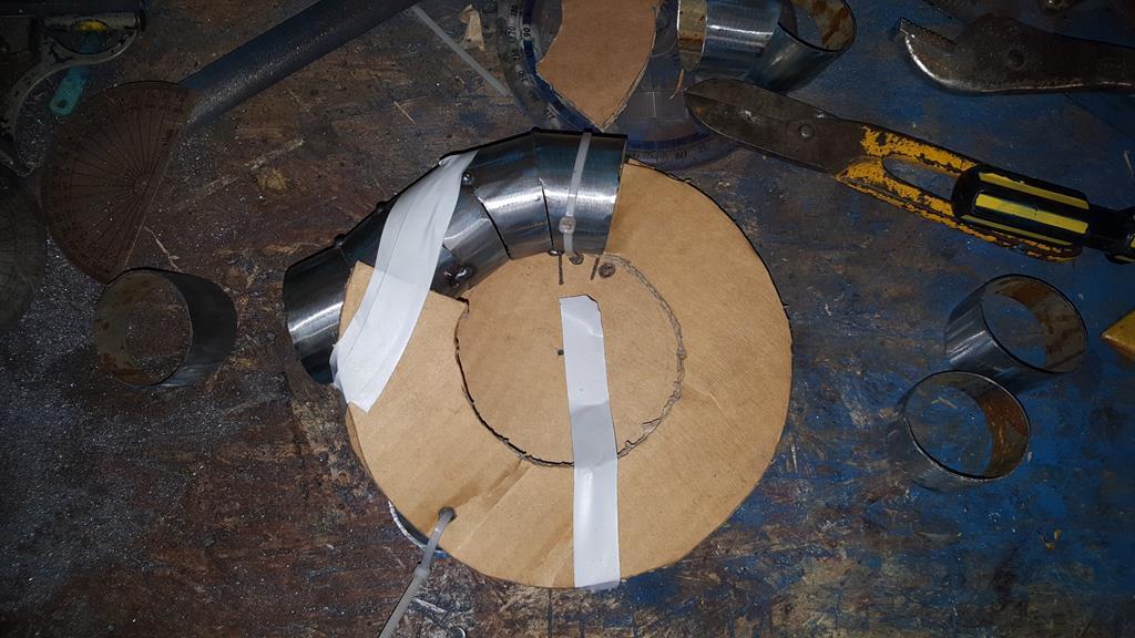 As long as the loop follows the spiral it should not end up hitting it's self 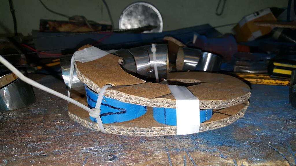 |
| |
My YouTube Channel www.youtube.com/user/UkWheelHorseBlokeQuote - D'you know, it's people like you, doing totally brilliant and pointless stuff like this that gives me a little hope for humanity |
|
|
|
|
Dec 13, 2017 15:55:54 GMT
|
|
|
| |
My YouTube Channel www.youtube.com/user/UkWheelHorseBlokeQuote - D'you know, it's people like you, doing totally brilliant and pointless stuff like this that gives me a little hope for humanity |
|
|
|
|
|
|
Dec 13, 2017 21:47:11 GMT
|
|
This is insane. You have some awesome skills mate. You must be a genius to come up with your ideas.......or bonkers...maybe both a bit.
Loving this thing anyway
|
| |
|
|
|
|
|
Dec 13, 2017 22:09:57 GMT
|
As someone has put a transfer box right in the way Don't you just hate it when they do that? As ever, top work! |
| |
|
|
|
|
|
Jan 17, 2018 20:58:49 GMT
|
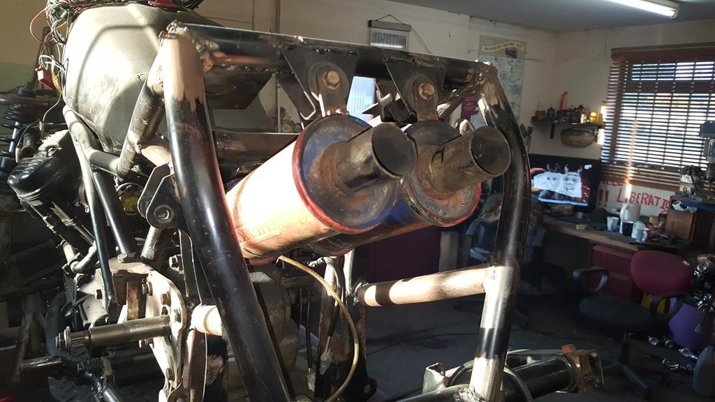
This is insane. You have some awesome skills mate. You must be a genius to come up with your ideas.......or bonkers...maybe both a bit. Loving this thing anyway Thanks rblote, I'm not sure on the genius bit, but bonkers I will put my hand up to As someone has put a transfer box right in the way Don't you just hate it when they do that? As ever, top work! Thanks George, what I can't work out is why it's always me that puts something in the way on my builds.. It would be nice to blame someone else for a change Hi all, I'm back after taking a break from the internet for a while, sometimes it has to be done to try and keep some sanity Back to the exhaust system.. In order to find a bit more space around the transfer box I moved the end cans back by about 3 inches.. 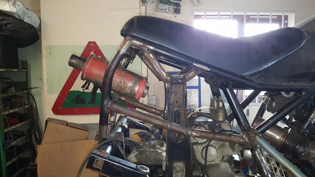 This was one of the end can mounting brackets.. 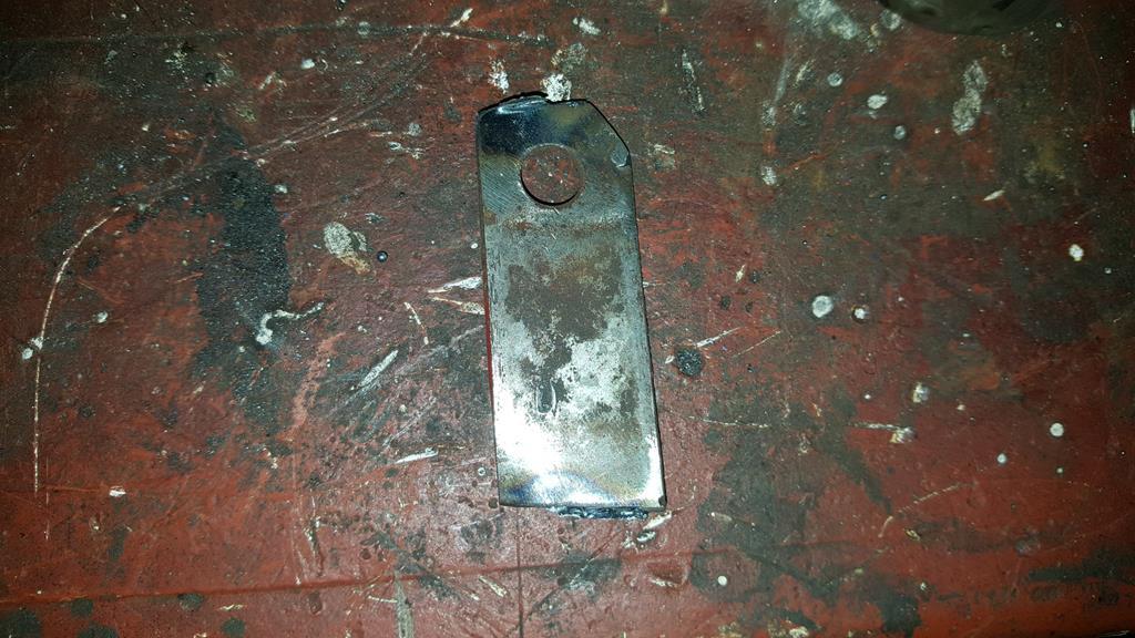 These are the upgraded versions, stronger and look much better. 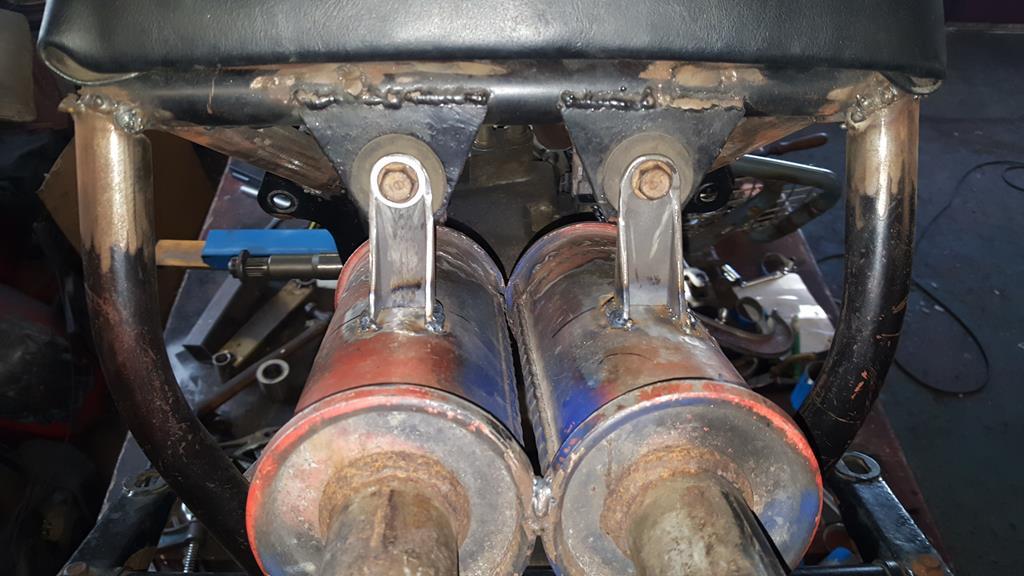 Some more slicing and dicing of tubes saw both end cans plumbed together.. 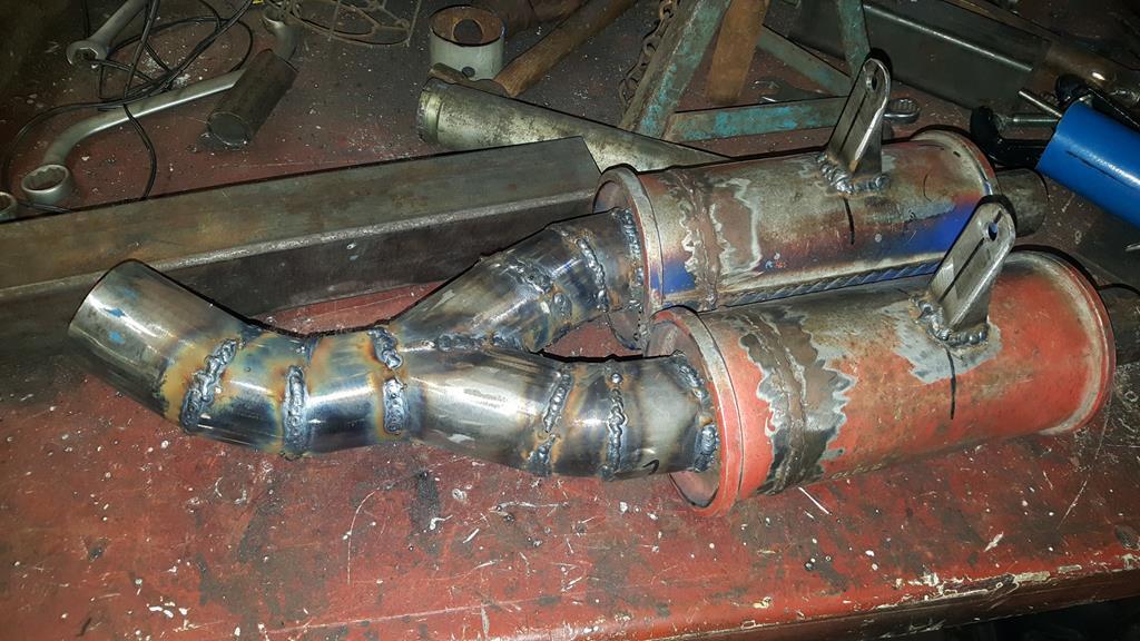 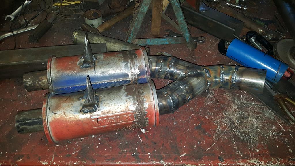 The solution to joining the front and back pipes together was this ear trumpet shaped bit of pipe. 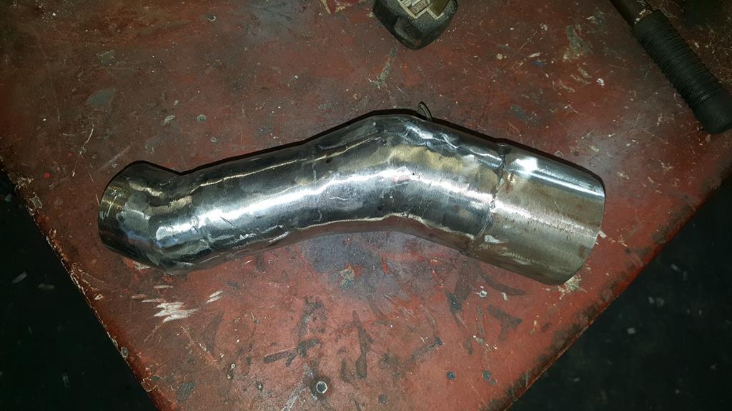 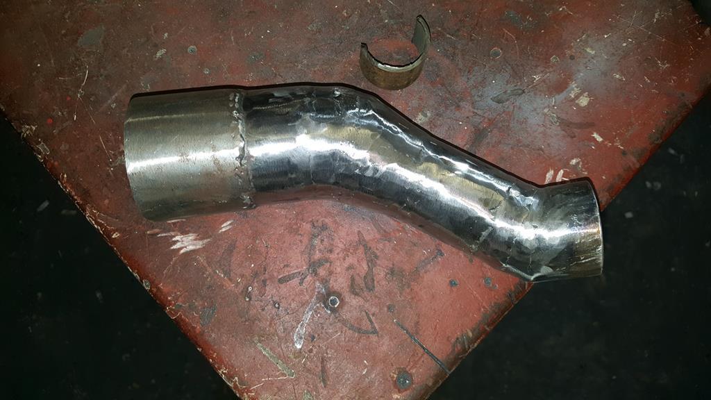 It's a tight fit around the transfer box, a very thick ally heat shield will be going between the exhaust and the black electrical gizmo with the word up, upside down.. Don't want to melt it! Thinking on it, if it's only an idiot light switch it wouldn't be hard to rig up another switch on the shifter linkage and do away with the one that's a bit too close to the exhaust.. 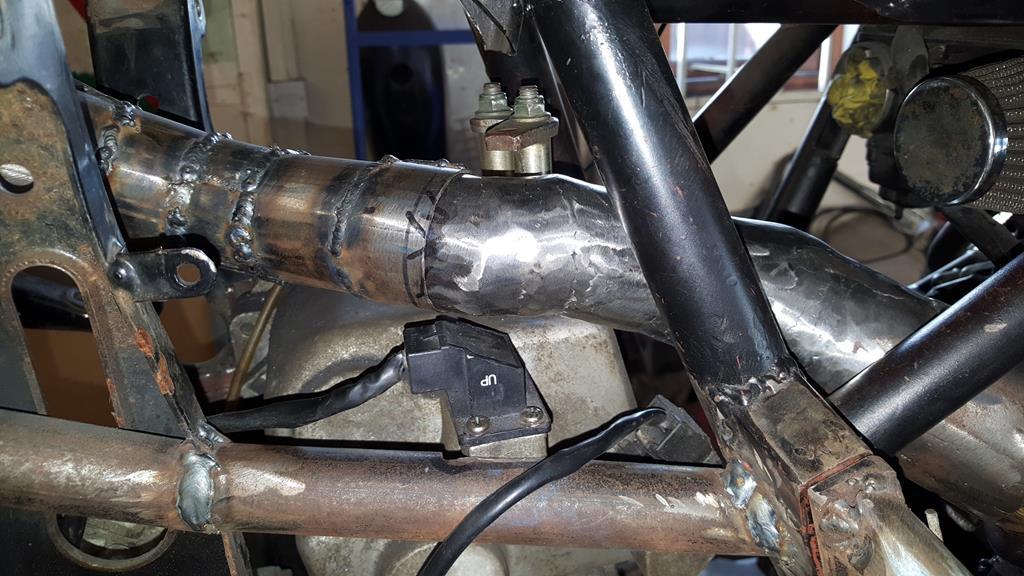 Apart from grinding down lot's of welds that's the exhaust system done 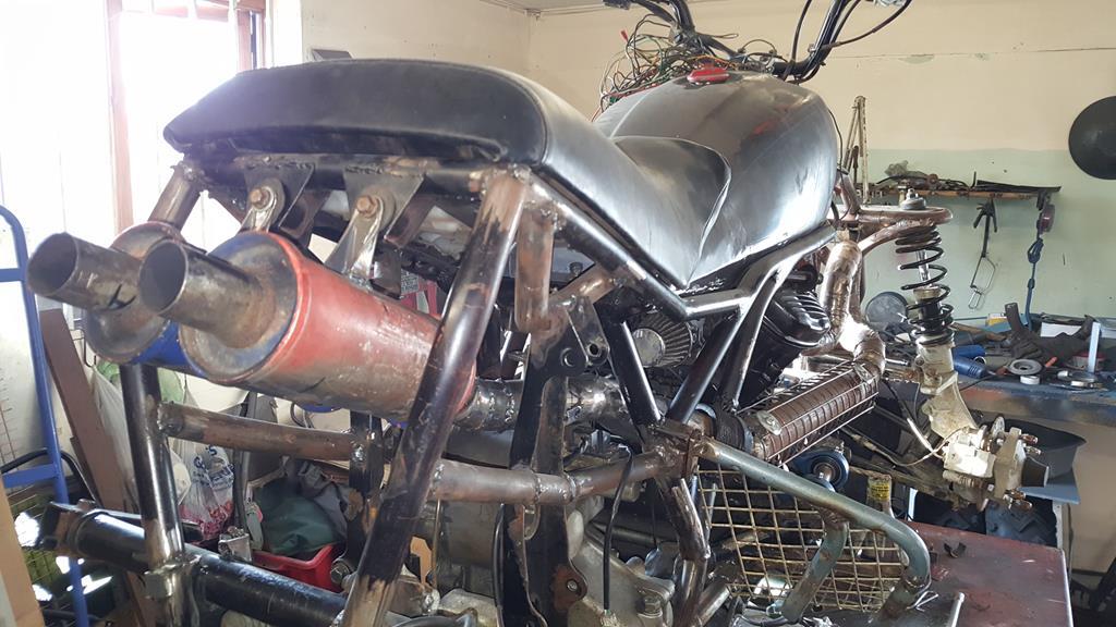 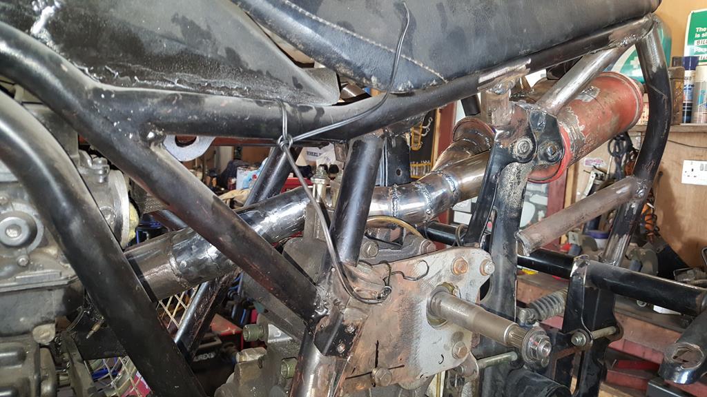 Next on the hit list to sort is the shifter for the transfer box.. 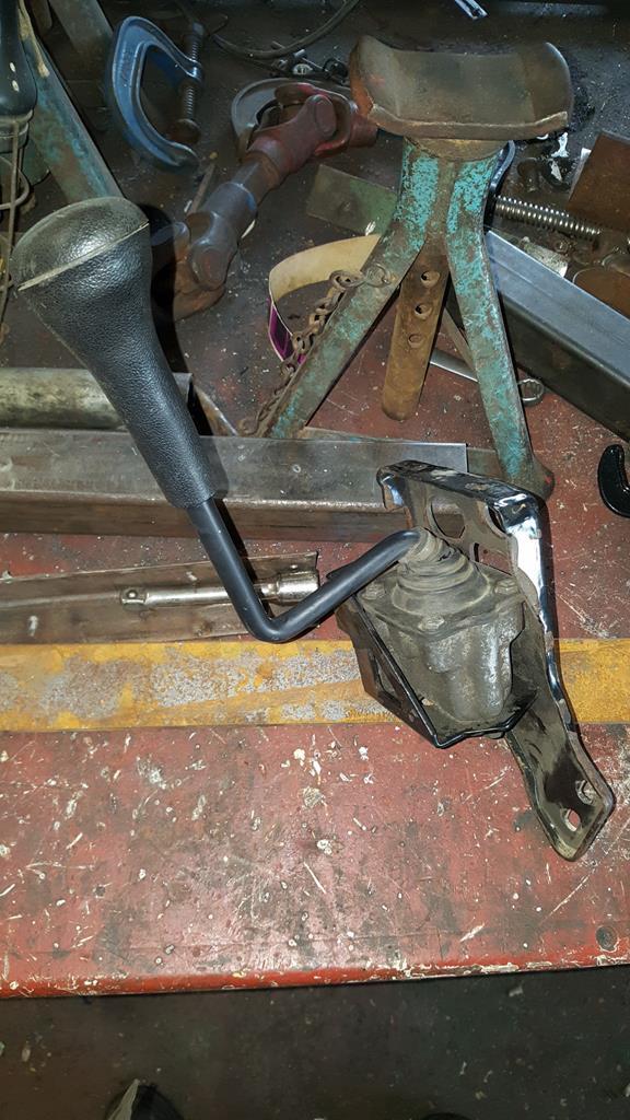 It needs to go somewhere around here, also the bracket looks really ugly so a new one is being made.. 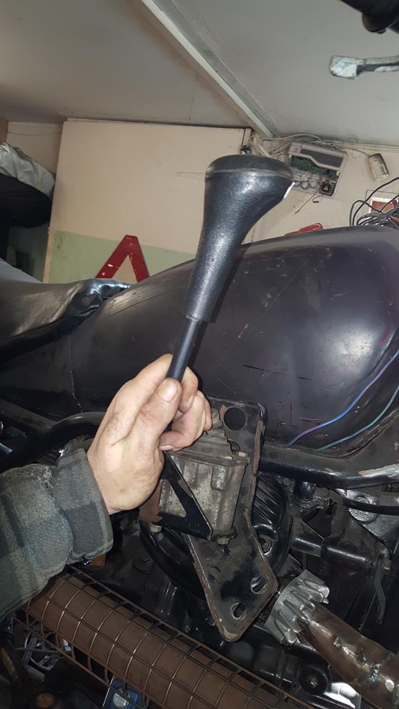 The fun bit is going to be making the rods that connect it to the transfer box, but luck might be on my side as I found an easy route through the frame, above the carbs that will require minimal bends to the rods.. Oh, a scrap pile raid produced all the rods I could need  Have a moody smokey picture of the MadTrax 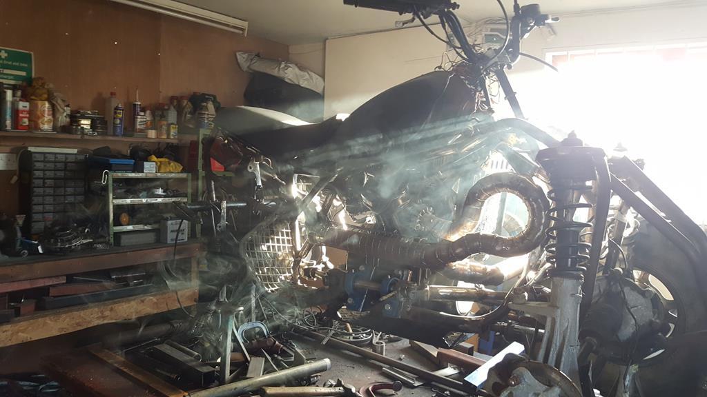 |
| |
My YouTube Channel www.youtube.com/user/UkWheelHorseBlokeQuote - D'you know, it's people like you, doing totally brilliant and pointless stuff like this that gives me a little hope for humanity |
|
|
|
|
Jan 17, 2018 21:11:24 GMT
|
I needed a better looking bracket to mount the transfer box shifter stick as the Quadzilla one was too big and very ugly. I'm sure you can guess which one is the new one 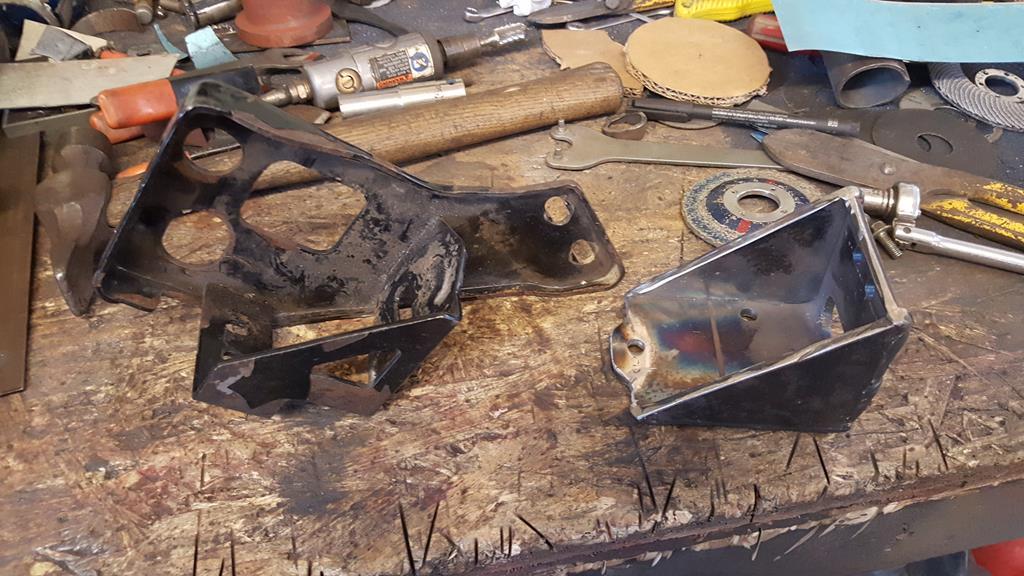 A view of the underside.  Shifter bolted in. 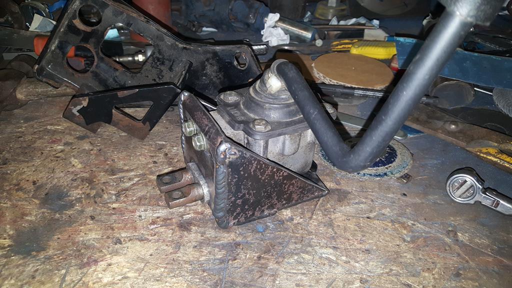 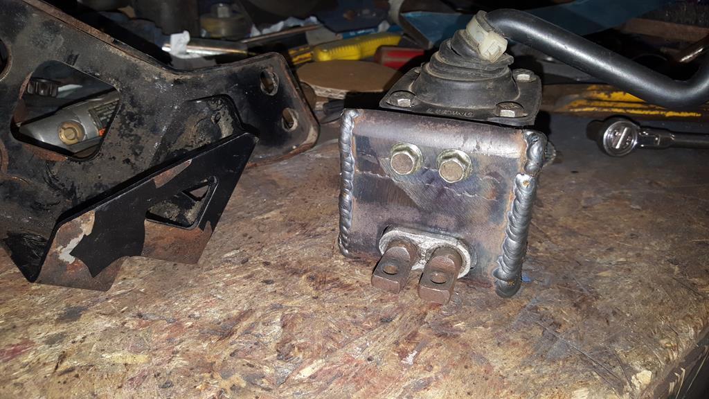 Still not quite sure where to mount it on the frame at this point, so I welded a couple of bolts to some blue steel bar. 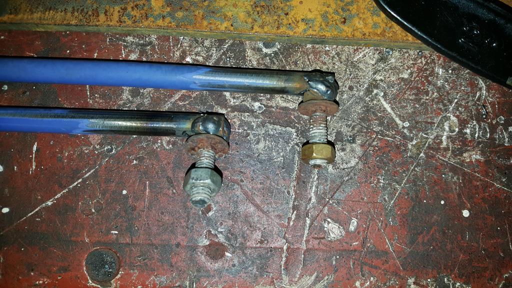 Very long bits of bar 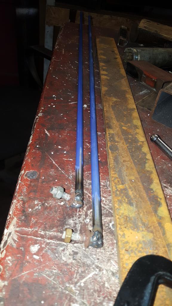 With the "bolt ends" of the rods stuffed through the frame and bolted on the TB levers, I could see there was a fairly straight run to connect the rods to a "next to tank" mounted shifter... But then I found out all the shifter marlarky fitted nice just above the exhaust, tucked into the frame a bit.. 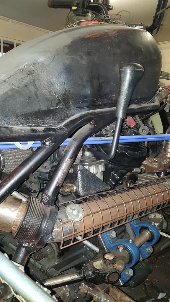 Just enough space to get the connecting rods on. 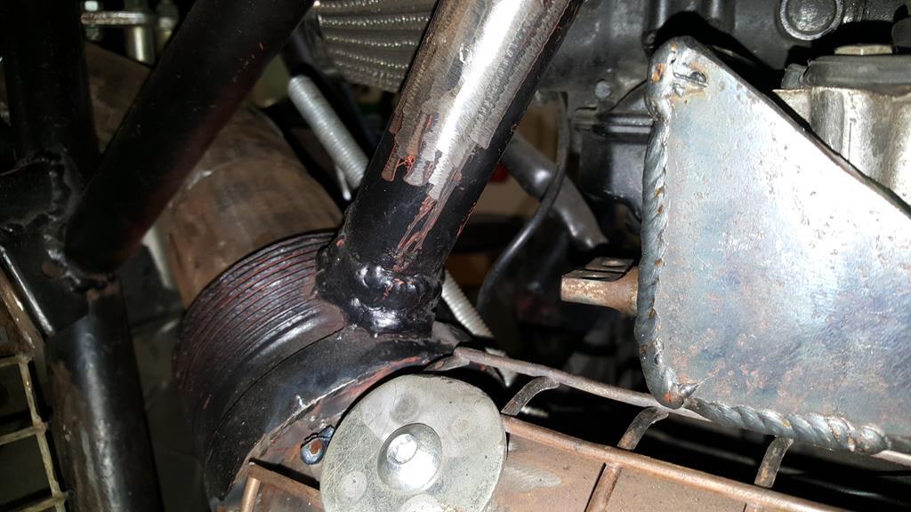 With one shifter box mount thingy done, the rods were shortened a bit, had a few bends put in and a bolt welded on the other ends.. It's a bit crude, I may re do the rods with rose joints, but for now the shifter works very well, and you get a reasuring "thunk" sound as the TB goes into gear 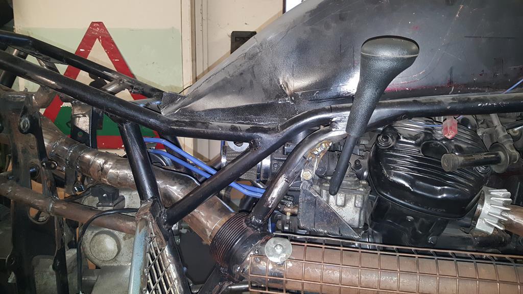 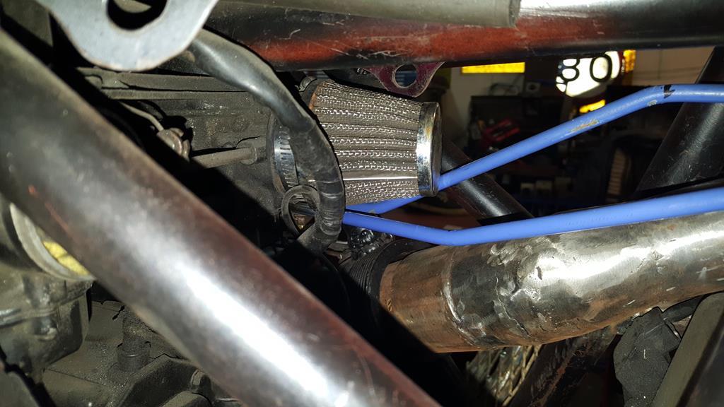 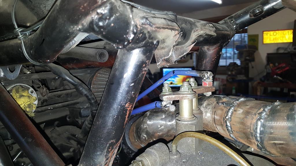 As you can see the shifter stick er... Sticks a fair way out from the gas tank.. A bit too far out for my liking.. 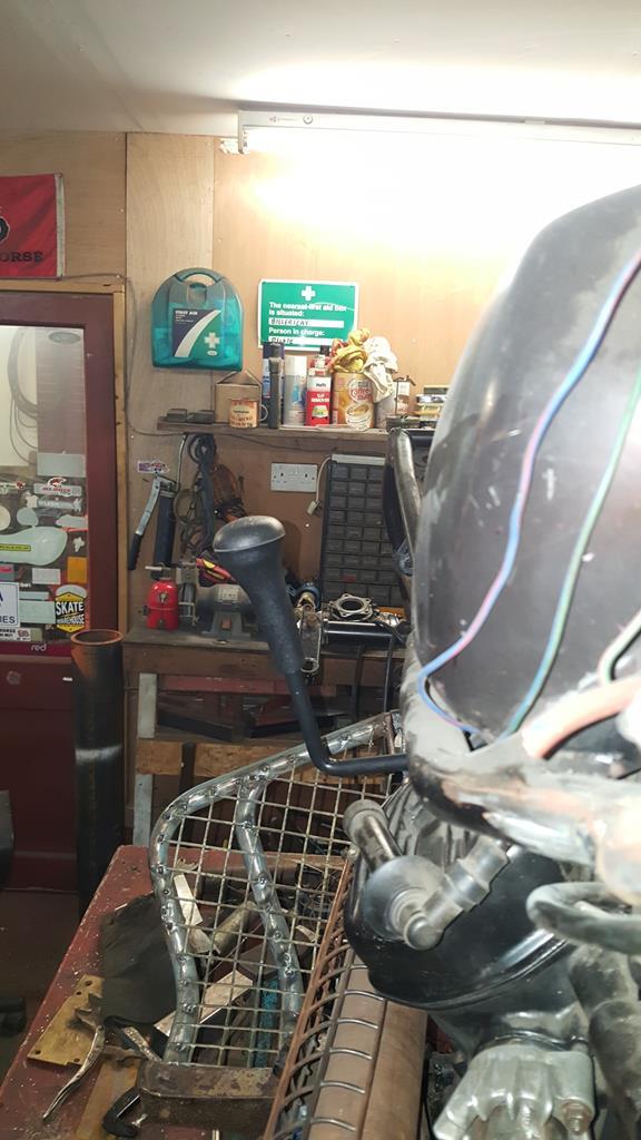 Before I could narrow it I needed to find out why the stick just fell to one side under the weight of it's self. Once cracked open I found two springs were missing that that should hold the gear stick in the middle.. Not being able to find any compreession spring in the workshop that were the right length, width and strength I found a couple of bit of clear fuel pipe work just as well 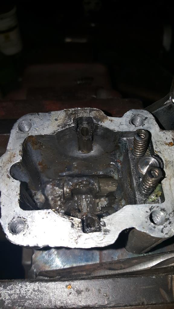 Just over an inch removed from the shifter.. Both halves were V'ed before welding back together to give maximun strength.. It looked quite nice once the welds were ground down nice and smooth 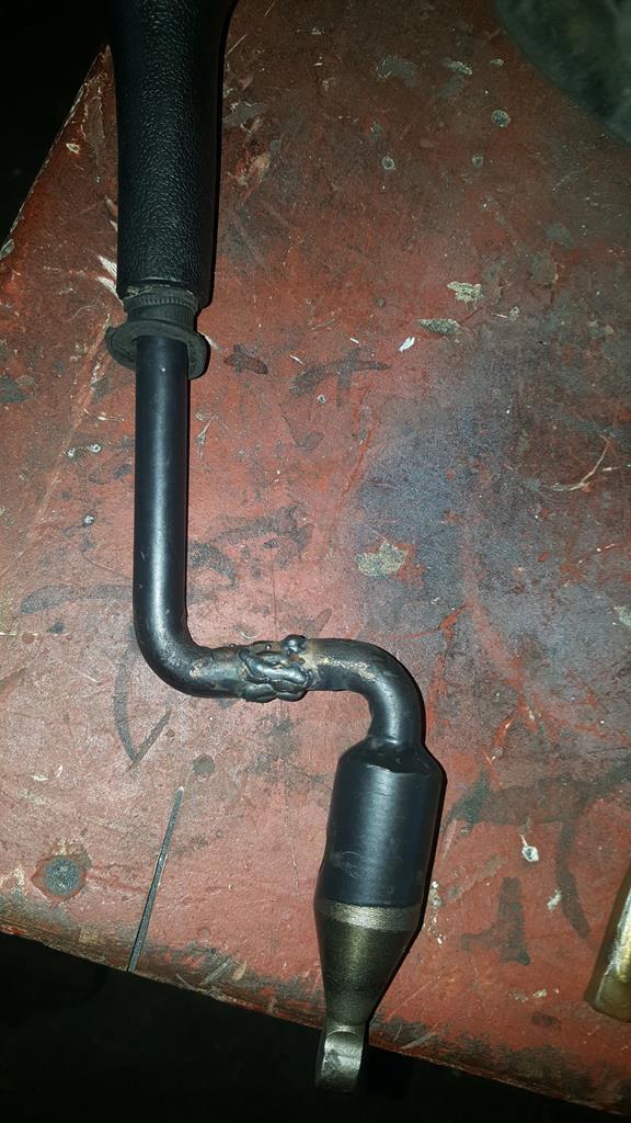 Bolted back on to the frame, but I don't like the look of the shifter knob, it's more "Montego/Maestro" than MadMax, but thanks to Nigel I have something a bit er... Different to graft on... 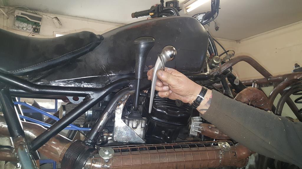 Yes it is what you think it is... A titainium hip joint 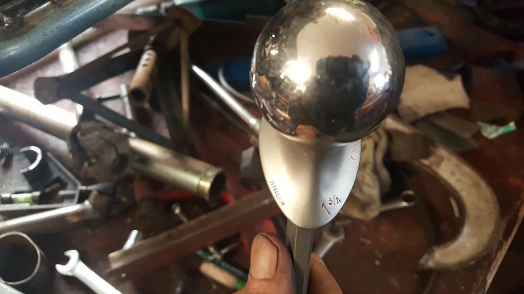 Now's a good point to drop in the latest MadTrax video.. Enjoy |
| |
My YouTube Channel www.youtube.com/user/UkWheelHorseBlokeQuote - D'you know, it's people like you, doing totally brilliant and pointless stuff like this that gives me a little hope for humanity |
|
|
|
|
Jan 17, 2018 21:20:09 GMT
|
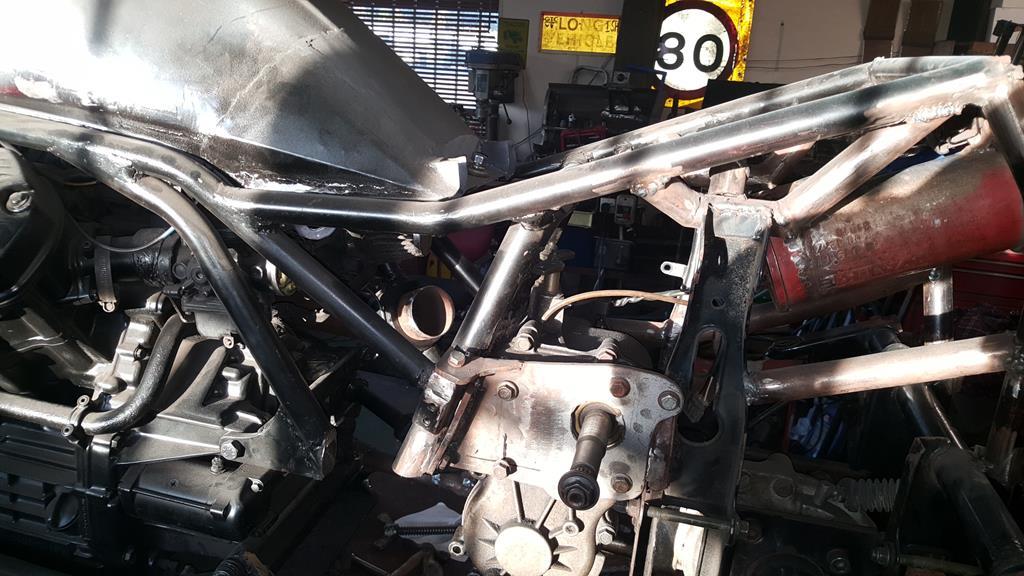
Well, a bit stuck on the drive train at the mo.. The Honda Silverwing final drive/90 Deg thingy I was planning on using just won't work! I did the maths on sprocket sizes to work out the 5 - 1 ratios I would need and the big sprocket would need so many teeth that it would be nearly a meter diameter! Price wise it would be very much the wrong side of £1000 and the sprocket would be so big it would cut the quad in half! So.. some more thinking needed.. I need a strong 1 - 1 ratio 90 Deg drive that will fit in the rather small space available! Sooo... What to do next.... Some welding me thinks At the back where the new tubes meet the Quadzilla suspension mounts it looked ugly as I had just cut the tops of the mounting panel off.. A bit of cutting and welding later had a couple of bits of box welded in just above the anti-roll bar tube.. That looks better and stronger 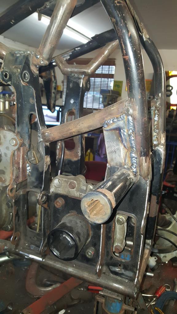 Part of the plan has always been to box in the pressed steel suspension mountings as I hate the look of pressed steel, and they never looked strong enough anyway! Starting with one of these, a bit of tube with washers welded on both ends. 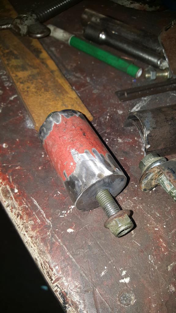 Which happens to be a perfect fit inside a thicker bit of tube that has been cut in half.. 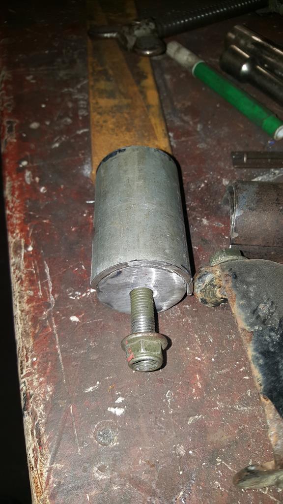 Bolt it to the suspension mounts and you have an ideal way of making sure all the bit's of half moon tube fit in the same places.. 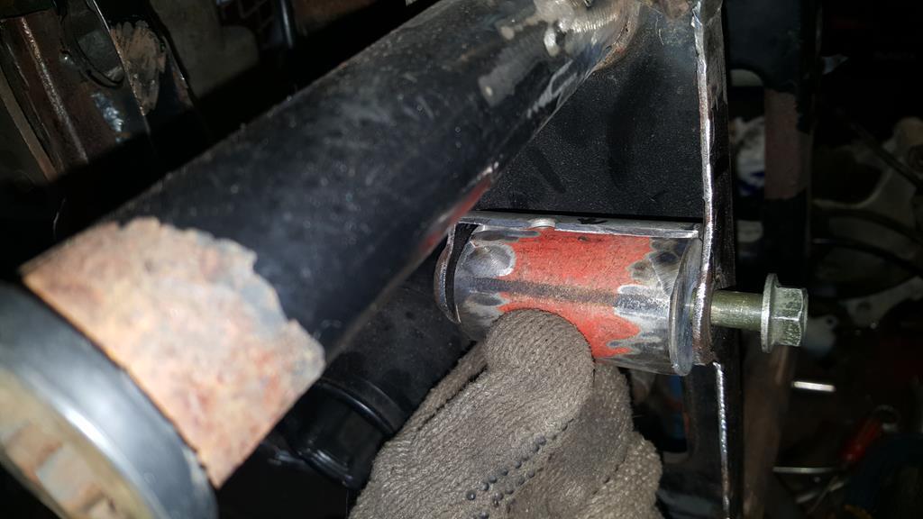 A bit of tack welding later.. 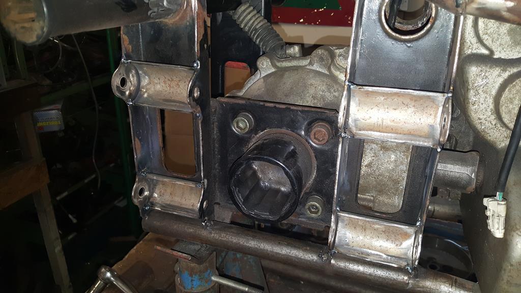 Best check for clearance, plenty of and more travel than will ever be needed 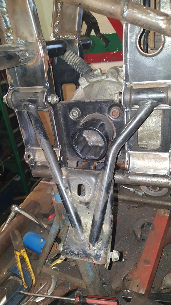 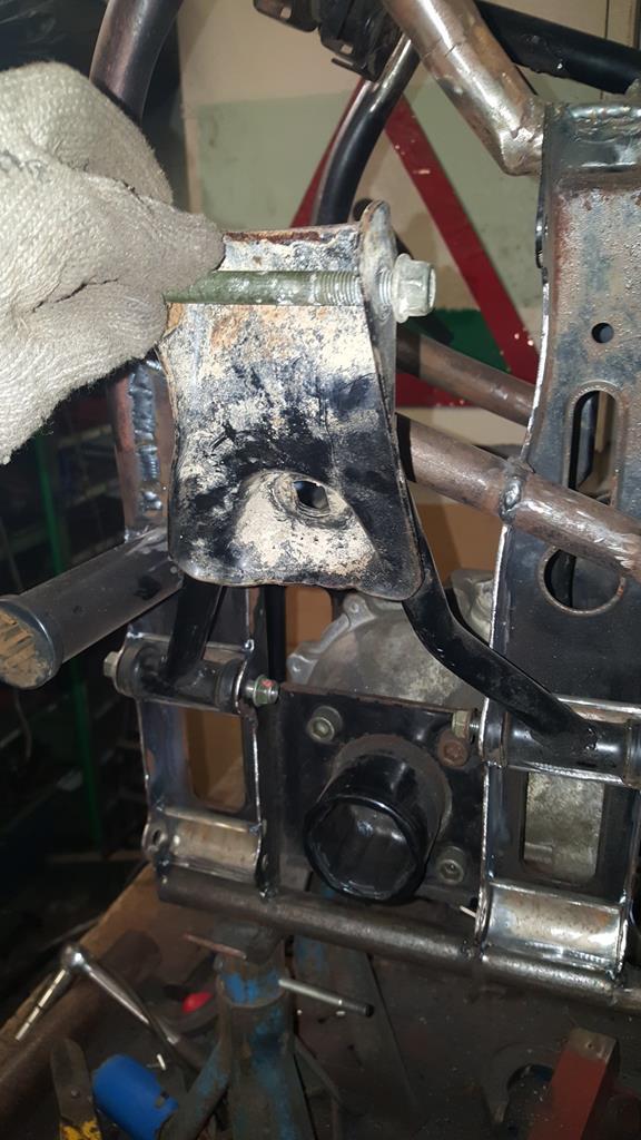 Now to fill the gaps, the top of this speaker stand is about the right thickness. 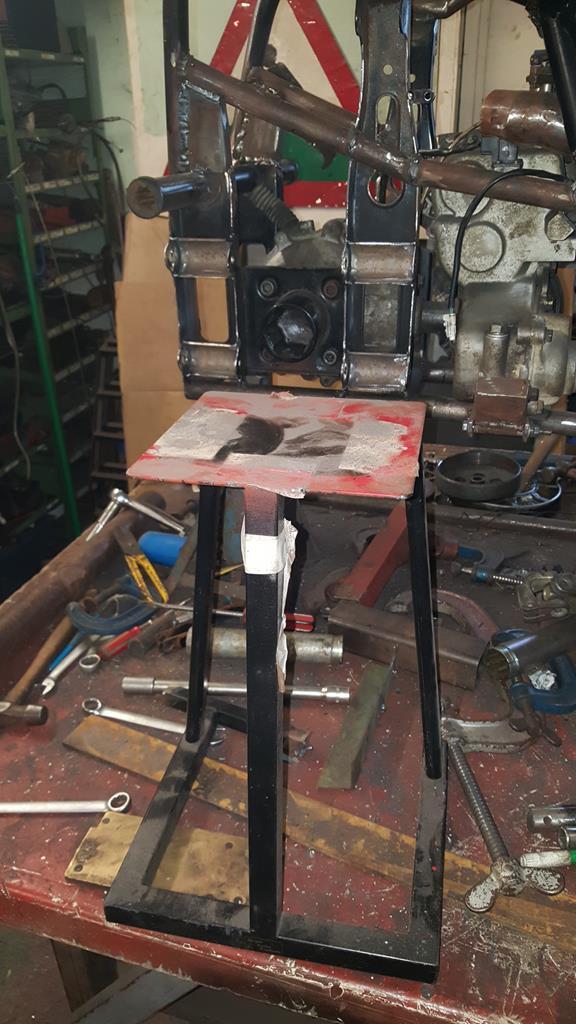 Four plates cut to size and tacked on plus a template for the next panel.. 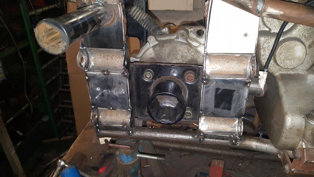 The right side almost done.. A few welds need a clean up, and a few of the welds won't be done until the frame is stripped and on it's side.. I hate welding upside down and I'm rubbish at it! 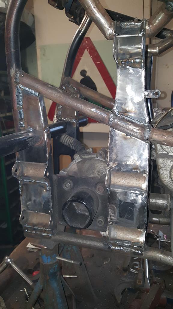 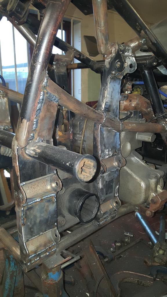 Best make a start on the other side, templates cut out.. 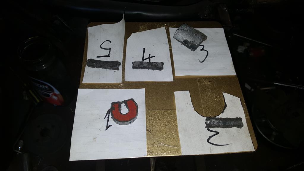 And marked out on steel... It's a good job speaker stands come in pairs 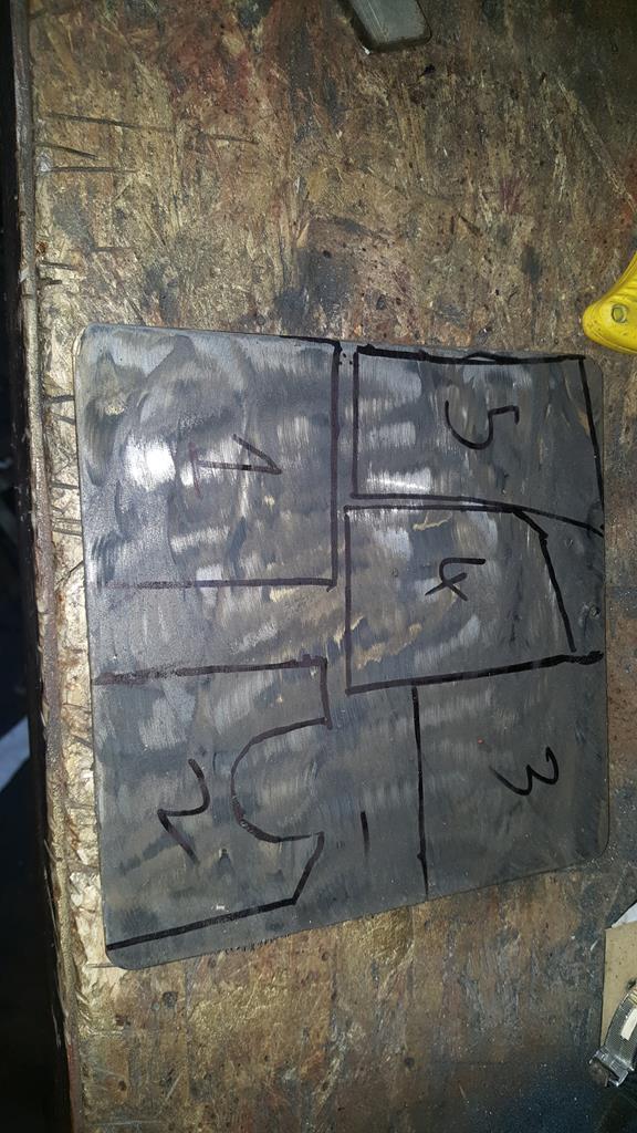 |
| |
My YouTube Channel www.youtube.com/user/UkWheelHorseBlokeQuote - D'you know, it's people like you, doing totally brilliant and pointless stuff like this that gives me a little hope for humanity |
|
|
|
|
Jan 18, 2018 13:17:33 GMT
|
It's definitely a thin line between bonkers and genius, but I think we'd all agree you're just the right side of the line! |
| |
|
|
|
|
|
Jan 18, 2018 21:59:29 GMT
|
It's definitely a thin line between bonkers and genius, but I think we'd all agree you're just the right side of the line! Indeed. But only just! |
| |
|
|
|
|
|
Jan 25, 2018 11:38:51 GMT
|
|
That gear stick is just awesome!!
|
| |
|
|
|
|
|
|
|
It's definitely a thin line between bonkers and genius, but I think we'd all agree you're just the right side of the line! The right side of the line eh.. That's good to know as my Wife often wonders It's definitely a thin line between bonkers and genius, but I think we'd all agree you're just the right side of the line! Indeed. But only just! Only just is close enough for me That gear stick is just awesome!! It's not something I have seen done before, maybe it's because "I'm close to the line", that I'm even thinking of doing it... Then again, how many people have a hip joint to hand Quite a bit to report, I have made a good start on the left side with the suspension mount strengthening.. When I put the TB in I had to cut a bit of tube out, so back in it went.. 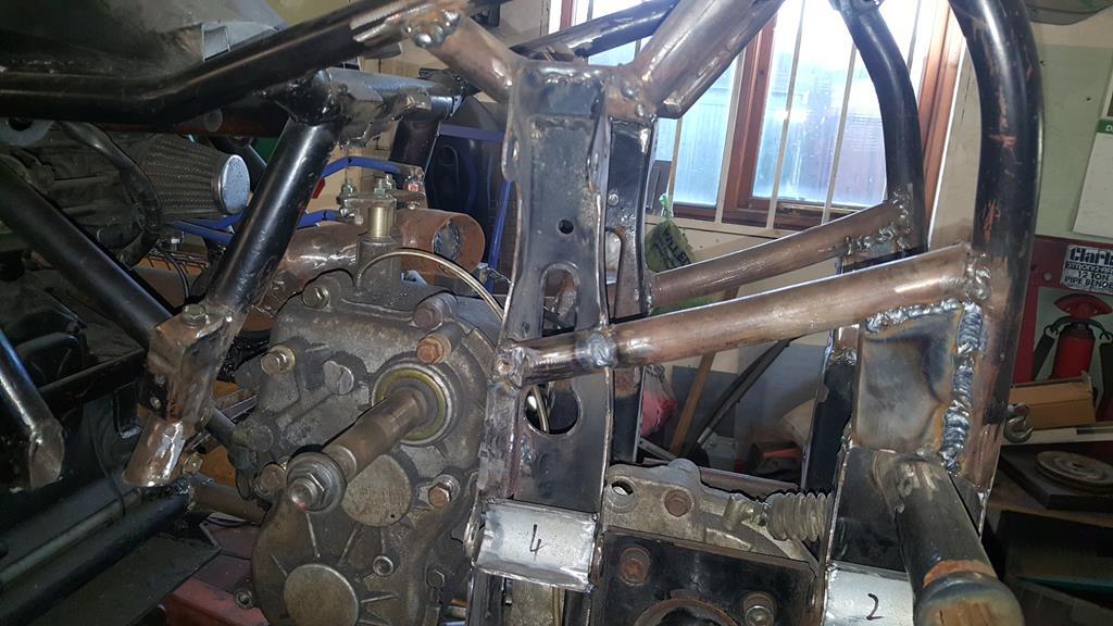 A close up. The captive nut is for the TB side mount. 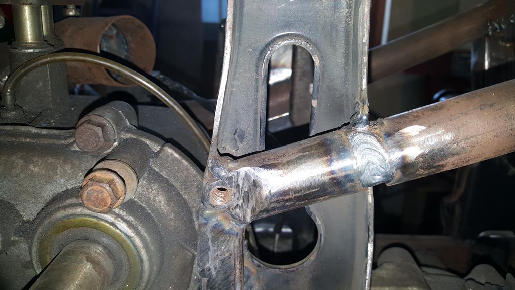 Only a couple of small plates to go in at the bottom and a lot of welds to grind down.. 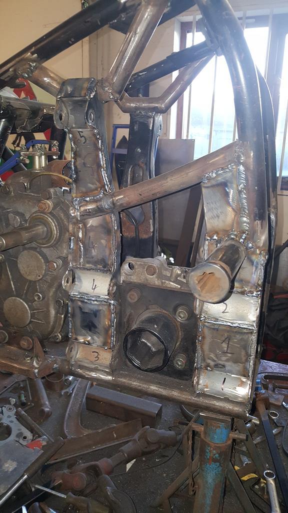 To try and keep things in order (must be a first) here's part 17 of the build. To finish off the strengthening on the left side I needed a couple of small plates to go at the bottom. Due to the small size of the holding them in place just wasn't going to work without setting fire to my fingers, so I welded a couple of small off-cuts to the plates to act as temporary handles. 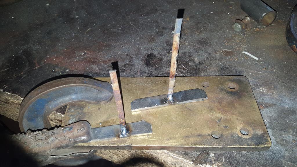 Plates tacked in place.. 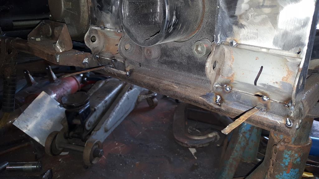 Once the plates had been fully welded on the time had come to tackle a job that thus so far had caused me lot's of head scratching.... Removing the rear diff/final drive thingy.. 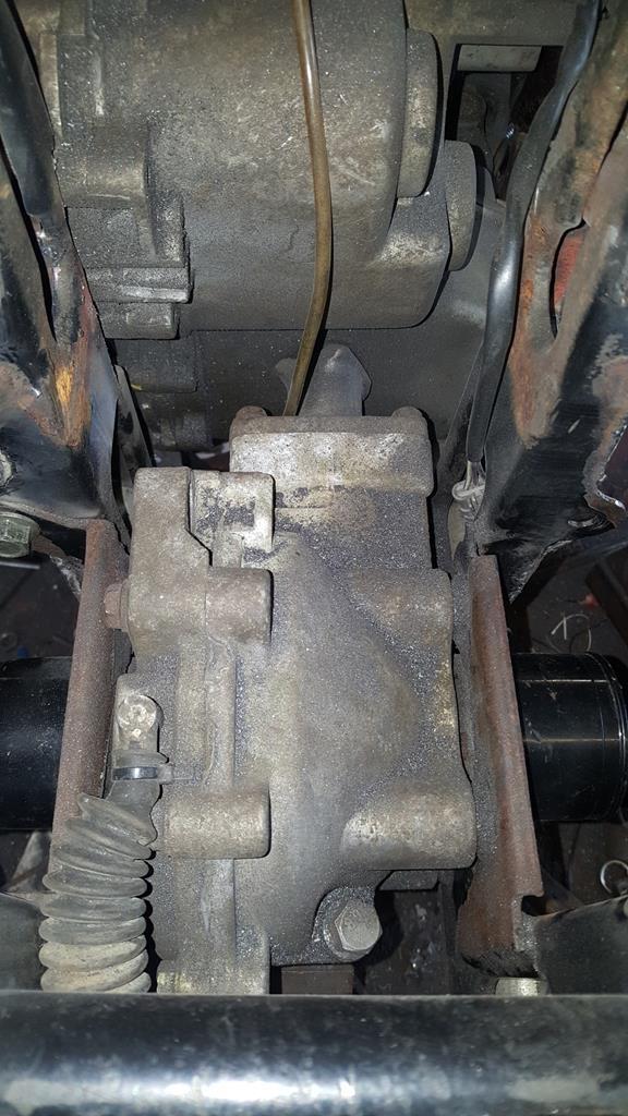 The right side already had a removable plate.. 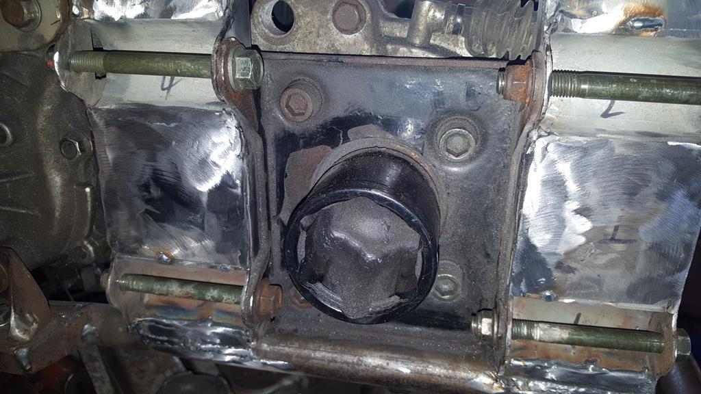 The left side didn't, but if I could make it removable them I might stand a chance of getting the rear end out.. HHmmm... Some nice welds to cut through! 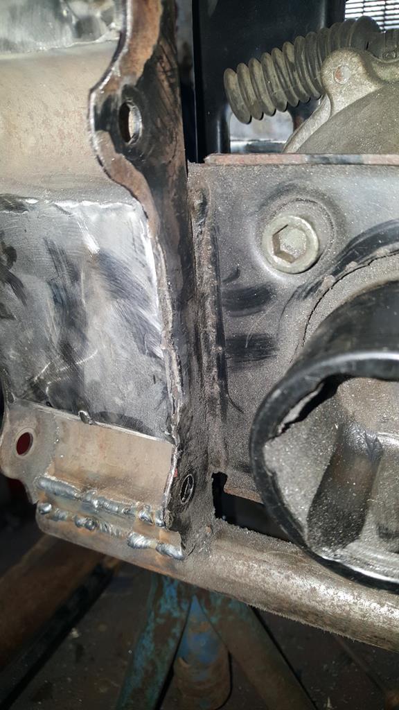 But before I started cutting metal a template was needed! 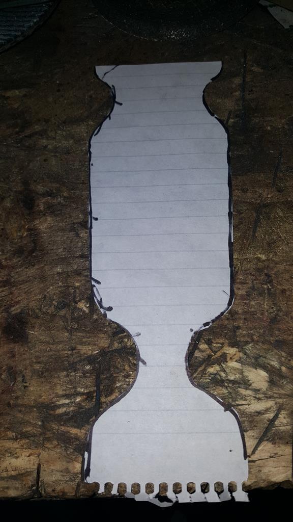 Ok, I needed the bit's marked F and R but the off-cut in the middle is a funky shape 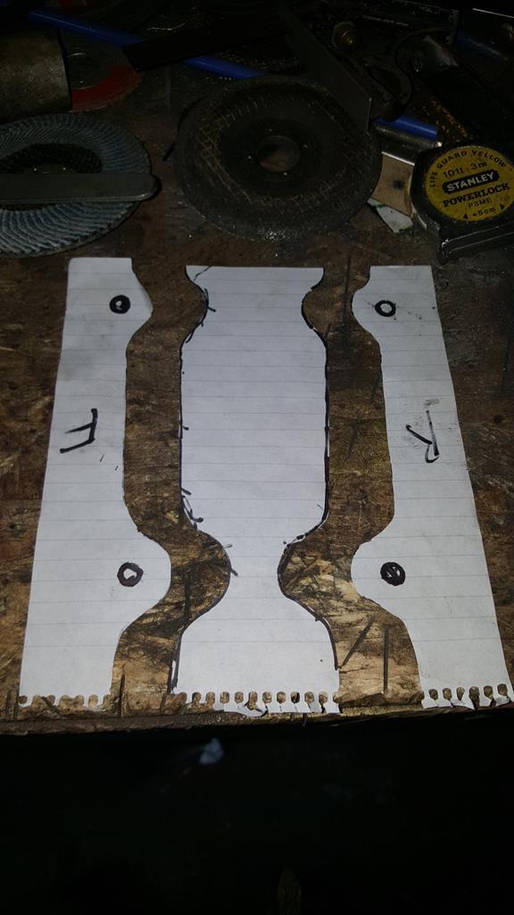 This was part of the Quadzilla front end.. Some cutting needed but it's just the right thickness for what I need. 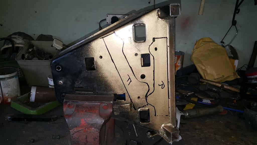 Here's the plate cut out of the frame and the extra couple of bit's of steel which will make the plate removable.. 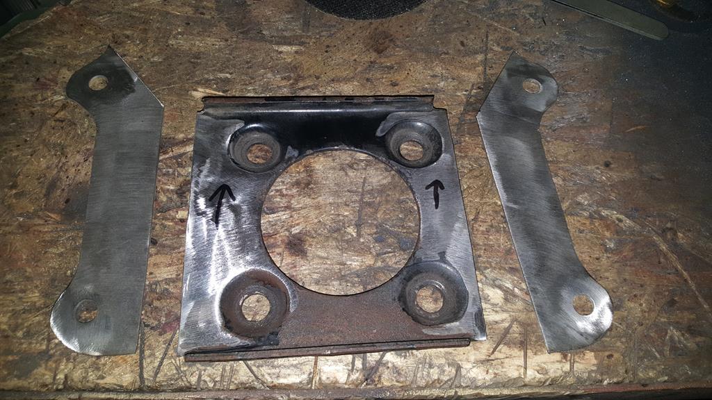 With all the parts bolted back on some tack welds were added. 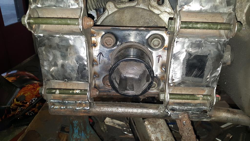 Back on the bench the now removable plate was clamped around some box and a bit of angle to hold it all square while I zapped the joins up.. Don't think it will be moving now 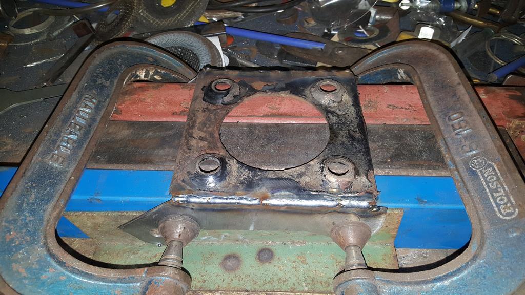 |
| |
My YouTube Channel www.youtube.com/user/UkWheelHorseBlokeQuote - D'you know, it's people like you, doing totally brilliant and pointless stuff like this that gives me a little hope for humanity |
|
|
|
|
|
|
Now to try and get the rear end out.... Eeerrrr! 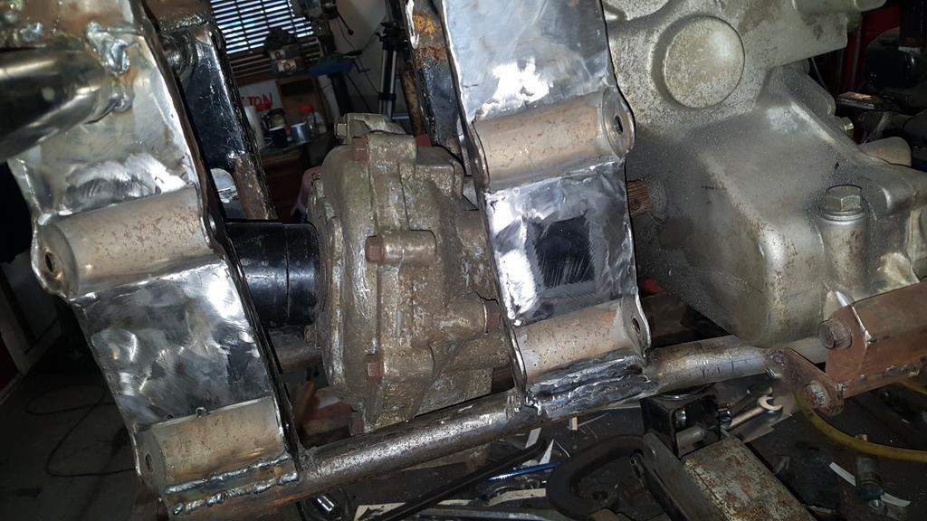 Ummmm! 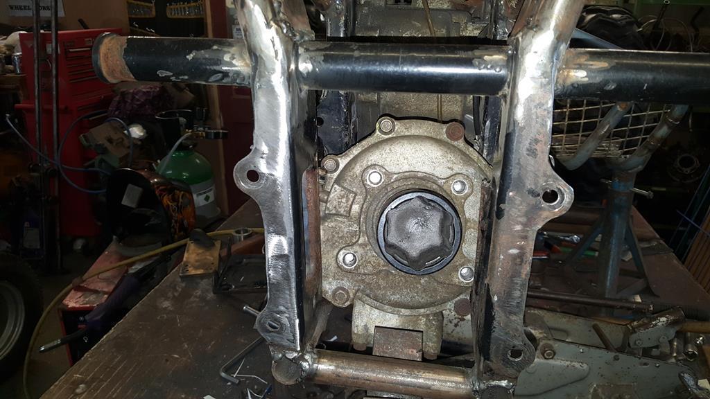 Until eventually I was left with this open space... 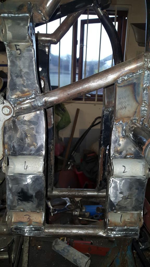 Which was only possible once I had cut this bit of tube out the frame... Another bit to make removable!  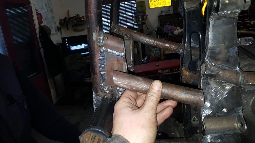 The rear end on the bench.. 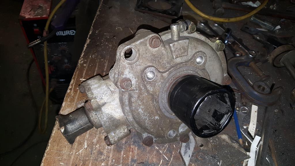 Rob picked up a wire brush and started to attack it to see what it would come up like.  Not bad but I fear some mechanical cleaning help is needed..... Now where did I put those wire brush cup thingys that go in the drill??? 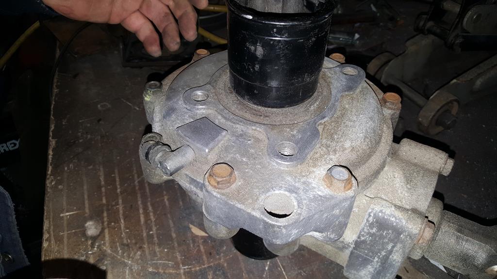 More metal work.. The removable bit needed to be made bolt-in-able, so some more metal was added.. 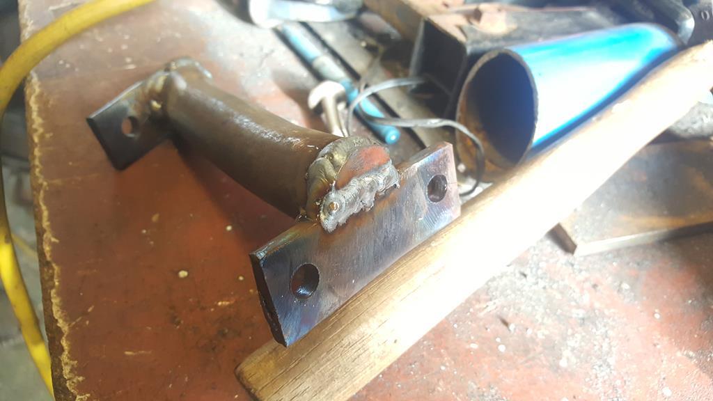 Some captive nuts would be handy to bolt it on, but I didn't fancy burning my fingers trying to hold the nuts in place while welding... So may I introduce to you all the sacrificial pencil 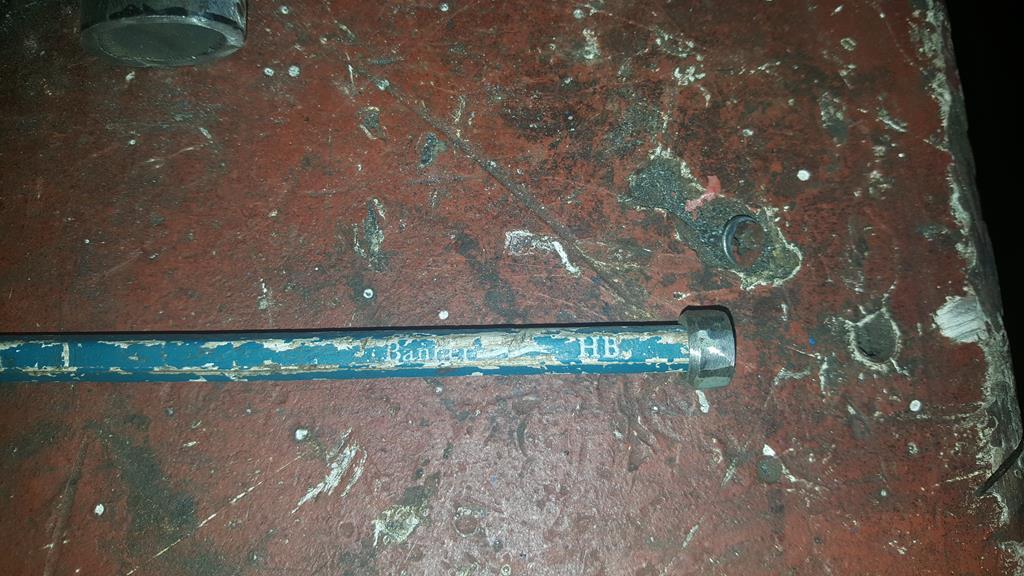 Not only does the pencil screw into the nut very nicely, any pencil that burns off is easily removed from the thread 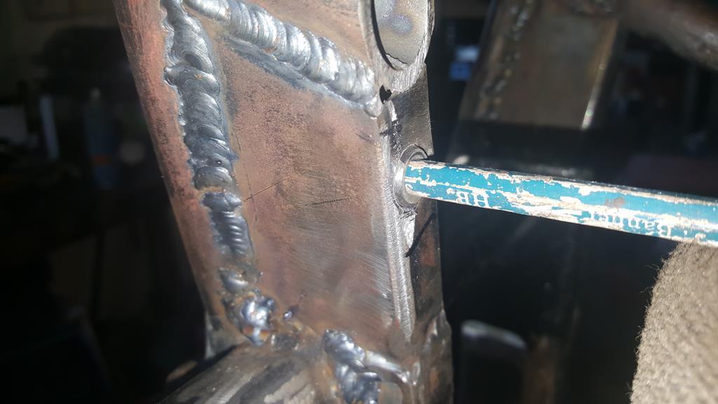 Welded in with not a welding splat on the threads in sight Ok, this pic may be of the opposite side to the above pics, but it does point out the big hole in the end of the tube where it's been cut off.. 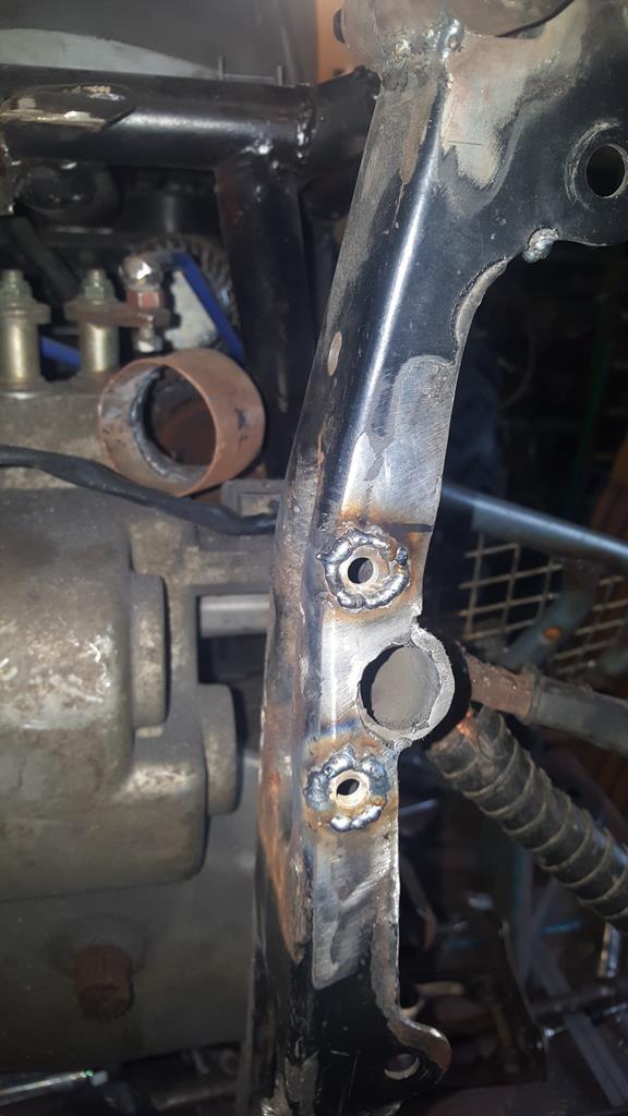 To fill the holes I found a couple of washers about the right, cleaned them up and clamped them onto a bit of brass plate. 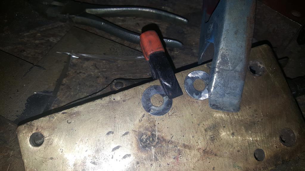 The holes in the washers were then welded up, the weld won't stick to brass.. Then a couple of "trimmings" were tacked on to give something to hold on to. 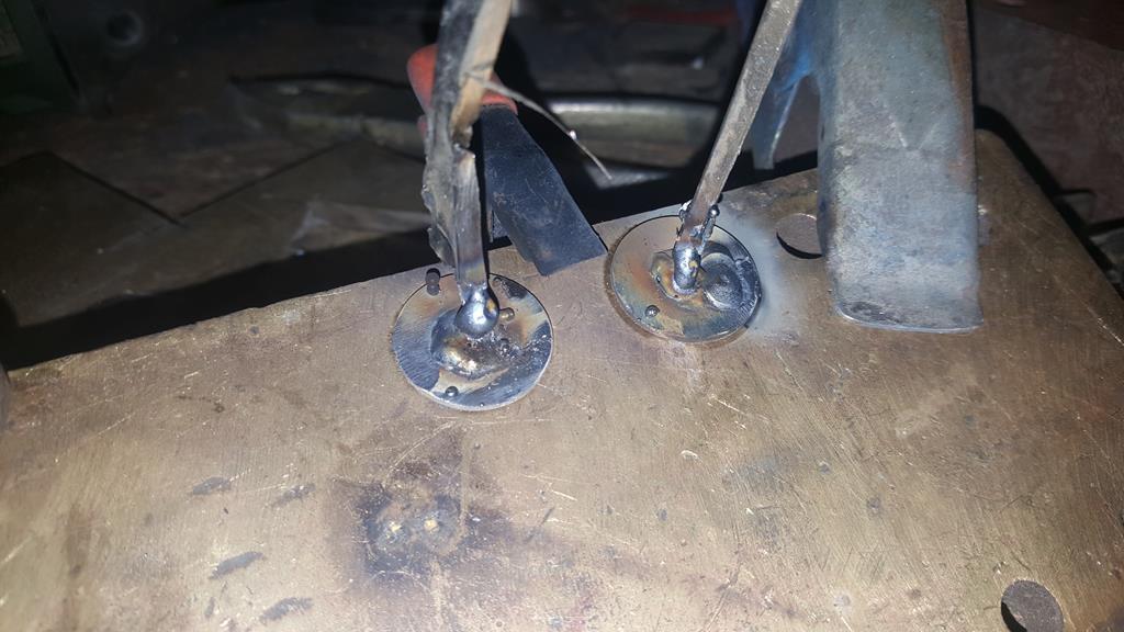 Once removed from the brass they looked like this.. 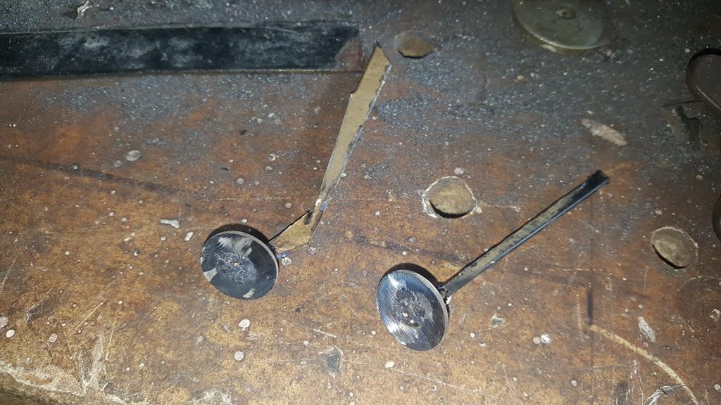 Washers welded in.. 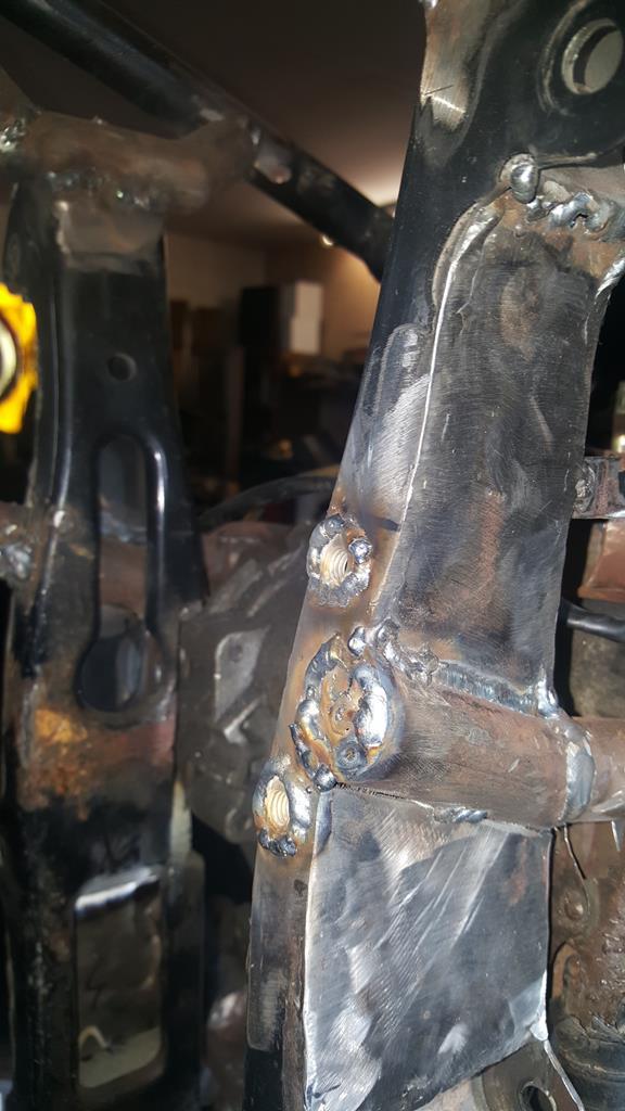 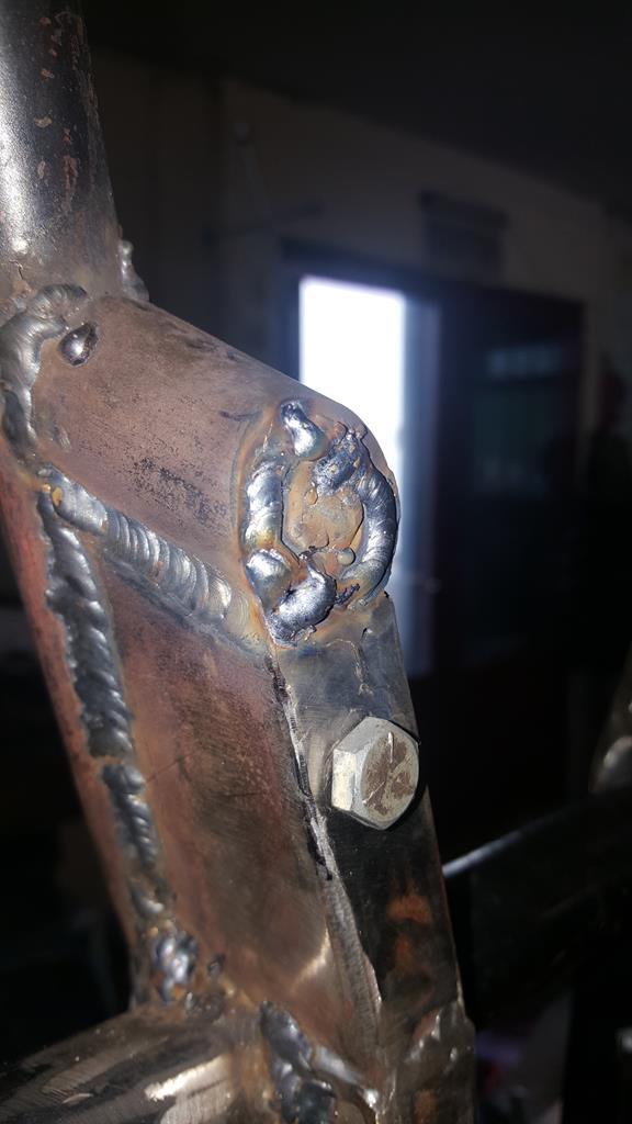 And once the welds had been cleaned back the removable bit was bolted back in.. 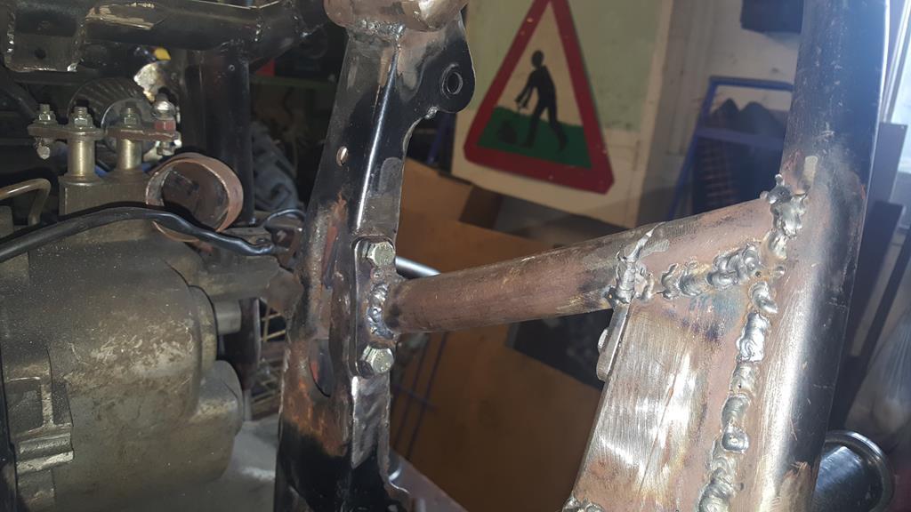 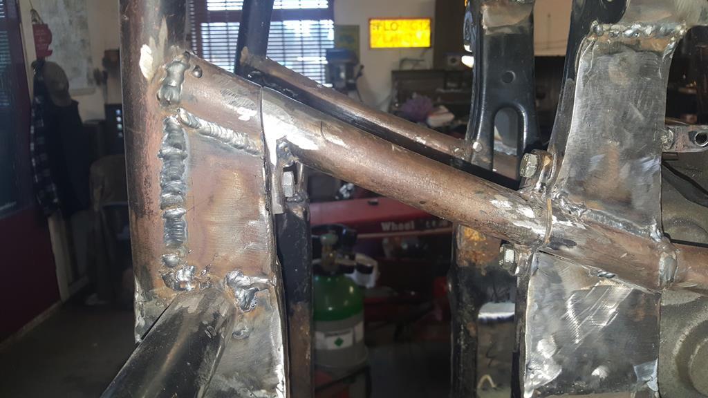 |
| |
My YouTube Channel www.youtube.com/user/UkWheelHorseBlokeQuote - D'you know, it's people like you, doing totally brilliant and pointless stuff like this that gives me a little hope for humanity |
|
|
|