Darkspeed
Club Retro Rides Member
Posts: 4,845
Club RR Member Number: 39
|
|
May 17, 2020 18:26:39 GMT
|
Thanks for the explanation. I saw the Honda engine but didn't realize their suspension was also being used. Good stuff. Jojm Only the engine has anything to do with Honda - All of the suspension is Litton - the reference over is because there are Litton chassis for Honda engines - Alfa Engines - Lancia Engines - Ferrari engines - and due to the different physical sizes and layouts of those engines the geometry is subtly different. And of course there are the Strut chassis as well as the rarer double wishbone types like mine. The Alfa engine Corse-i chassis is known to have a weakness in that the rear wheels go positive in roll. |
| |
Last Edit: May 23, 2020 22:44:39 GMT by Darkspeed
|
|
|
|
Darkspeed
Club Retro Rides Member
Posts: 4,845
Club RR Member Number: 39
|
|
May 17, 2020 18:50:02 GMT
|
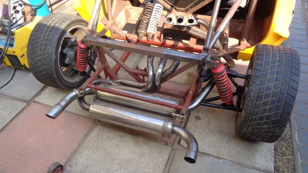
Shock mounting works. Remove bodywork and dump it in the front garden.  Break out the cutting discs and show it to the unwanted brackets 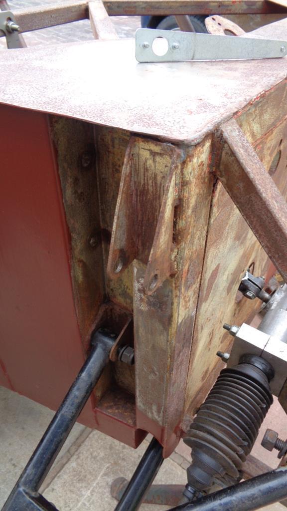 Chop at them as best you can and then lay waste to them with the 10 thou adjuster until they relent. 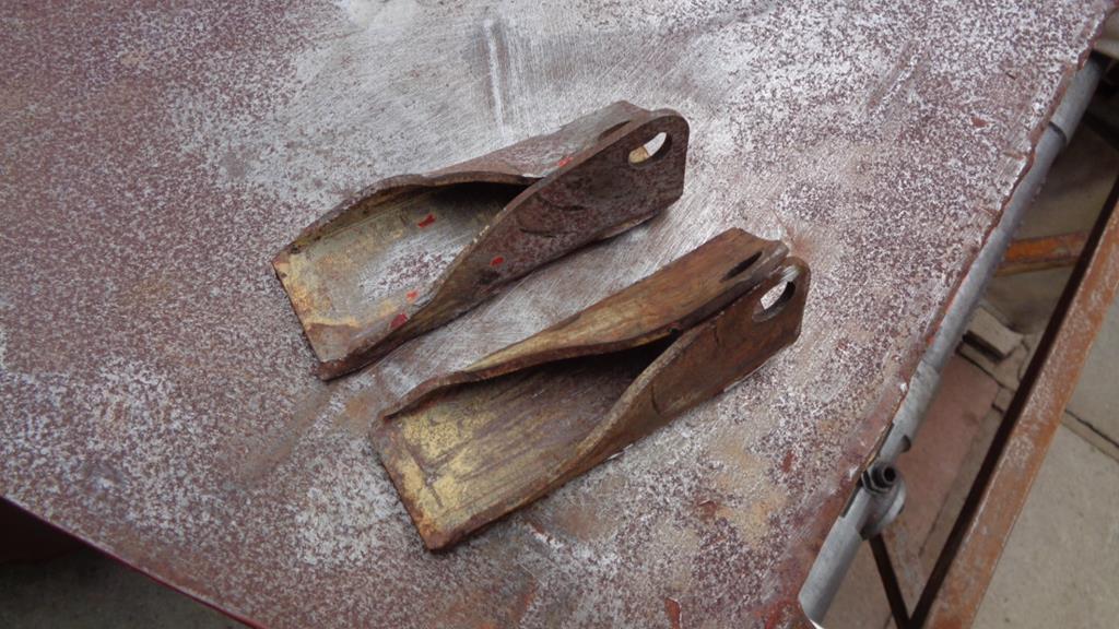 Grind flat and then survey the damage where the disc went a bit too far. 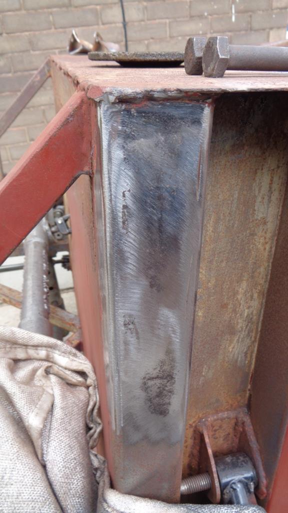 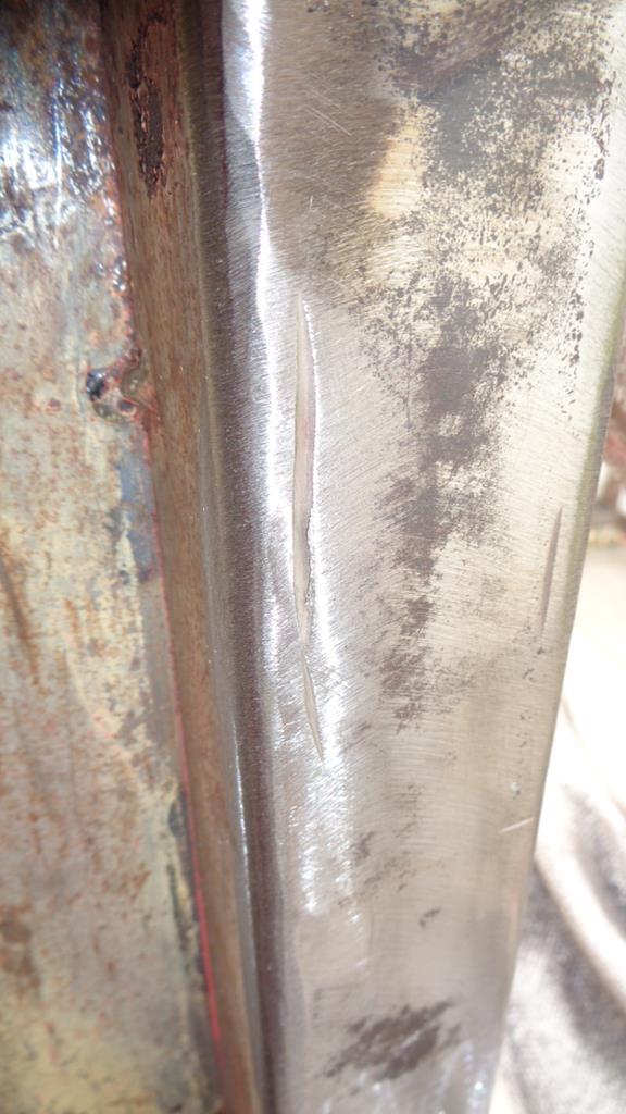 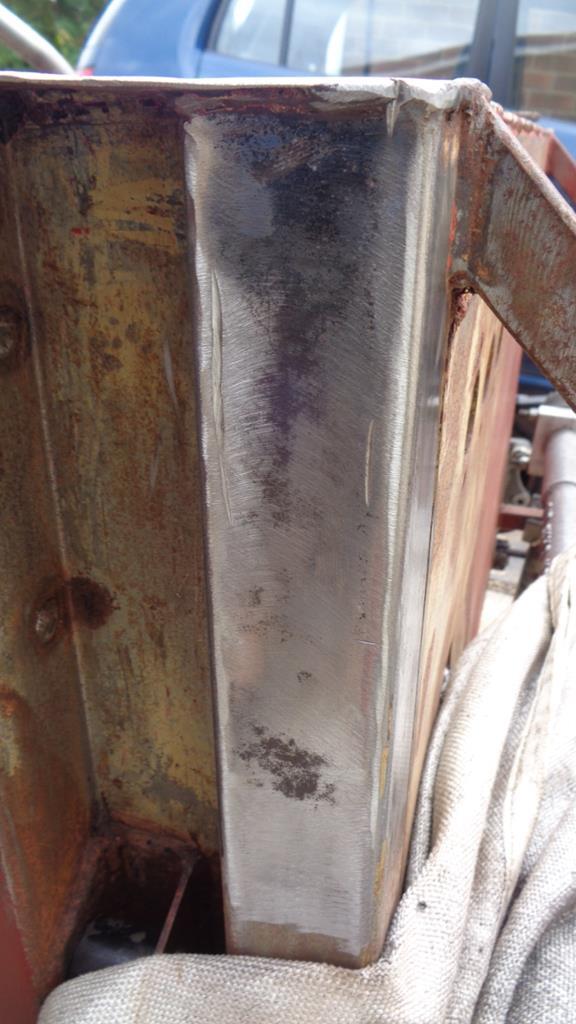 Make good. 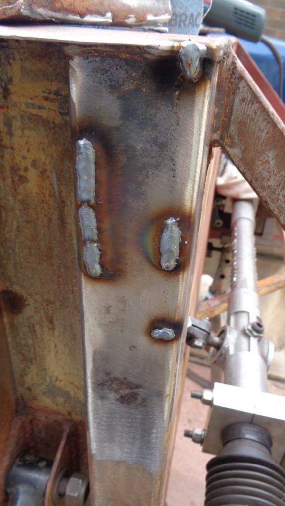 And then grind flush 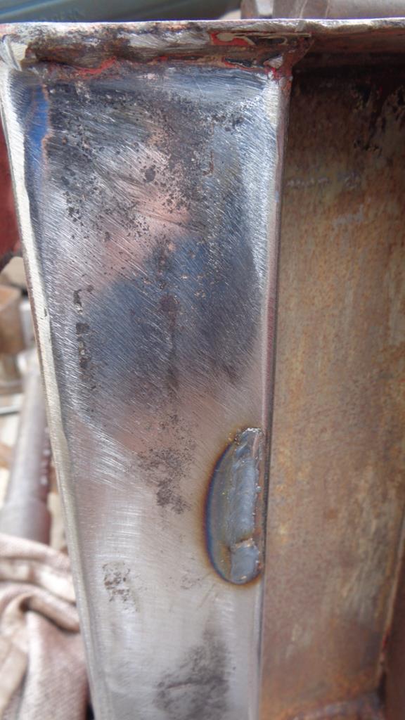 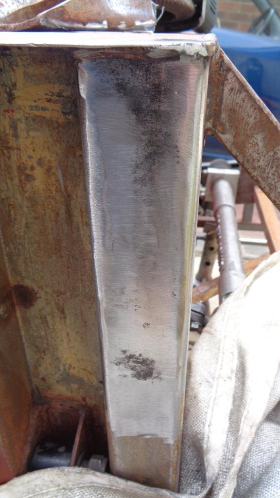 Spend a lot of time measuring and checking 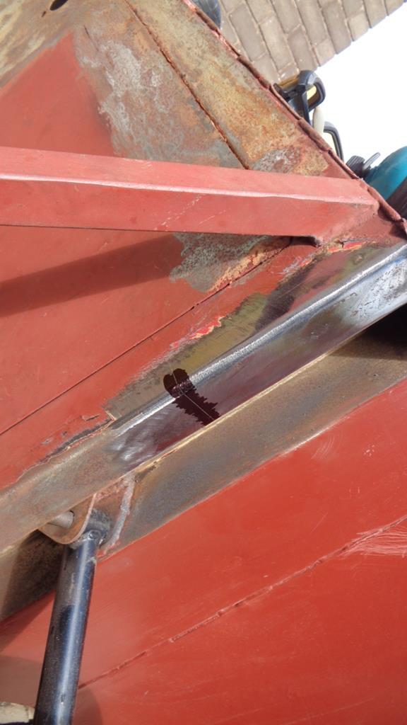 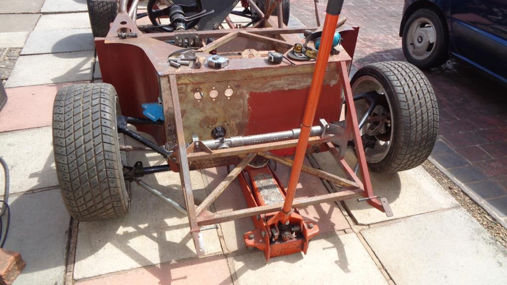 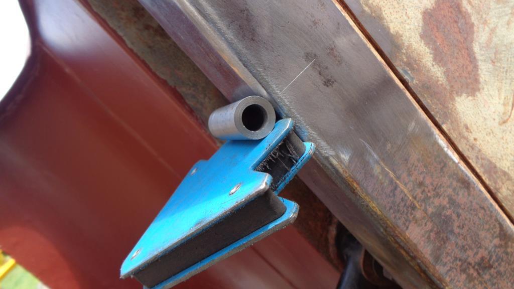 Then just weld them on telling yourself it does not really matter if they are not mm perfect as you have done it this way to have adjustable brackets so the actual mounting can be mm perfect. 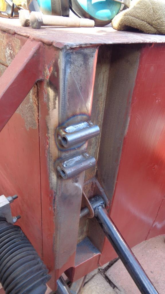 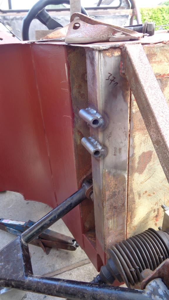 CAD next to design the mounting brackets |
| |
Last Edit: May 17, 2020 18:53:24 GMT by Darkspeed
|
|
Darkspeed
Club Retro Rides Member
Posts: 4,845
Club RR Member Number: 39
|
|
May 19, 2020 19:37:08 GMT
|
Spent a bit of time this evening drawing up the brackets for the front suspension. 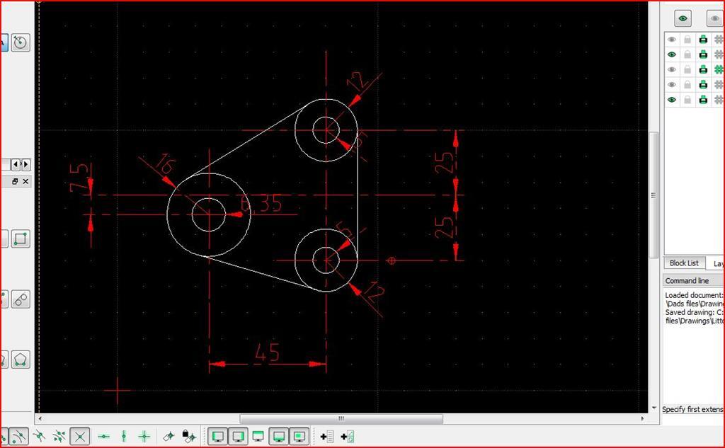 Marking up and cutting out next. The 7.5mm offset in the bracket allows for 20mm of suspension adjustment if mounted one way up or the other without any changes to the coilover setting. Will start them this evening tomorrow. |
| |
|
|
Darkspeed
Club Retro Rides Member
Posts: 4,845
Club RR Member Number: 39
|
|
May 22, 2020 19:30:41 GMT
|
Complete fail on getting a start on the brackets during week - so that's a job for the this Bank Holiday weekend that I have extended by a couple more days  I did treat myself though and place the order for the coil-overs - a couple of three weeks and they should be with me. One of the three big spends done just the wheels and brakes to go. I was hoping that this year would get all of the major items ordered but I have a feeling that the funds my be a little more limited than had been anticipated at the start of the year. Still there are more Gemini's than I am in need of cluttering up the place so maybe a bit more rationalising to raise the necessary funds will be required. As I will have the TIG fired up for some welding of aluminium for the coolant pipe work on the Gemini I may well start doing a bit on the fuel tank. Plenty to do. |
| |
Last Edit: May 23, 2020 13:22:54 GMT by Darkspeed
|
|
Darkspeed
Club Retro Rides Member
Posts: 4,845
Club RR Member Number: 39
|
|
May 23, 2020 19:30:28 GMT
|
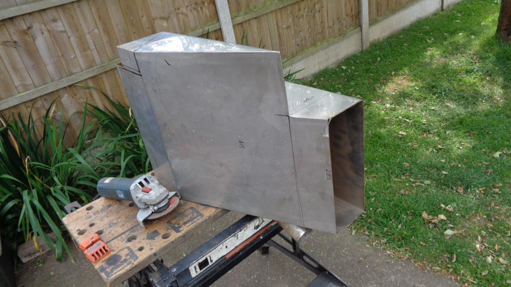
First job today was getting the brackets made for the front suspension so that I could fit a couple of old shockers to get the car rolling again to make a bit of room on the drive to back the Gemini out of the garage to make space so that I could do some TIG welding. One of the drawbacks of doing all these projects out of a single garage from the 1960's. Mark cut drill shape - Still have to take the shock mounting hole out to 1/2" - Will do that when I give the brackets a polish up. 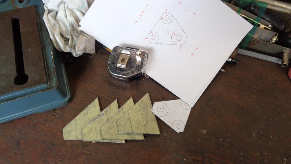 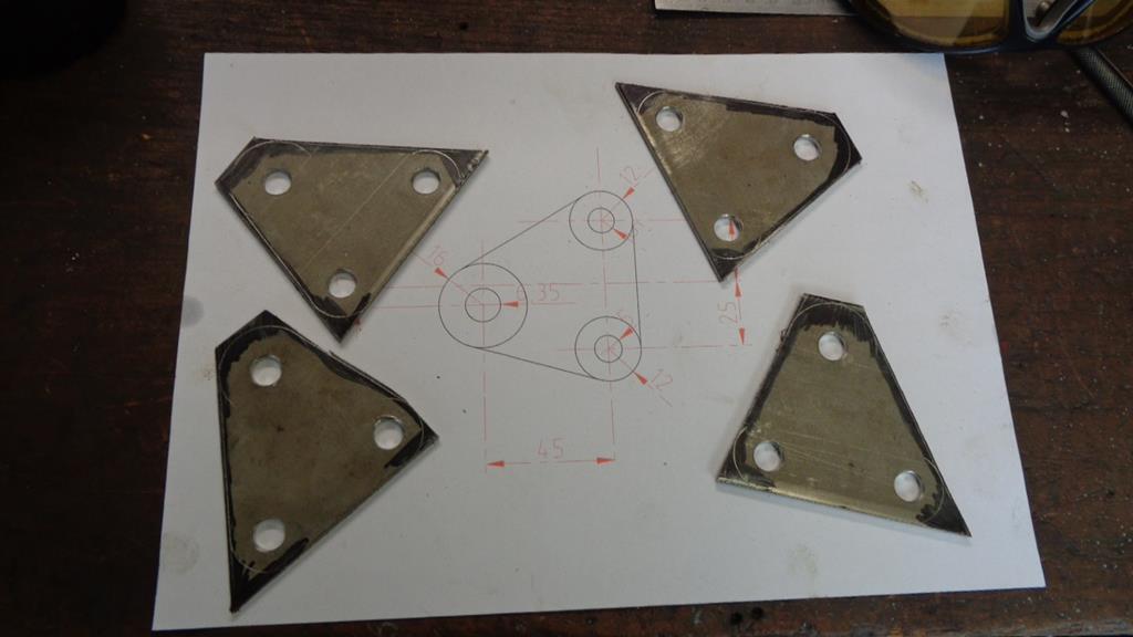 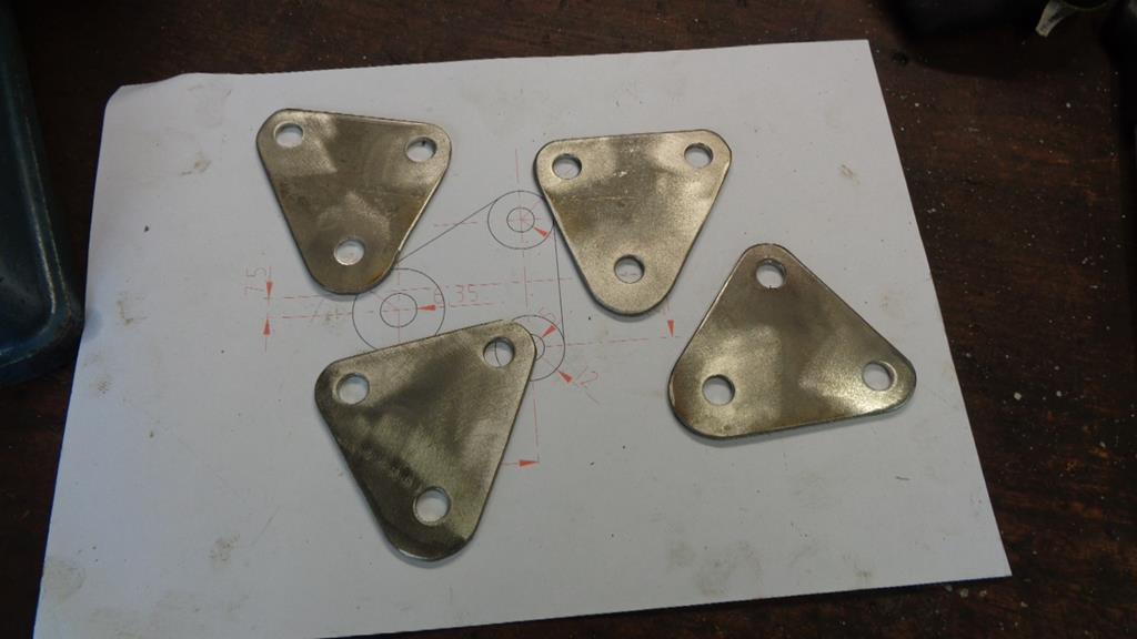 Fit brackets using an assortment of M10 odds and ends and drop the old rear shocks from the Grass tracker on it 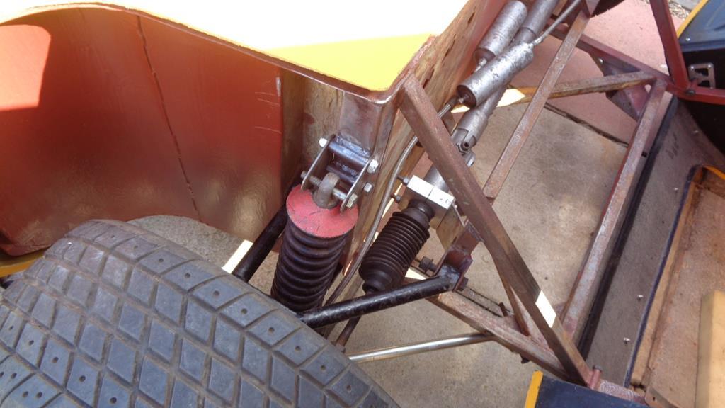 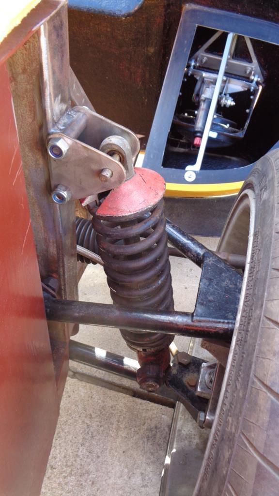 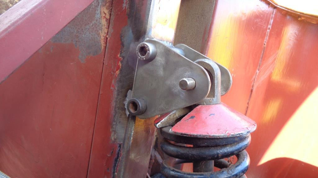 Back rolling again. Things to order this week - Bolts - Rivets. Start making a few alloy panels for it next. |
| |
|
|
|
|
|
|
|
|
You're good at this stuff...all very tidy and strong looking.
How do you cut the metal for things like those brackets: just a wheel on a grinder or something else?
Thanks, John
|
| |
|
|
Darkspeed
Club Retro Rides Member
Posts: 4,845
Club RR Member Number: 39
|
|
|
|
You're good at this stuff...all very tidy and strong looking. How do you cut the metal for things like those brackets: just a wheel on a grinder or something else? Thanks, John  If things are not going to take an age using hand tools then that's the path I like to take. |
| |
|
|
|
|
|
May 24, 2020 14:51:46 GMT
|
|
Looks great but there is no support above the top of the shock and there is a sheer point now on the bottom bolt pivoting about the current top bolt, I think for safety you need another mounting about 3" above the top current mounting with new side plates to triangulate it all.
|
| |
|
|
Darkspeed
Club Retro Rides Member
Posts: 4,845
Club RR Member Number: 39
|
|
May 24, 2020 19:04:20 GMT
|
Looks great but there is no support above the top of the shock and there is a sheer point now on the bottom bolt pivoting about the current top bolt, I think for safety you need another mounting about 3" above the top current mounting with new side plates to triangulate it all. Thanks Pete - I'm good with it as is for the time being - I think that the bracket would tear well before the bolts gave up in double shear, and the bracket failing assumes that the wishbone at the other end of the shock has not bent in half under the force first. Or the shocker not bent and snapped. It's a very small lightweight vehicle. |
| |
|
|
|
|
|
May 24, 2020 19:25:09 GMT
|
|
I think it's fine too, you don't need support above the shock bolt, and it can't pivot arount the bottom bolt. My only reservation is I would like to see some cross bracing between the two side plates to avoid any fore/aft flexing.
But as you say, it's a light car so I may be overthinking it.
|
| |
|
|
|
|
|
May 24, 2020 20:49:25 GMT
|
|
There should be some bushes between the mounting lip and the schock absorber but i assume you already planned to do that. This reduces the stress on the schockabsorber bolt. In general bolts should be tight otherwise the bolt load is shear and in general bolts do not like that.
Cross brazing which Mark suggests would make it stronger but you should stay away from the holes for the schokabsorber bold as these need some room to bend so the schockabsorber bolt is tight
From a construction point of view, next time i would weld the mounting points on the chassis a little higher so you can reduce the dimension between the ears. This will reduce the stress on the schockabsorber bold with a fair amount.
Following this thread, your work is of a high level with very nice welds and lots of improvements on the original work and it is a joy to follow
Keep up the good work!
Peter
|
| |
|
|
Darkspeed
Club Retro Rides Member
Posts: 4,845
Club RR Member Number: 39
|
|
May 24, 2020 21:47:31 GMT
|
To summarise. It's about two years from completion and the works above, as I detailed, are just temporary to get it rolling. The shocks are scrap off the Tracker the bolts just sundry ones I had laying about. There is a couple of grands worth of Nitrons on the way bespoke made to suit the 50mm gap between those brackets with large spacer bushes between the sealed rose joints which are clamped by S grade 1/2" UNF bolts - The scrap mounting bolts will be replaced with 10.9 M10 and torqued to FT - there will be no pivoting no movement no flexing. Its an 800kg flyweight of a car with 40/60 F/R distribution - My other cars use a bracket welded to piece of 25x25x1.5mm wall mild steel to mount the suspension to which is overkill! - Lotus 7 mounts onto a 7/16 bolt in single shear - they don't snap break or need massive support braces - when they get in a shunt the chassis goes not the mountings.  Mine is completely OTT for the application and further levels of OTT are just not necessary or happening. Not my first rodeo. |
| |
Last Edit: May 24, 2020 21:48:18 GMT by Darkspeed
|
|
Darkspeed
Club Retro Rides Member
Posts: 4,845
Club RR Member Number: 39
|
|
May 25, 2020 20:53:12 GMT
|
|
|
| |
Last Edit: May 25, 2020 21:02:32 GMT by Darkspeed
|
|
|
|
|
May 25, 2020 21:24:05 GMT
|
|
Is there room for a matching tank on the other side? I have a 7 gallon tank in mine and on longer journeys it is a pain to have to fill up at the mega priced motorway services.
|
| |
|
|
Darkspeed
Club Retro Rides Member
Posts: 4,845
Club RR Member Number: 39
|
|
|
|
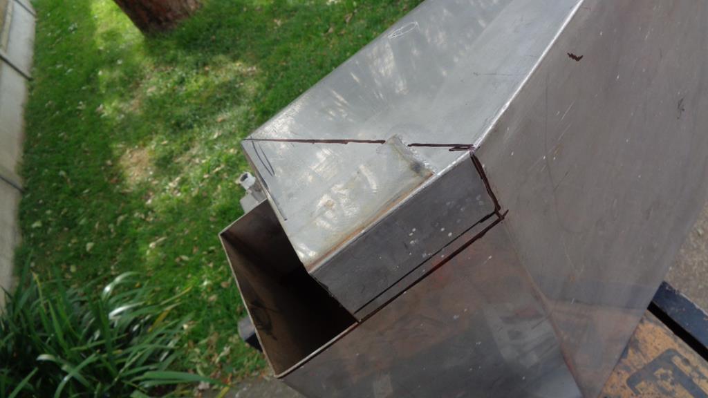
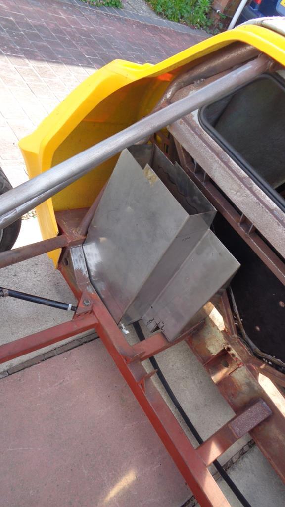
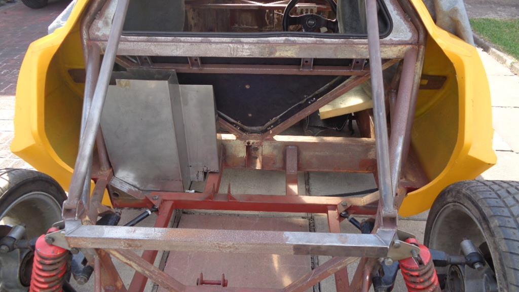
Is there room for a matching tank on the other side? I have a 7 gallon tank in mine and on longer journeys it is a pain to have to fill up at the mega priced motorway services. The exhaust sweeps around behind the driver and takes quite a wide arc - which is good in one way because it means I can drop the alternator down close to the block on that side and bad as it will run close to any tank I manage to squeeze in that area - There is some room but I am not sure that having it anywhere near a red hot heating element is the way to go - I can wrap the exhaust and insulate the tank but its still going to be quite a toasty corner of the engine bay. The original cars had what I can best describe as saddle tanks out in those areas just in front of the rear wheels. 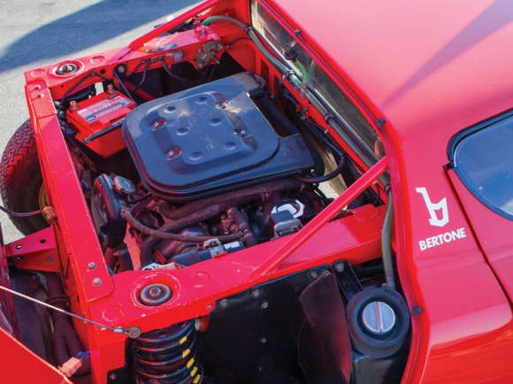 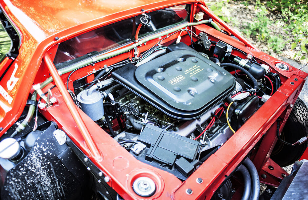 Its a nice place to have them as there is a lot of unused room there - However I guess for safety reasons due to the GF cars not having much structure to protect them the tanks are further inboard and located within the chassis and cage. The Ferrari lump has the diff central and behind the engine block which means the engine sits quite a bit further forward in the chassis ahead of the rear axle line (so no room for tanks behind the bulkhead)- In the reps with the diffs off to one side the drive shafts run on the engine block so the engine is a little further back in the chassis allowing extra room in front. The Alfa engine being taller and narrower 60 degree V has even more room in front and usually with the Alfa engine cars they sweep the exhaust under the engine as in the donor. The Honda is a low wide 90 degree engine - great for CofG but not for space fore and aft. In the Ferrari engine Litton they did place the tank over the side sill but I have lots of cage tubes there that prevents it. |
| |
Last Edit: May 26, 2020 5:40:07 GMT by Darkspeed
|
|
|
|
|
May 26, 2020 11:53:02 GMT
|
|
Ah yes, the typical problems of a big engine in a little car........I know it well!
|
| |
|
|
|
|
|
May 26, 2020 12:19:16 GMT
|
don't know what you mean....... 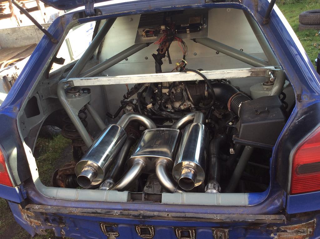 |
| |
|
|
|
|
|
May 26, 2020 12:21:10 GMT
|
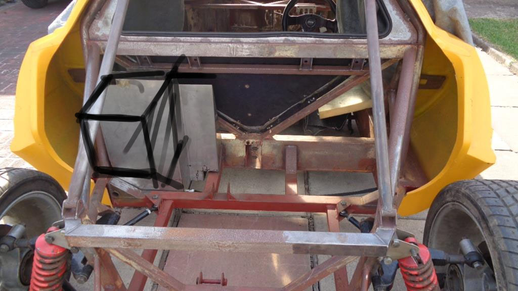 is there any room to extend the tank out over the top of the gearbox? [dodging the cage better than shown in my sketch] |
| |
Last Edit: May 26, 2020 12:27:27 GMT by legend
|
|
Darkspeed
Club Retro Rides Member
Posts: 4,845
Club RR Member Number: 39
|
|
May 26, 2020 13:09:45 GMT
|
don't know what you mean....... Oh the Luxury of having the space you have there is there any room to extend the tank out over the top of the gearbox? [dodging the cage better than shown in my sketch] Maybe - but the chassis rail pinches in quite a bit and the other difficulty is actually getting the tank into where it sits - The original builder fell foul of getting a tank made to the dimensions of a space without considering if the way into that space was big enough to get the tank through. - I had to cut off large parts of the tank to get it to fit where it was "designed" to. Plus - I would really want to keep all the masses as low as possible. I will get that tank in as I know I have room for it and then once I have everything else I need to get in sorted I will have a closer look - probably after actually running it - may be one of those trying to solve a problem that isn't there scenario's. My Ducati had a 120 mile range tank and that was never an issue for me. |
| |
|
|
|
|
|
May 26, 2020 13:45:10 GMT
|
|
Really enjoying watching the progress....and admiring the skill!
|
| |
|
|