|
|
|
Jun 20, 2015 13:09:54 GMT
|
So after alot of faffing about and measuring and faffing and measuring and faffing and measuring........you get the picture, well here they are: The front suspension from the front, note that the black dot is the Roll Centre Height, which is very low. 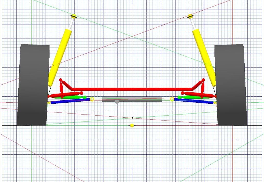 And from above, note the angle of the steering arms, this i only noticed when i started measuring stuff, this will have consequences later! 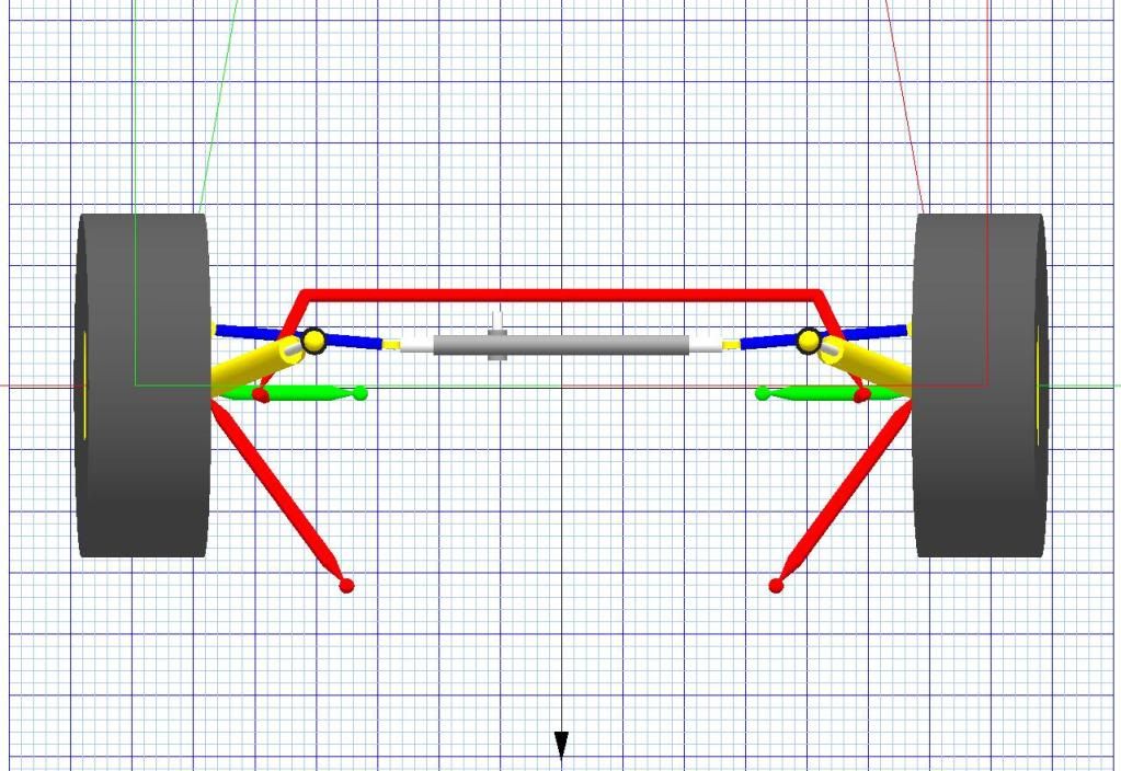 And finally the rear suspension, i have shown it like this otherwise it looks a bit boring! 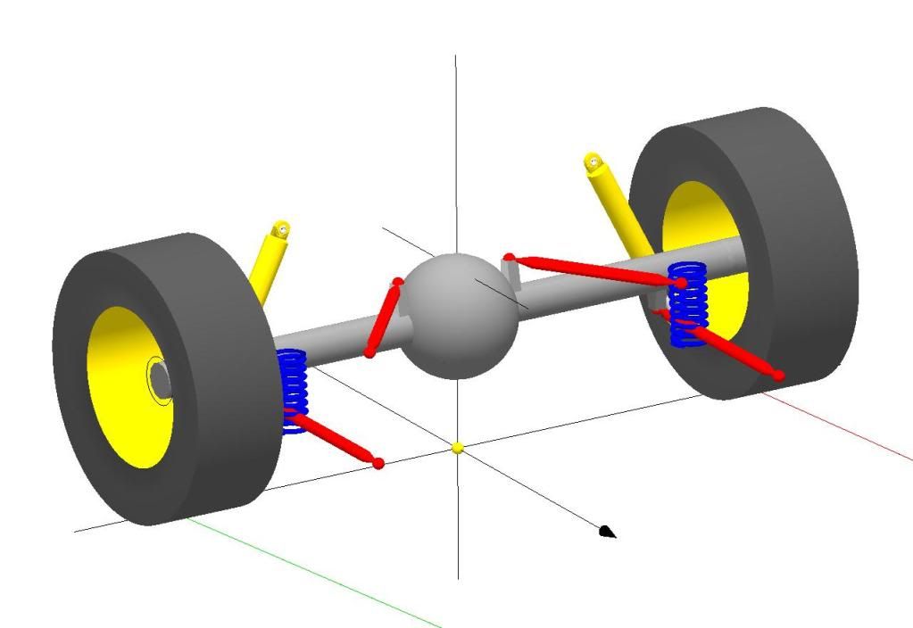 Phew! Thats only taken a while and made my head hurt. I shall be away to do some calculations and see what falls out........................ |
| |
|
|
|
|
|
|
|
Jun 20, 2015 13:11:17 GMT
|
o round the evening off some more pretty pictures: Bump steer in degrees against suspension travel 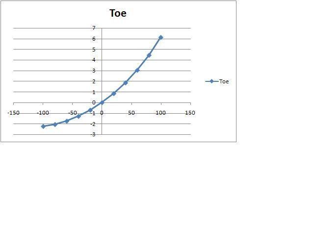 Roll Centre Height in mm against suspension travel 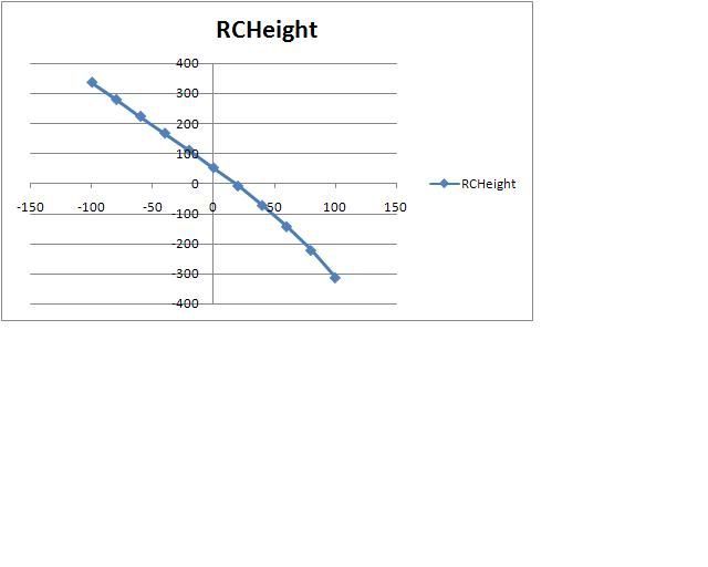 Both the above have a marked effect on the handling of an Avenger or Sunbeam. The RCH is poor due to the angles the suspension arms make so i need to change what i can in the program and see if i can ge the RCH and RCH Offset to be a bit more stable and that should improve the front end. The bump steer is also very poor, pressing a button on the programme to minimise it places the rack in a new position which is to the rear. Not lowering as most after market kits seem to do...................... Improvements will cause flat lines, i hope!!!! Next times thrilling instalment will show the improvements - on paper - and then see what that translates to on the car. |
| |
|
|
|
|
|
Jun 20, 2015 13:12:59 GMT
|
|
I have just 'run the figures' and as you have both found before the rack does move down as well as back. I think i missed the downward movement before.
I think a combination of moving the rack and the inner TCA up will achieve both minimal Bump Steer and what i am aiming for with the Roll Centre Height. Currently the RCH is not well controlled but moving it up not only has the benefit of being higher but also better controlled.
There is no way that an Avenger/Sunbeam can achieve a flat or reverse inclined roll axis due to the fixed RCH with our rear suspension. I am aiming for the front to be at least half that of the rear.
I also read an interesting article about the rear linkage like we have on American race cars, where they found going as soft as possible works very well due to something i cant now remember! Time to look it up again.........
|
| |
|
|
|
|
|
Jun 20, 2015 13:13:55 GMT
|
So as Tim and Alan have found, moving the steering rack back and down relative to the TCA improves bump steer which is quite large. If the rack is moved rearward by 25mm and down by 25mm we get the result shown below: 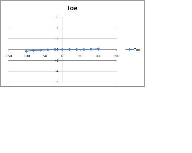 Bump steer is virtually eliminated. Connecting the rack to the coloumn will be hard with it moving that far though. |
| |
|
|
|
|
|
Jun 20, 2015 13:14:40 GMT
|
|
I ran a quick calc yesterday where I move the inner TCA point up by 10mm to help with the rack re-position and the outer TCA down by 30mm by lowering the balljoint mount. The rack then only goes down by 15mm.
This resulted in the RCH - in Roll - being much better controlled. It moved vertically by less and the offset stayed within the wheel track. Also the roll axis from 45 degrees to 135 degrees which is big improvement and of course the theory is fine but the proof of the pudding is in the ragging. My aim is to make it as easy to drive as I can so I can be on top of it quick as poss as soon as the timing light breaks.
I have a spare cross member but need to give some thought to the ball joint spacer in terms of the bolt/studs etc.
|
| |
|
|
|
|
|
Jun 20, 2015 13:16:59 GMT
|
So here are some photos of the cross member tht i have made to allow me to alter the rack hight and the inner TCA position as necessary. It also moves the engine down and back slightly. 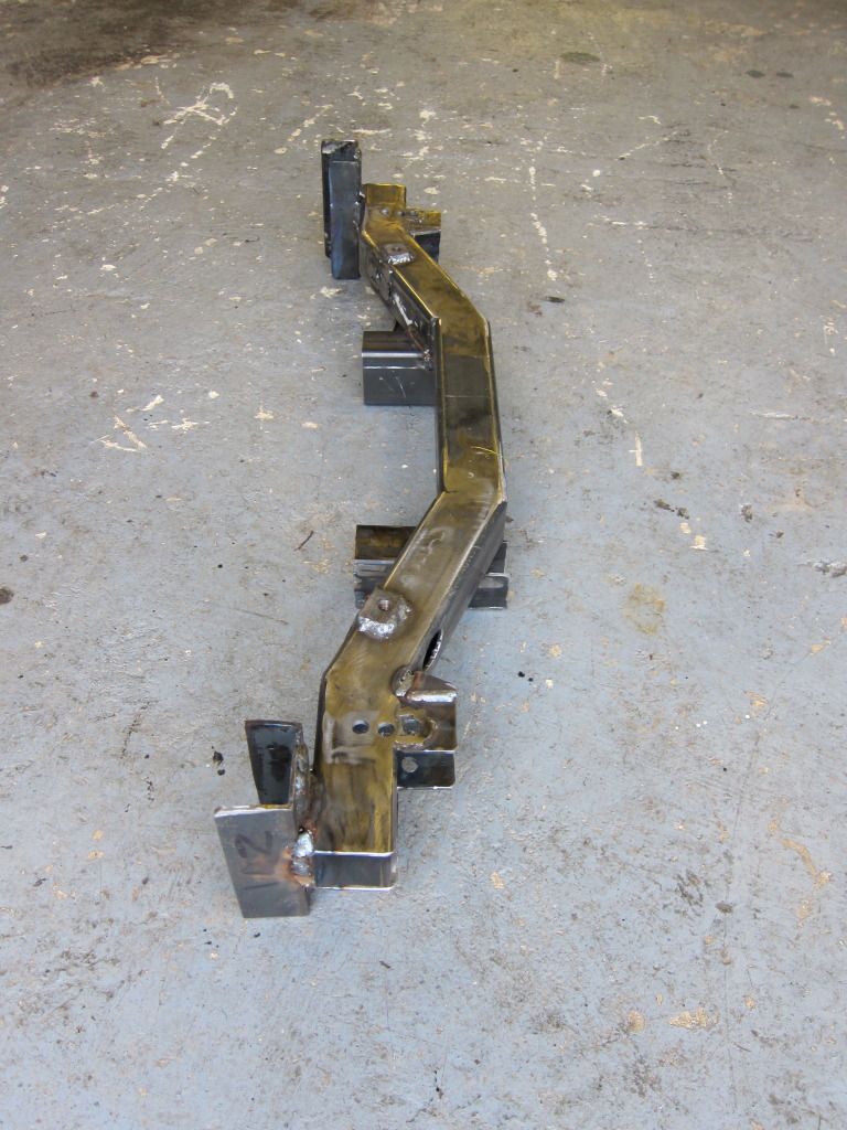 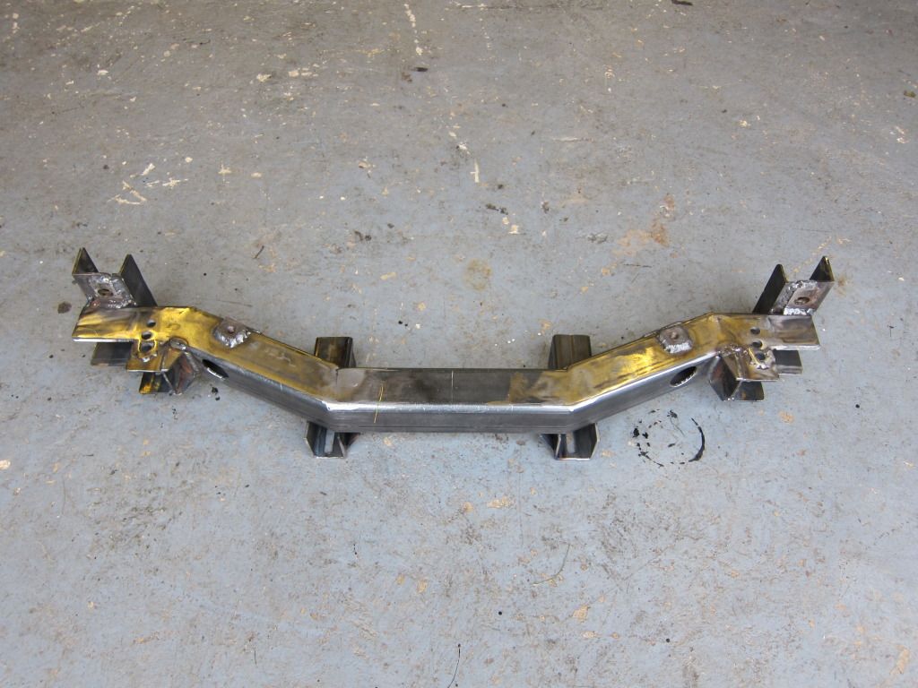 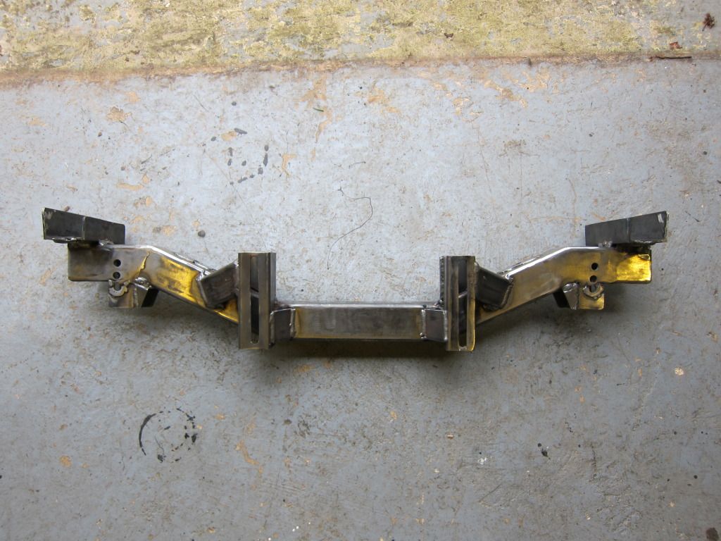 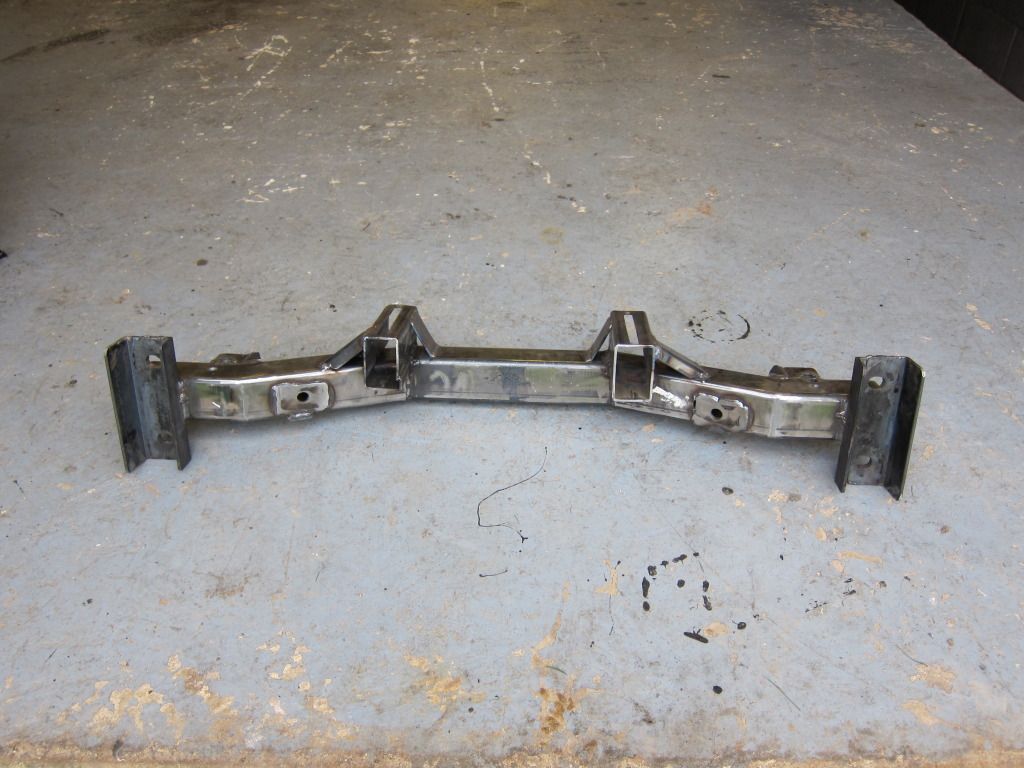 As soon as i am home again i can paint it, fit it and fit the rest of the engine gubbins and mount the gearbox. Then if the correct radiator ever turns up - hint - i can get it running!! (This refers to buying an Alloy radiator off of Mal Stuart - he kept sending the wrong type) |
| |
|
|
|
|
|
Jun 20, 2015 13:17:33 GMT
|
|
he box section wall thickness is actually as thin as I could get, it looks much bigger in the photos, although the U section on the chassis mount is thick as that's what was under the bench and is indeed Land Rover derived!
The front threaded plate is for an additional bar that runs forward to to the BRB mount to triangulate the front of the chassis.
It maybe slightly over engineered but I was trying to think about the forces introduced by using wider proper racing tyres rather than road tyres and what that might do.
The engine has moved down a further 15mm, it was already down by approx 20mm and has gone back another 10mm.
More progress at least.
|
| |
|
|
|
|
|
Jun 20, 2015 13:18:02 GMT
|
|
The front BRB mounts are tied together across the car using 43mm CDS, roll cage tube, I did this previously as an upgrade to the box section that was there to mount a sump guard. As it happens I retained the sump guard mounts just in case!
The engine mount is fully captive, it uses leaf spring bushes bolted through a square 'cup' sat on the crossmember. The only reason the cup is not welded to the crossmember is to allow fiddle space when fitted/removing the engine.
I have a test day in a couple of weeks...........
|
| |
|
|
|
|
|
Jun 20, 2015 13:20:59 GMT
|
So engine in and Gearbox in: 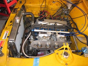 A photo of the type of captive engine mounts i use: 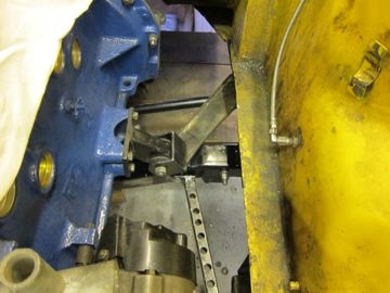 A Lotus type ARB has been fitted now too, i use poly type bushes - thanks Mark - but as you can see the alloy spacer needs some relieving to allow the retaining strap to fit: 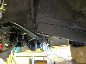 Then i made a bump steer gauge and checked it all out: 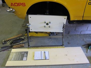 The gauge shows there is still some but i can't be arsed to fiddle around now. I have set it to the minimum and will have a proper play later in the year. I then set up the front camber but run out of adjustment at 1.5 negative. I was using 2 negative before so we will have to see whether that is adequate. If not it will just mean i accelarate the construction of alternative bottom arms with the adjustment at the outer end rather than at the cross member end like it is now which is a bit of a pain. I also got the engine running, well it started first turn of the starter. The tappets are loud enough to make my ears ring which might be ok ok as all the checks are good, i am not used to solid rocker gear with out springs etc. Rolling road once i sort the steering link out, well not me really its being sorted by a steering engineering firm as i type. So, the car is in real danger of being back out inside a year! |
| |
|
|
|
|
|
Jun 20, 2015 13:23:06 GMT
|
|
Its been a bit quiet so i thought i might write some drivel.
I finally sold my Mag Minilites from BDU 222Y to a guy with an RS1800, these had originally been purchased from me by a person who agreed a price after a negotiation (and included the works manifold and sump guard), the person even went so far as to obtain my details to transfer the money. Then nothing, not even a reply to my emails and PM's on this forum.......
So the Lotus Works manifold went on saturday and a spare rally head and cams i had, i fully expect to see them on an Avenger Estate some time soon!!
Although pictures of the engine are shown above it has a problem, in so much that it makes a really loud tapping when running like a demented elf and a hammer. We are not sure what the problem is but hope to resolve it soon, really soon is my hope. No point having a racing car that don't race. Or can't be driven........
Next job once the engine runs properly? Make 4 old Avenger doors the lightest Avenger doors - ever!
NB: this was the start of a long court battle that ultimately was won. I had given the engine parts to Mal Stuart to put together but as can be seen in this post things were not going to turn out well at all......
|
| |
|
|
|
|
|
|
|
Jun 20, 2015 13:26:18 GMT
|
April 2012 now:: Whilst i await the engine investigation i decided to crack on with the doors, as it does not stop the car being driven, if it gets going that is!! So up to the garage attic/storage room/sauna and lower a good passenger door down. After stripping all the normal gubbins off i was left with this: 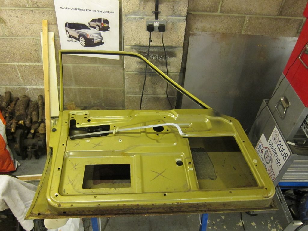 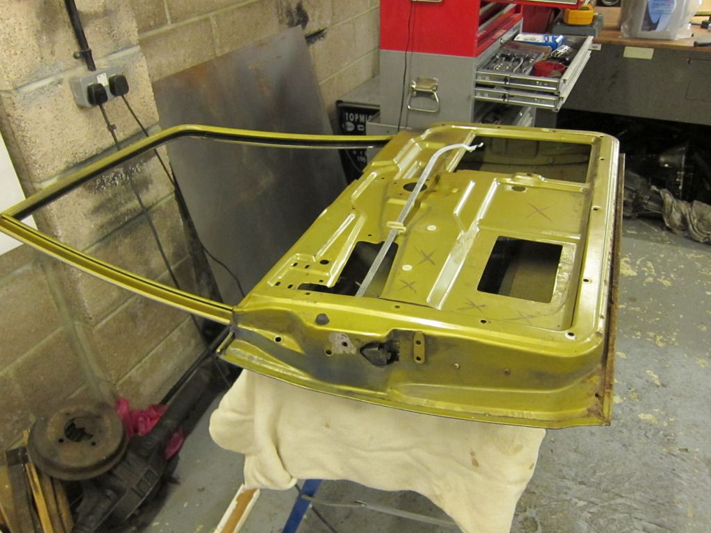 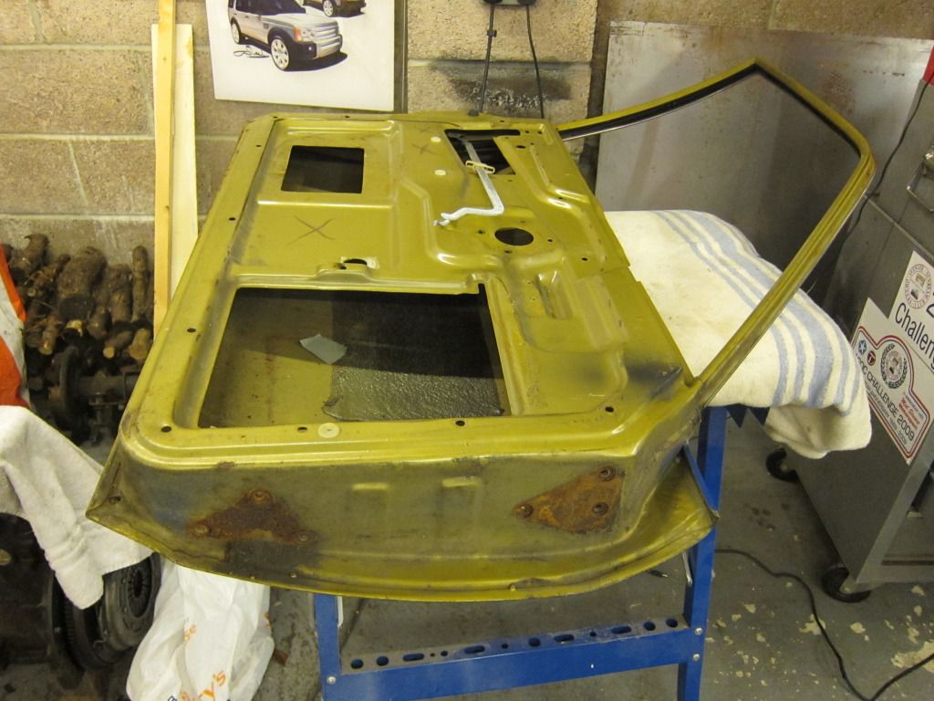 Then after a bit of anger management i ended up with this: 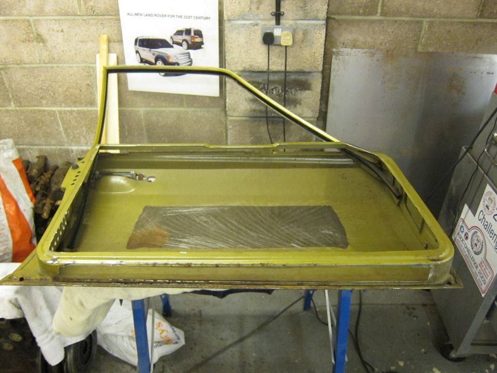 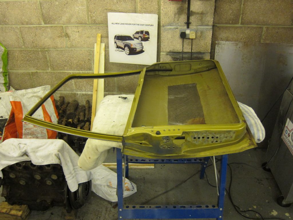 Note the bottom of the door is also cut away, i think i have taken as much as i can without the door becoming too flimsy, its only the front passenger door and i don't carry passengers...... With a bit of alloy sheet to cover the big hole and a bit of wire to open the door - like the early Mini doors - it should be all good? I mean what can possibly go wrong? |
| |
|
|
|
|
|
Jun 20, 2015 13:26:36 GMT
|
|
The drill holes are just extra lightening without getting to wobbly! On the rear doors i have cut even more away as they lend them selves to it. The rear doors i do not intend to panel in at all, i will see if they flap too much and change if necessary :-) The front doors will have panels to add some stiffness and for safety.
The poly windows will fill the gap left without the 1/4 light so will in effect look like a mini Sunbeam door. I shall do that front and rear. It might look a little odd but i hope for the better!
The front doors need some small repairs along the rear edge corner so that it is my next job, gulp. I am not very confident with body work!!!!!!
|
| |
|
|
|
|
|
Jun 20, 2015 13:27:38 GMT
|
|
great pictures on the suspension geometry. this was what i meant in the thread in general discussion (the F1 inspired hot rod) it was lowered so much the roll centre was subterranean. the advantage of low COG completely outweighed by cataclysmic roll centre
|
| |
|
|
|
|
|
Jun 20, 2015 13:28:06 GMT
|
The rear window is now Poly as well! The regs state that no metal is to be cut or modified from the shell inside the wheel base, so i can cut the boot floor out but not fit 4 axle links like an Escort. Which leaves just the bonnet and boot lid to be changed to something lighter. Fibreglass versions are available and are lighter but they are designed for rally cars and as such are good and strong but i think a bit more weight could out from them as well if i go that route. So each of the doors has a good helping of surface rust along the bottom but nothing that some good treatment will not cure. Except one door: 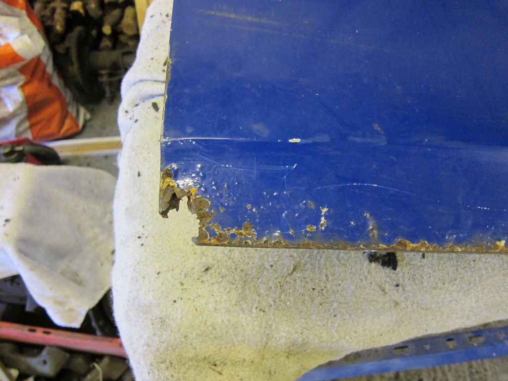 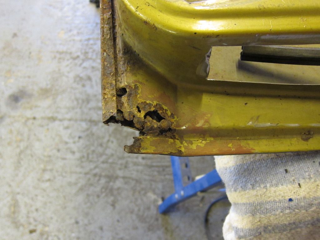 Not a large amount to deal with but something i have never done. I have done patches on chassis and floors but never where it might be seen!!!!! And its the drivers door. That is next weeks job. Engine still awaiting a resolution of its demented Elf fitment. (Which turned out to be the pistons hitting the head...........) |
| |
|
|
|
|
|
Jun 20, 2015 13:30:19 GMT
|
|
So, the engine went back to the engine assembler man yesterday, still fitted to the car to make diagnosis a little easier.
After some investigation work it was decided to to take the head off as the cause of the tapping could still not be found.
Imagine a knackered Ford Pinto tapping and you get a sense of the noise.
So off comes the head and suddenly the engine assembler looks and says 'Pistons are hitting the head'.
And in deed they are, just.
Seems the clearance of 0.75mm that he should have left was not and the piston just pings the head. There is no noise when turned over by hand or on the starter motor so i think the piston hits when it tips slightly on the exhaust stroke at TDC. It is solvable and seems not to have done any damage so its looking good again.
I am glad i did not ignore it! NB: The bloody idiot then, rather than removing the pistons and matching the clearance had a de-compression plate made which took the pistons well away from the head and the very detailed squish we had designed in.............
So the extra clearance is being sorted over the next 2 weeks and then i can, finally, get the engine on the rolling road and see what it does!
On a different tack, i have been offered an axle with a 5.1 diff, not a Ford Atlas but a genuine PTS one. I am sure it would be ideal on the Hills but not so sure about Sprints but maybe with the 5th gear i have that will be ok.
I have looked at the gearing calculator thing and a top speed of 110mph at 7500rpm with the 5.1 is possible which might be a bit short for Castle Coombe but its worth a try.....
No pictures of the pistons and head as i was not in the mood to take pictures.
|
| |
|
|
|
|
|
Jun 20, 2015 13:45:49 GMT
|
great pictures on the suspension geometry. this was what i meant in the thread in general discussion (the F1 inspired hot rod) it was lowered so much the roll centre was subterranean. the advantage of low COG completely outweighed by cataclysmic roll centre I have been playing with the set up again this year and will get it posted up here once i catch up with the 4 years worth of posts................. |
| |
|
|
|
|
|
Jun 22, 2015 14:43:06 GMT
|
So it happens that i have picked up my car now with an engine that does not let the pistons hit the head! But when taking it off the trailer the noise from the release bearing area was very loud so the gearbox needed to come put and see what was going on.... Upon taking the gearbox out i found the spigot bearing on the input shaft and to in the end of the crank. It was obvious that the spigot bearing had been spinning and this was the source of the noise. Also the spigot bearing appeared to have been only fitted to 1/3 of its length. Its now fitted deeper into the crank after i measured how far the input shaft would go in. I also found that the release bearing was a bit damaged: 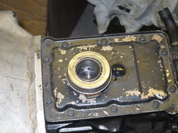 It can be seen that the bearing has collapsed a bit! That was due to this: 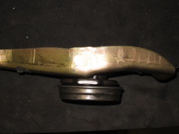 Due to using this clutch: 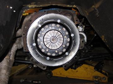 The clutch fingers are flat and further away from the release bearing than in a standard clutch and also they require a round nose thrust bearing. The photo above shows the standard Talbot release bearing on the arm but this does not give enough reach and the bearing falls off the end of the gearbox input shaft housing. So i needed to find a round faced release bearing that will fit over a Ford Type 9 input shaft (same as my Skip Brown Group 2 box as it happens) and has more reach. Mal was unable to help so i had a think and came up with the idea that it must be similar to an escort running this type of box and clutch. Burtons do a release bearing and extend carrier Et Voila: 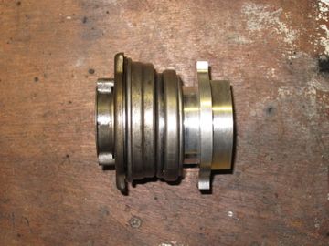 This is compared to the old release bearing and now on the arm: 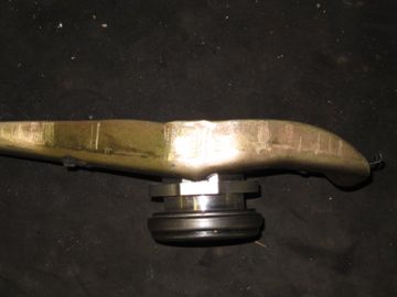 However, two problems remain, one is retaining the bearing onto the arm and the other is the arm angle and length. Retaining the bearing took some thought but wire lock and split pins came to the rescue. The arm length is due to the pivot being slightly different in the bell housing i am using, so out with the cutter and welder until i had this: 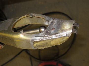 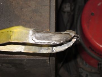 Which allows the tangs to sit central over the input shaft now: 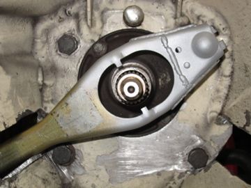 Then refitting the whole shebang gets this: 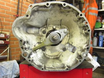 Just to refit the box now............ |
| |
|
|
|
|
|
Jun 22, 2015 14:45:57 GMT
|
|
So the Box is back in and the clutch is working correctly.
It is of note that the box has been in and out since the last update just to get the clutch arm angle and mushroom pivot length 'just right'!!!!
However, the las time the box came out the spigot bearing had again spun in the crank. This being spigot bearing number 2. It looked like the bearing had picked up on the input shaft of the crank, proabably due lack of clearance.
It seems the first one was dimensionaly incorrect on the outside diameter, hence it spun in the crank.
The second was dimensionaly challenged in its inside diameter - once fitted - as the box had been tight when going in.
The thrid spigot bearing was dimensionaly adequate it appears so far and the box slid in very easily.
It is interesting as the first two spigot bearings were of a similar material and machining. Infact the machining was a bit shoddy to be honest with grip marks on the outside surface.
The third, by contrast was very well machined. All three seemed to be machined from 'oilite' and all three had been submerged for over a week each.
So now i have to check the tuning software when i get back home so the rolling road goes smoothly.
Then i shall fit a passenger seat (need to get one first though) for the Saturday run out at the National and if i get time fit the 5.1 CWP and do an event - that will be a novelty.
|
| |
|
|
|
|
|
Jun 22, 2015 14:46:43 GMT
|
|
So,
I order the correct for year speedo cable from Speedy Spares, they send a late version, no problem they replace it with the correct onei.e. screws on at the speedo head.
I obtained it with a view to modify it much the same way as Ken did to fit the Type 9.
But i had a thunk. Any thing i do will be a bit of a bodge, hmmmm.
So what about something that hasa type 9 box and also a screw on head at the speedo end???
What about a Mk 2 Cortina with a type 9? Well as it happens yes and i now have one. Seems long enough compared to the old one too. just got get back and try it.
Not had a speedo for over 7 years, so will be a bit of a treat :-)
|
| |
|
|
|
|
|
|
|
|
Only just found this thread
WOW
|
| |
|
|
|
|


