|
|
|
|
|
More playing around with the fuelling to get a good start and a good idle. Starting is becoming ok, its a mix of technique and correct fuelling. As i don't have an Air Bypass/Cold Start Air valve to start i need to start with a shut throttle and then as it catches open the throttle slightly to allow it to run. That seems to work when the starter is not playing up!!!! I have tuned the idle by ear by adjusting fuel until the idle is at its peak which has worked well. Any more tuning will have to wait as my trusty old Innovate LC-1 wide band controller has died and keeps crashing so i have got a new version the MTX-L which comes with a gauge that is also the controller. The old LC-1 was a bit of a lump so this will make packaging easier and look a bit cooler too 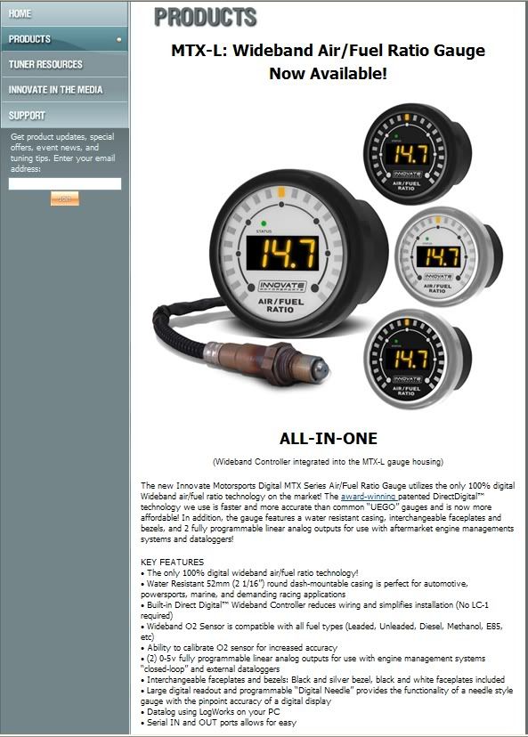 I do have a small problem with just off idle which i thought was the progression holes but they are now blocked up and its still there, i need to tune properly and will i go i am sure. So, just the rear screen to fit - when it arrives - and then off to an MOT. |
| |
|
|
|
|
|
|
|
Jun 19, 2015 10:08:21 GMT
|
I managed to get into the garage at last this afternoon for a few hours. I refitted the bottom pulley which had been away for a duplicate to be made for my new engine and then i started it up to check it still worked! It did  Then i tried a bit of the tuning software i had not used before, the auto tune function. With an O2 sensor fitted and an AFR look up table the software will adjust the fuelling requirements of the engine to match the AFR in the look up table. All engines like the same AFR for max power give or take a small bit - and its the small bit i will need to dial in on the rolling road. But i gave it a try on and around idle and it sat there adjusted the fuelling really well. Below is the screen showing the tuning at idle, in theory i can now drive about and the software will pull the fuelling to the AFR i have told it to achieve. Then finally i can get it on the rolling road to twek it for max power and fill in the bits on the table that are hard to get to on the road - i.e. flat out......... 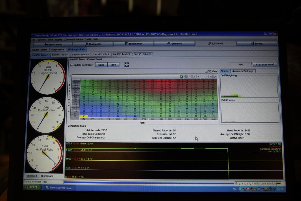 Here is the new O2 sensor controller and gauge. 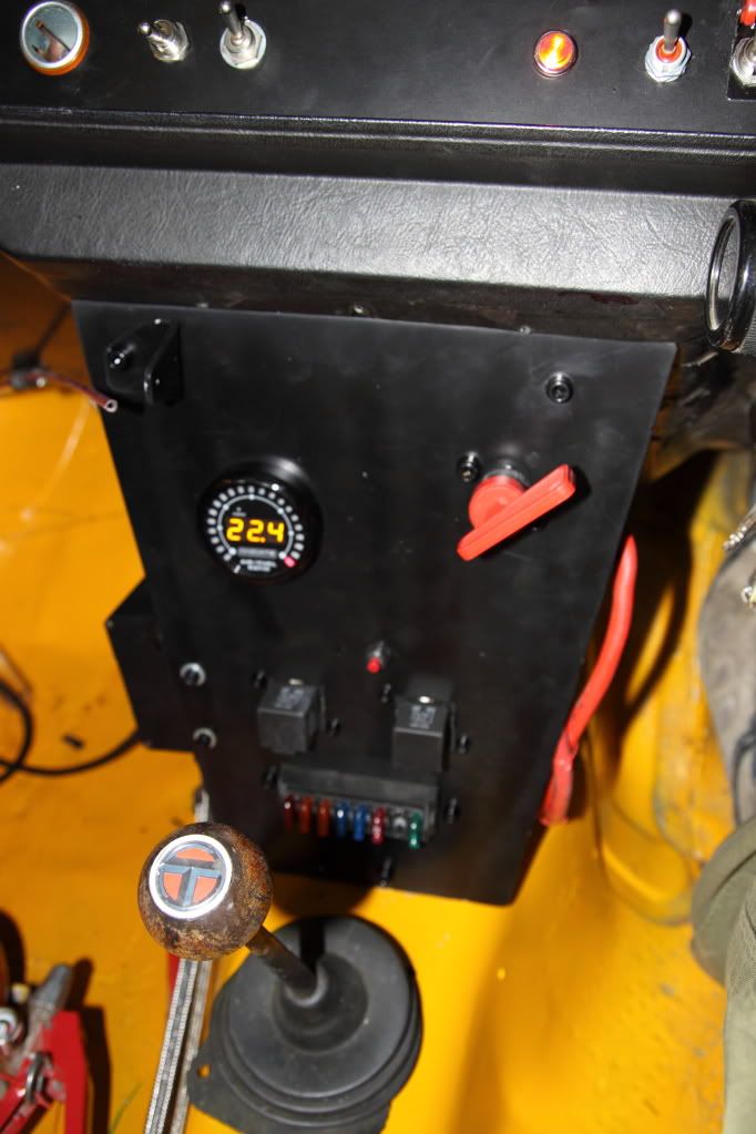 I also finally fitted the rear perspex screen. When i ordered it from Plastics4performance i asked for it to fit into a normal window rubber. It did not so had to go back but this time it fits: 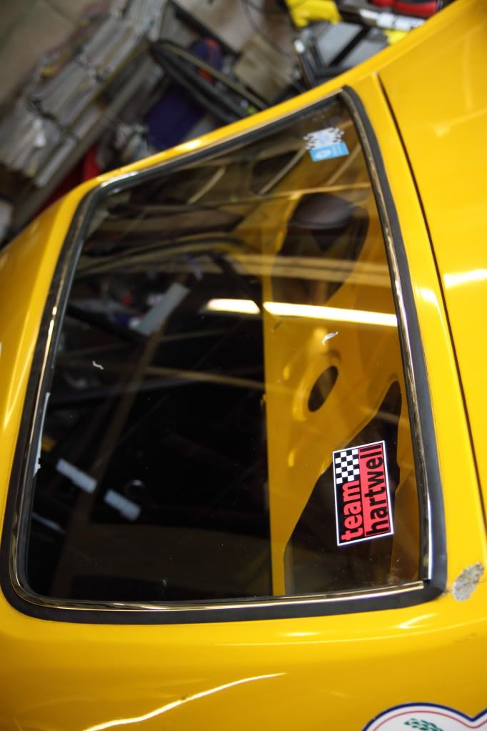 I also finished off fettling the gearbox shifter move ready for it to be welded. This is my 5 speed type 9 Tran X ready for a bit of welding - if i can find any one around here who can do it that is!! Then i can fit the box and see what it sounds like, i mean, see what it goes like: 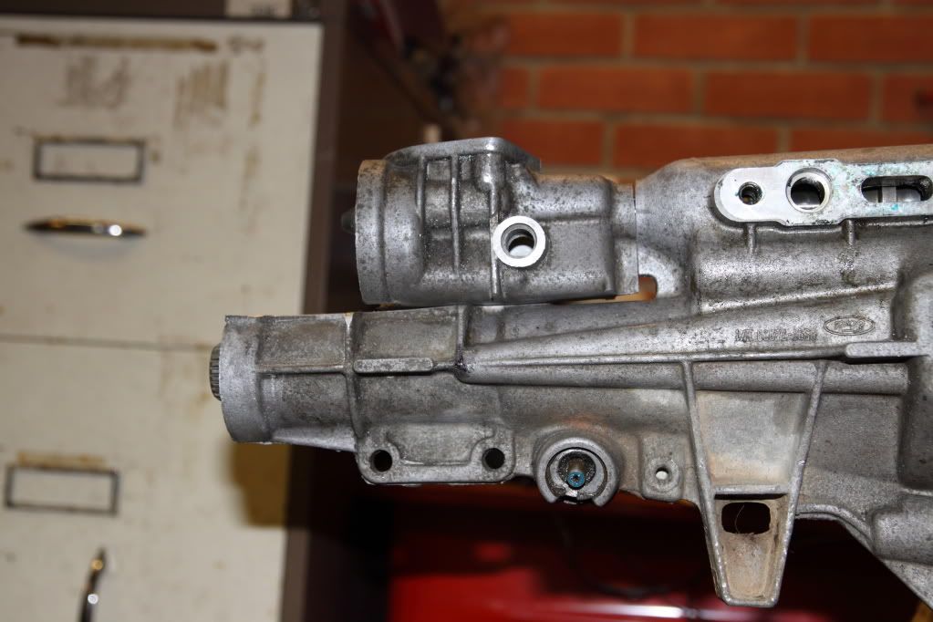 And a shot of the Lotus at Combe: 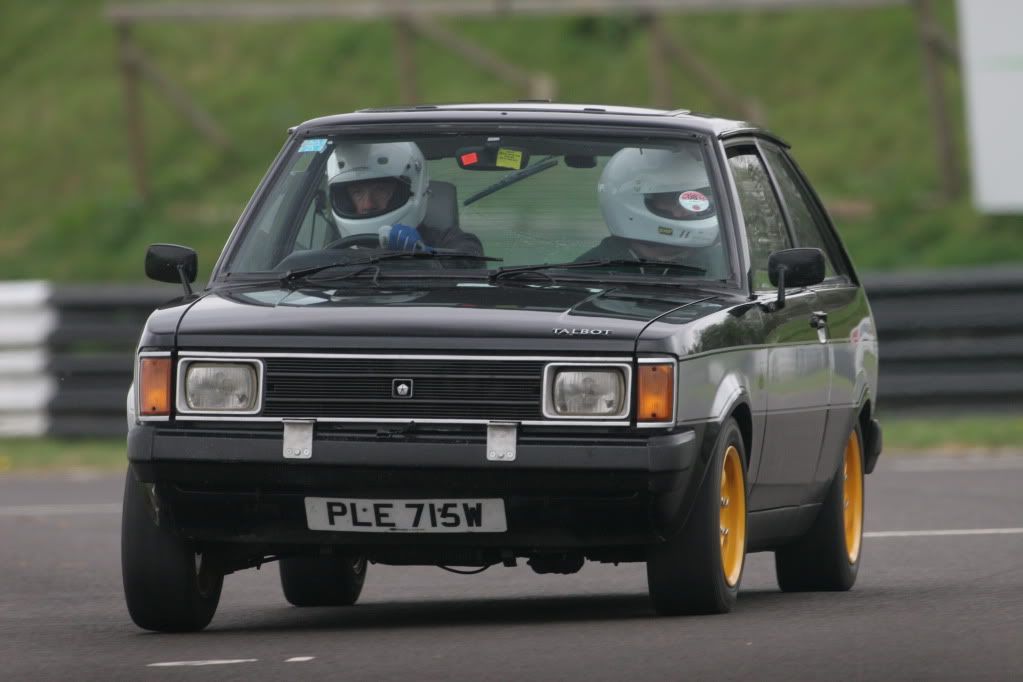 |
| |
|
|
|
|
|
Jun 19, 2015 10:09:15 GMT
|
|
The top mounts i purchased second hand but they are the ones supplied by Rally Design. They are marked TAP (i seem to remember and can be bought direct from them i guess) There is a 'top hat' that acts as spacer to ensure the strut top fits into the rose joint. My inserts are Bilstiens.
Front springs are 10" length - although with adjustable spring platforms it does not matter much! And are 225lb" in rate by memory. Rears are 9" 240lb".
The 240 rear springs are ok on a circuit in the dry just but every where else they need to be softer as the car is getting lighter on the rear end. Fronts are spot on. Damper rates are tarmac rates and maybe could do with some extra rebound. Of course this may all change as i am about to change to stickier tyres!!! I also run a rear anti roll bar - sometimes.
A hillclimb car seems to like to be a bit softer than a sprint/circuit car. It seems to me that sprints, circuits and tarmac events like the same settings on my car at least!
|
| |
|
|
|
|
|
Jun 19, 2015 10:16:03 GMT
|
At home for a fw days so to cheer my self up and get the car ready for its MOT i did some bits and bobs: B Post mounting for cage: 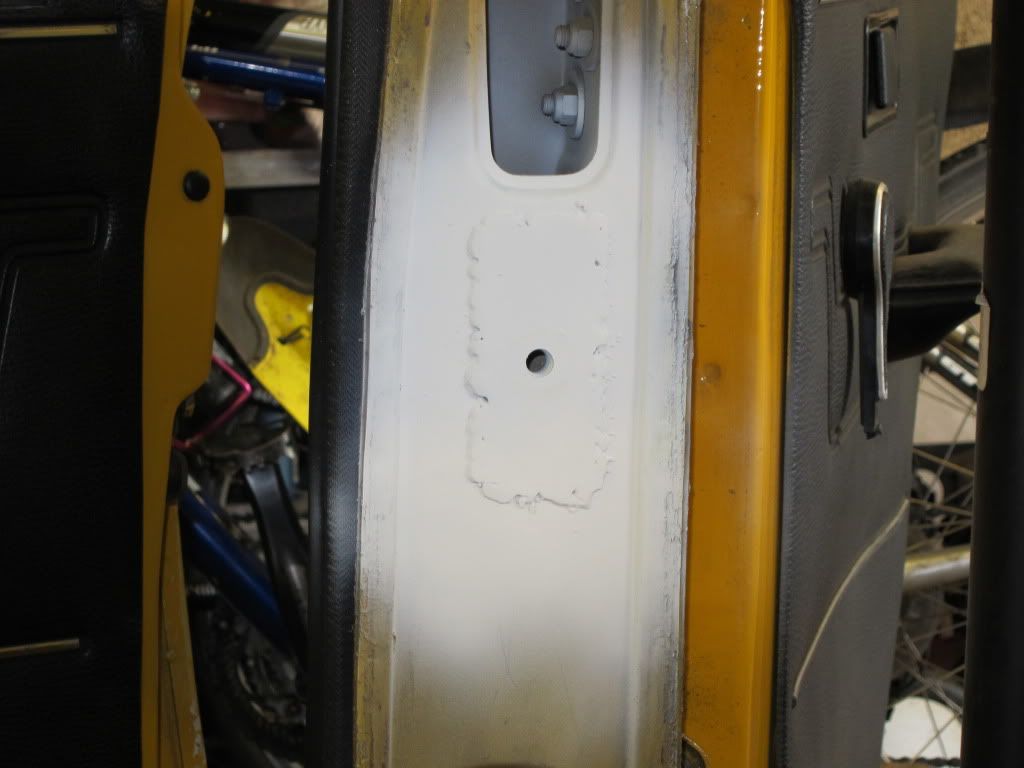 Fitted up: 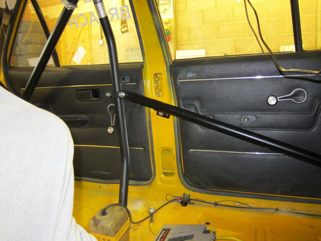 Made and fitted new strut brace to be a bit lighter. The cross bar is stainless but will change to aluminium in time: 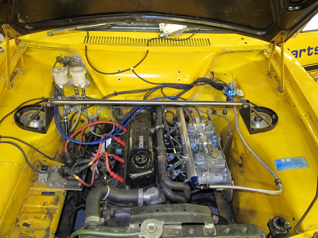 I then started tuning again just to get the car turned around but ran out of fuel!!!! |
| |
|
|
|
|
|
Jun 19, 2015 10:23:39 GMT
|
So the car is now MOT'd and i have completed a bit of road tuning and its pretty good. But i am not happy about the front suspension. The new top mounts have pushed the strut top mount down by approx 20mm which has caused the car to sit up at the front. To get this back i could just lower the spring bottoms but this will result in the damper almost being on the bump stop. Therefore, the top mount needs to be raised to allow the damper to have a bit more stroke. I have seen a very smart aluminium top mount on some Sunbeams that raises the top mount (allowing the car to go lower) which is a single machined piece of Alloy. Although very tidy it does have two draw backs; it restricts the amount of camber and castor that can be set as it restricts the strut moving (not a big problem i suspect) and its cost. So, deciding that i can do the same, for less and accepting it will not look as cool i came up with this: 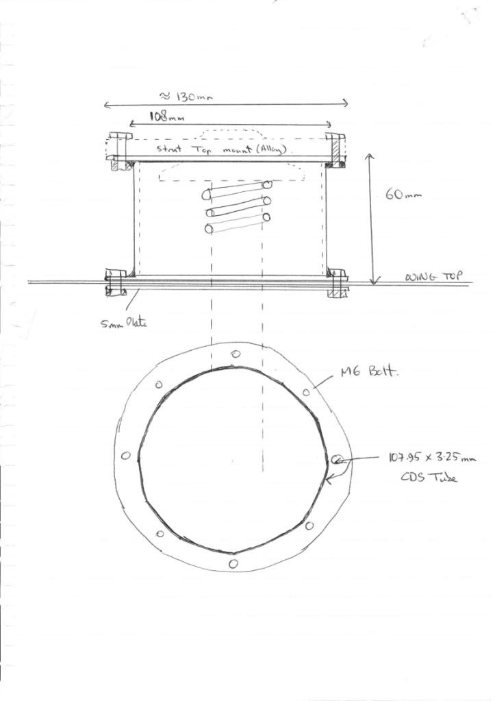 I know my drawing is a bit dodgy. Essentially its a piece of 107.95mm x 3.25mm CDS tube with a mounting ring welded on at each end. Almost as light as Alloy once the drill has been at it, although not as elegant. The Strut alloy, rose jointed top mount bolts to the top of the new tower using 6 rather than the normal 3 bolts. The bottom ring then bolts through the wing top onto a ring where the original mount would sit using again 6 bolts. This also means that taking the strut out is bit more of a faff as the top mount has to be seperated from the strut first. But the front springs are run under very little preload so its not difficult just a faff. So apart from the flaws i have mentioned can anyone see any others? |
| |
|
|
|
|
|
Jun 19, 2015 10:43:52 GMT
|
|
Just had a thought.
If i cut down the radius of the existing Alloy top mount then it would fit through the wing top and could be mounted on the under side of the top of the 'strut tower'. The tube would have a circular plate welded on it with a hole in the centre to allow the top mount to fit under much like it does now but slightly smaller in diameter!
Which makes it now a Mk2 idea ;D
|
| |
|
|
|
|
|
Jun 19, 2015 10:44:15 GMT
|
|
Tim & James,
With a quick measure 65mm is the approxiamte maximum i could raise the strut top to until it became an interference fit with the bonnet.
I could, as Tim suggested, just mount the strut top on the upper side of the wing. That would give me a bit more bump travel and possibly get the car back down to its former height.
However, as ever i want a bit more, so with properly(!) engineering the extended height mount it will give me more options with the front suspension.
It will create more bump space
It will allow a slight raising of the roll centre just by having the strut top at a higher level
It will allow the body to be substantialy lowered to lower CofG
It will introduce a small number of problems that i will need to surmount, for example i will need to re set the front TCA's so they point back up hill towards the centre of the car which may be a problem without spacing the wheels out.
But it will, potentially, be able to give the front end a much better handling feel and unltimately a higher cornering ability. As long as i do it correctly........
|
| |
|
|
|
|
|
Jun 19, 2015 10:44:48 GMT
|
|
I can tell that!
One of the problems i had before puting the solid top mounts on was that i have very pronounced understeer on entry on mid corner and then turing to oversteer very rapidly. I want to try and eliminate that by getting the geometry correct. With the solid top mounts its made matters a bit worse as i have no bump travel and the car is higher than it was on the front.
Its not a problem i ever ran into whilst rallying as the ride heights were just never as low. Its a fundemental problem with using a Mac Strut front end that in lowering the car beyond a certain point the geometery goes mad and negates the lower c of g. BUT if the geometry is brought back then all is sweetness and light again. It just means a bit of fabrications.
I have started drawing it out and the effort will be worth it i am convinced :-)
|
| |
|
|
|
|
|
Jun 19, 2015 10:45:22 GMT
|
|
I can tell that!
One of the problems i had before puting the solid top mounts on was that i have very pronounced understeer on entry on mid corner and then turing to oversteer very rapidly. I want to try and eliminate that by getting the geometry correct. With the solid top mounts its made matters a bit worse as i have no bump travel and the car is higher than it was on the front.
Its not a problem i ever ran into whilst rallying as the ride heights were just never as low. Its a fundemental problem with using a Mac Strut front end that in lowering the car beyond a certain point the geometery goes mad and negates the lower c of g. BUT if the geometry is brought back then all is sweetness and light again. It just means a bit of fabrications.
I have started drawing it out and the effort will be worth it i am convinced :-)
|
| |
|
|
|
|
|
Jun 19, 2015 10:57:11 GMT
|
Since the small problem i had with PLE i have sort off lost my car Mojo. However a weekend away with the wife, a garage clear out of all the old Bowler Tomcat stuff and buying some new tools is getting me back towards my Mojo  So i decided that i ought to try and mock up the suspension mods i am going to carry out. I have managed so far to create the bits that need to go together. Here are the component parts laid out on my spanking new work bench: 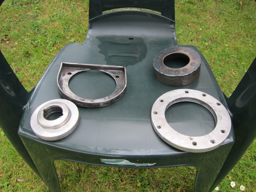 But can you tell how it all goes together? I think its like this: 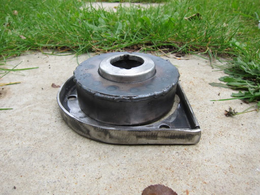 Note that the top mount for the strut is minus its Spherical Bearing, the old ones were a bit loose so i am replacing them. This is how it will all go together when on the car. You have to imagine the wing/strut top inbetween the lower alloy ring and the rest. 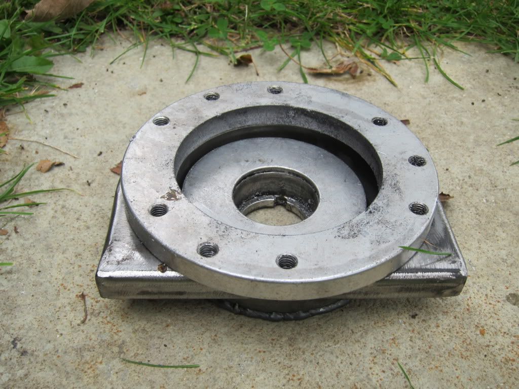 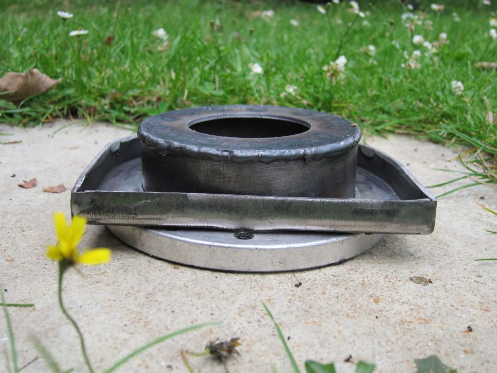 The extension piece has worked out at 30mm and gives a 35mm drop in suspension height. This is less than i mentioned before but one i have calculated to be the optimum.......... I mean designing suspension for a competition car, how hard can it be? |
| |
|
|
|
|
|
|
|
Jun 19, 2015 11:06:12 GMT
|
After enquiring of how to best fit spherical bearings to my axle i in the end bought a set of commercially available spherical bearing mountings already machined. I bought ones that had the closest outside diameter and large sherical joint that i could. Each of the two sizes i bought required material taking off to allow them to be pushed into the axle. First time i had used a lathe since being in school!!!!! But it all worked and soon had the housings ready to push into the axle. Although i actually pulled them in to the axle using the farms Special Tuning Tool 14. Here are the results, you can see that the mountings pulled into the diff housing bush holes are quite thin but are ok in reality. Bottom arm mounts: 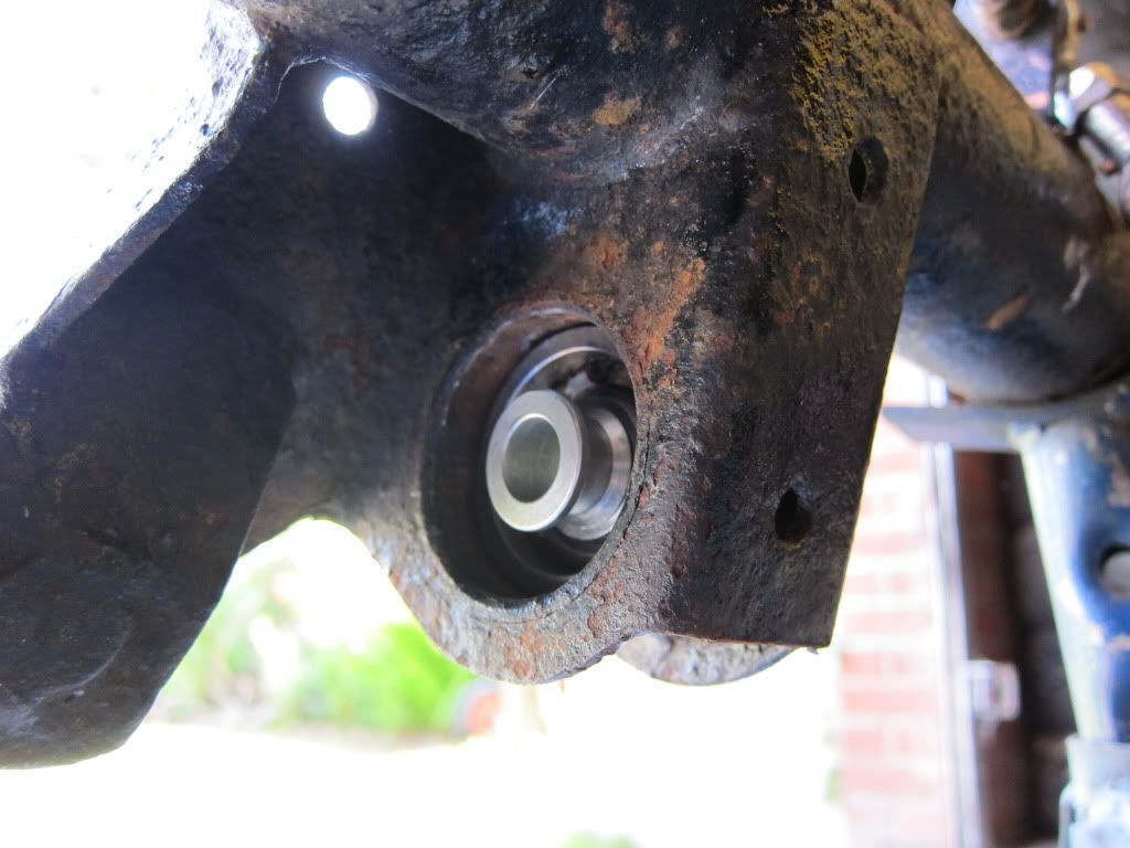 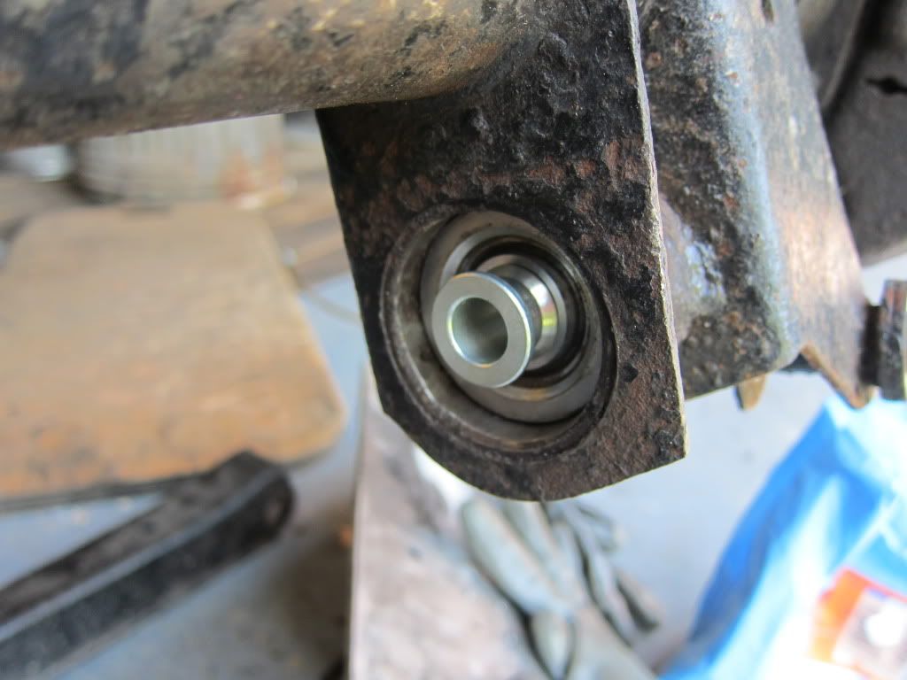 And top arm mounts: 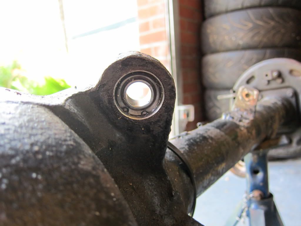 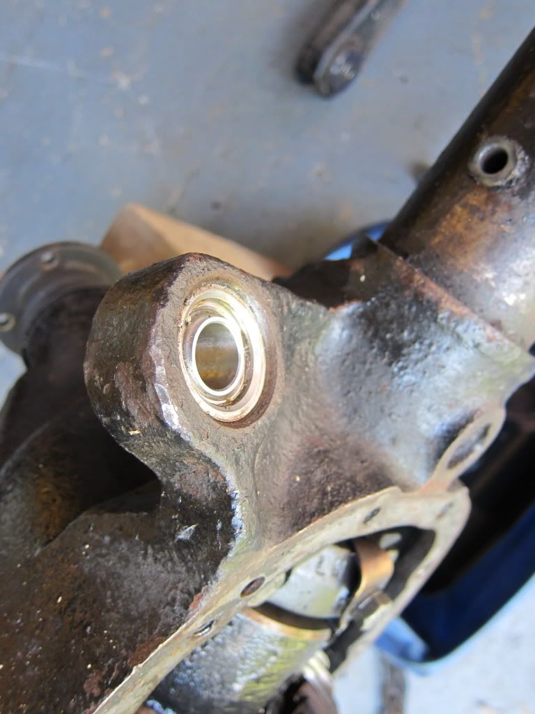 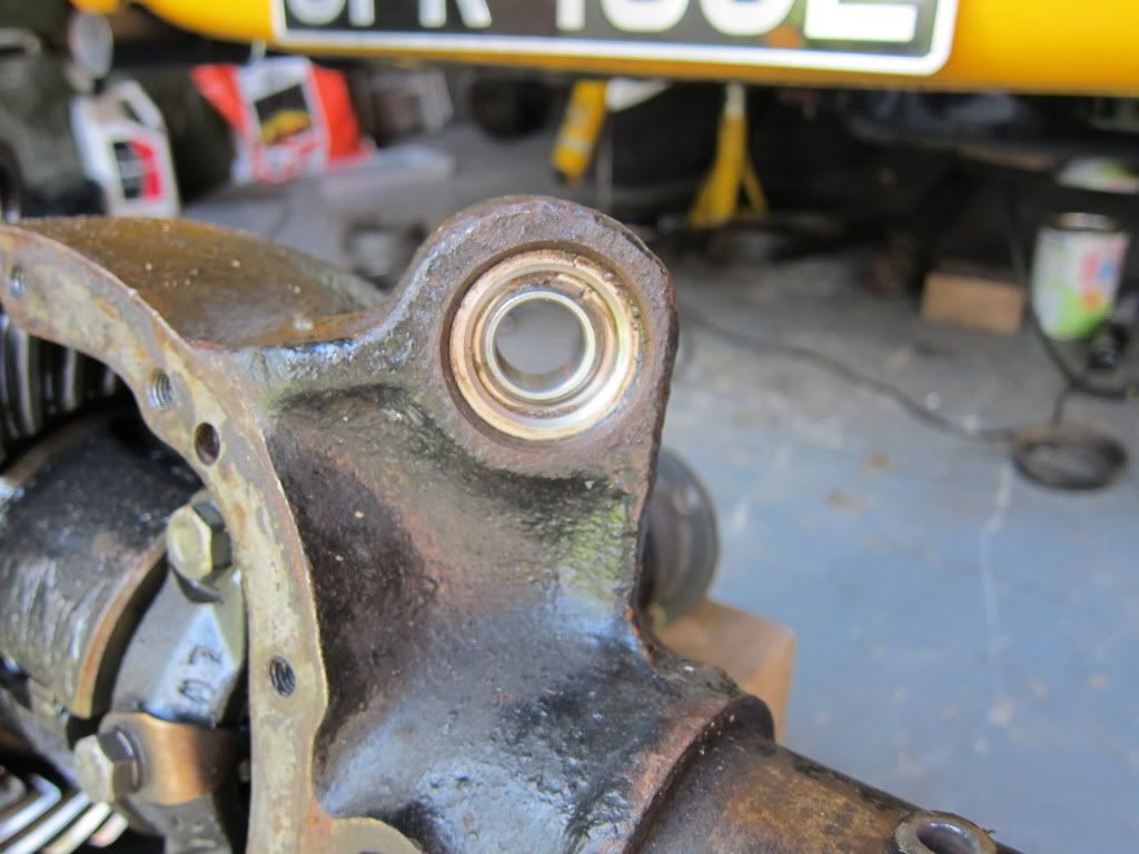 I will need to modify the bottom arms and the top arms to take rose joints at their front ends now but it is coming along nicely.  |
| |
|
|
|
|
|
Jun 19, 2015 11:07:43 GMT
|
|
Re-reading my pposts i may not have made the reason for moving the strut mounting up very clear. Its to get damper stroke and CoG down. I had run out of damper stroke when i fitted the solid top mounts which prompted this round of mods.......... Well not all of them but once it was in the car was in the air then i thought well why not
|
| |
|
|
|
|
|
Jun 19, 2015 11:12:59 GMT
|
|
Back Axle detail for 'DiY' rose jointing.
The bottom arm mounting i used a COM 12 Housing which has an o/d of 49mm which needs to be taken down to 44mm ish. We left a 0.5mm oversize to allow an easy pull in but sufficient grip to stay put with Loctite bearing lock.
Then in that is inserted a COM 10-12 Spherical bearing which has a 5/8'' hole rather than the normal 3/4'', then using 5/8" to 1/2" spacers the standard bolt fits.
For the upper arm mounting i used a COM 10 housing which has an o/d of 38.3mm which needs to be taken down to approx 32.6mm. Although the housing looks a bit thin by thin it has not got any where near the circlip grove depth and easily pulled in with no distortion. Again machined 0.5mm oversize and locked in with Loctite bearing tackle (or what ever was on the shelf at the farm).
Then a COM 10 sherical bearing was pulled in. This has a 5/8" hole so with 5/8" to 1/2" the standard bolt fits.
I used McGills Motorsport to supply.
The hardest bit of all this was learning how to use the lathe. I just could not get the surface that was being machined to look 'smooth'. It was straightforward to get everything true though.
|
| |
|
|
|
|
|
Jun 19, 2015 11:15:16 GMT
|
Finally got some time and finished off the front end, well i say finished, its all back together but i now need to do some measuring to see what i need to change to get the geometery that i want. The new suspension towers have now been fitted. As can be seen i have added a strut brace as well. I made the strut brace fitting out of some 8mm o/d cds tube. 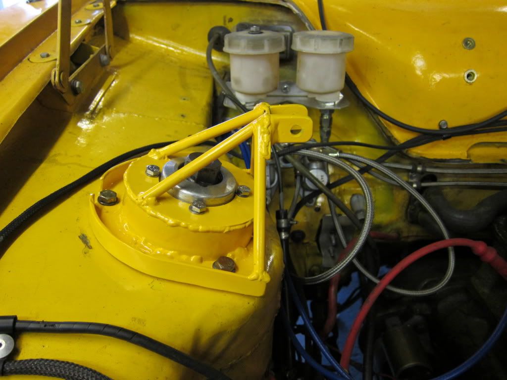 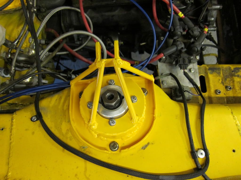 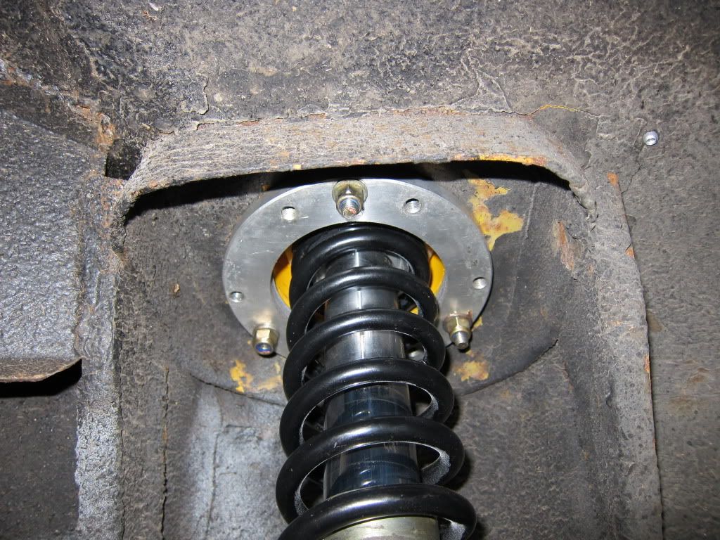 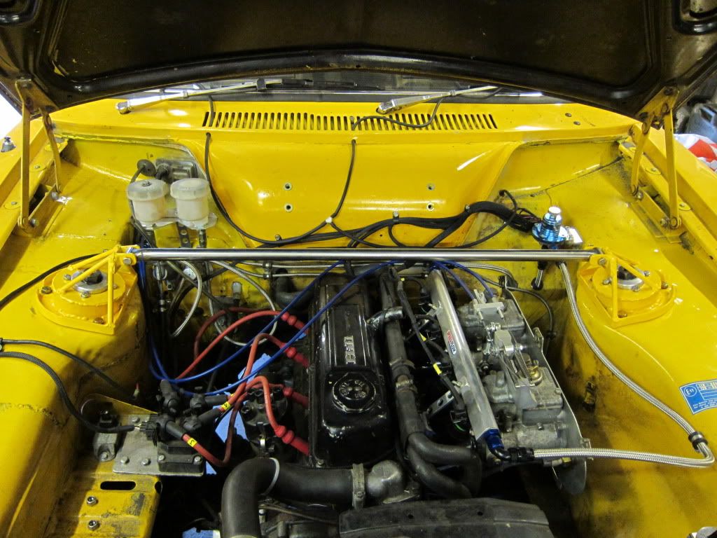 The back axle is back in as well but i am still modofying the rear arms and the spring arrangement so the spring seats are adjustable. However, work calls and i am some where sunny for a while but hopefully i will still have it ready for next season. |
| |
|
|
|
|
|
Jun 19, 2015 11:22:14 GMT
|
Any way some garage time resulted in me modifying the rear arms so the new wheels and tyres will fit: 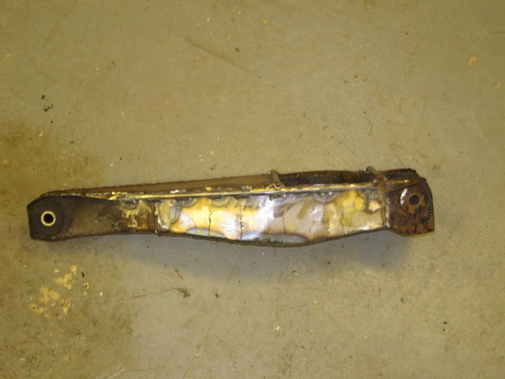 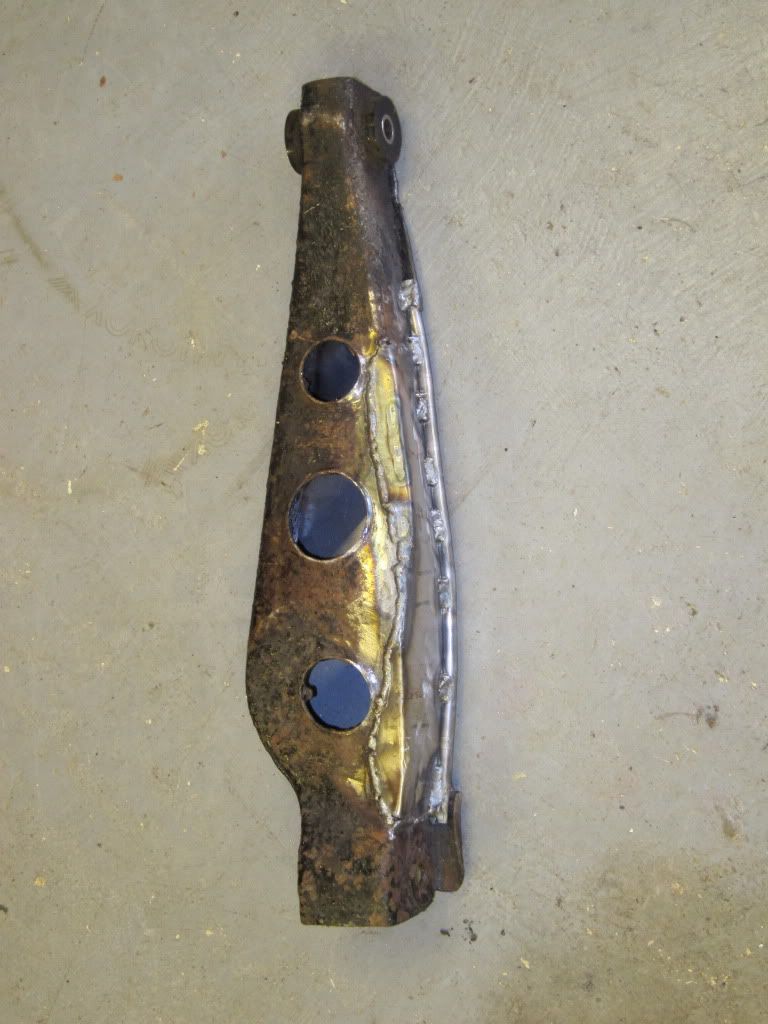 But that means the normal springs will not fit so i made these fit instead: 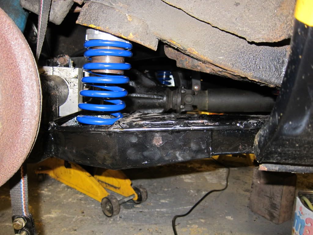 The car is now adjustable for ride height front and rear and sits at a crazy angle so i need to now level everything up!!!! I also fitted some tubular top arms and they give alot more room around the exhaust as can almost be seen in this 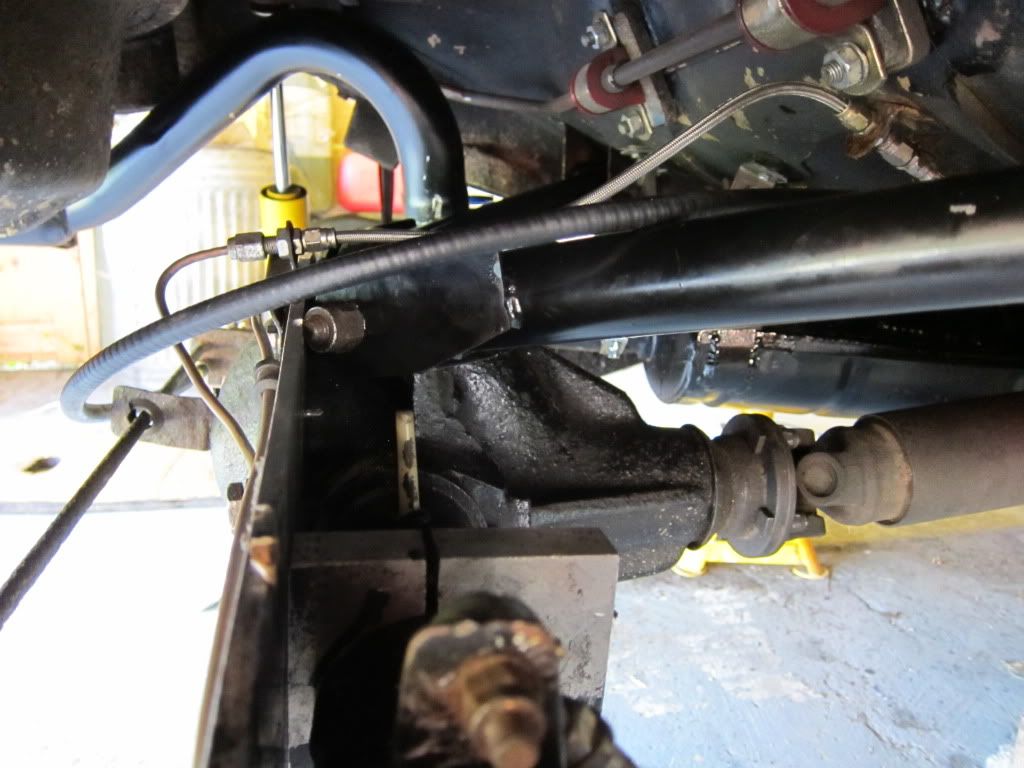 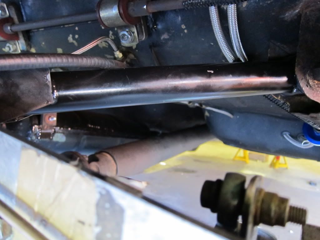 |
| |
|
|
|
|
|
Jun 19, 2015 12:12:27 GMT
|
|
what a fantastic build, top work!
|
| |
|
|
|
|
|
Jun 19, 2015 14:05:13 GMT
|
|
I made a shortened type 9 gearbox the other night for my brothers HSR Chevette. Make sure you have the prop in when you weld it and the gearstick in reverse to help stop it all pulling.
|
| |
|
|
820
South East
Posts: 793
|
|
Jun 19, 2015 18:00:32 GMT
|
|
Lovely car, I am enjoying following your progress. I like your ideas and fabrication work, engine and bay look great.
|
| |
|
|
|
|
|
Jun 20, 2015 13:06:26 GMT
|
I made a shortened type 9 gearbox the other night for my brothers HSR Chevette. Make sure you have the prop in when you weld it and the gearstick in reverse to help stop it all pulling. I can't remember if i did all that or not to be honest as it was a while back now!! But good advice |
| |
|
|
|
|
|
Jun 20, 2015 13:07:57 GMT
|
|
I spent yesterday evening getting the car to sit level. It took alot of fiddling around but now sits at what measures and appears to be 'level'!!!
So the next task is to measure everything properly and input into the Suspension programme and see whats going on.
Not sure how to get the car up in the air but naturaly loaded on its wheels so i can measure underneath. Will need a good think unless any one has some bright ideas??
I need to get underneath easily to meausre all the suspension hard points.
Then next will be the new engine............ hope its built.
Post Note: this was written back in November 2011 and as i had been working abroad i gave all the engine bits to Mal Stuart of South Wales to do.
|
| |
|
|
|
|


 Then i tried a bit of the tuning software i had not used before, the auto tune function. With an O2 sensor fitted and an AFR look up table the software will adjust the fuelling requirements of the engine to match the AFR in the look up table. All engines like the same AFR for max power give or take a small bit - and its the small bit i will need to dial in on the rolling road. But i gave it a try on and around idle and it sat there adjusted the fuelling really well.


