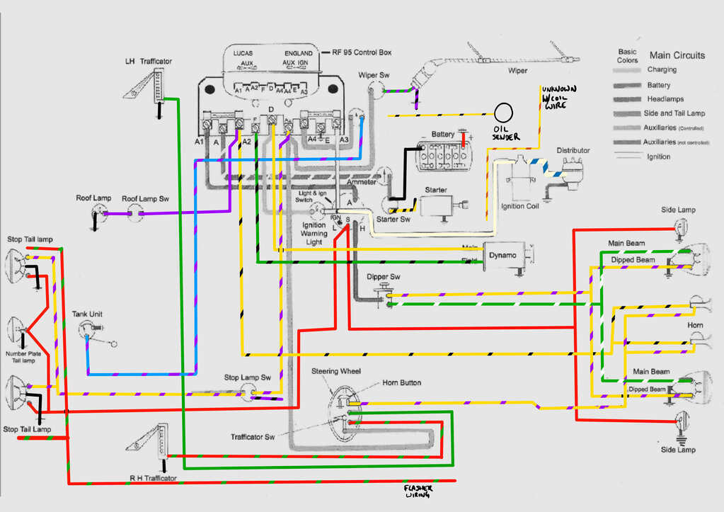
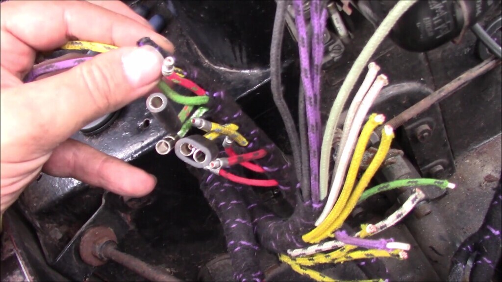
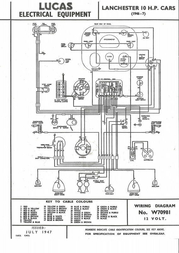
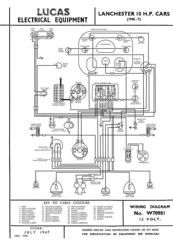
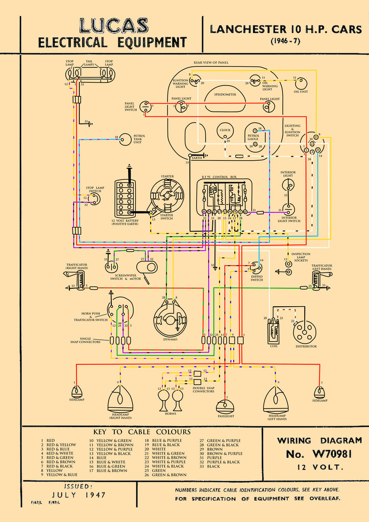
Quite a long update this one, just to warn you in advance. Lots of images to illustrate what was being done. Hopefully this will help if you're working on a LD10 or anything of similar vintage since this car is apparently fairly conventionally wired for its age and construction type.
Pat and I had spent some time figuring out what wires went were. Some of it was more obvious than others and, had we been working with a car that was a clean slate, I imagine this whole process would have gone much smoother. Easiest item was the wiper motor wires. The grommet disintegrated which is why it's not there at the moment.
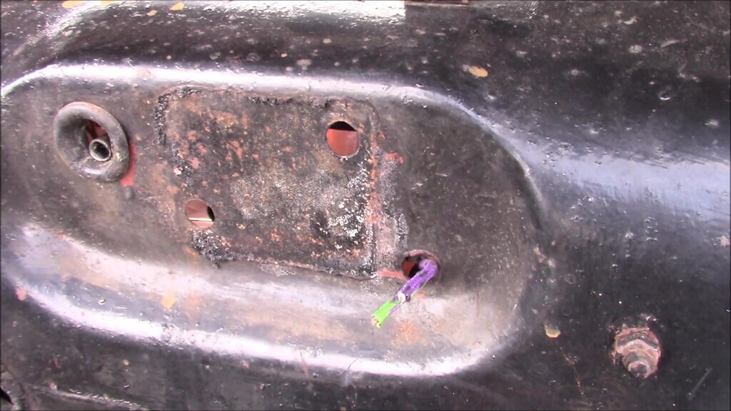
Much of working out the dashboard portion of the loom was a case of laying it down and seeing where the wires lined up with things. Because almost nothing on our car was original in this area and we had no references to work from to tell us what went where, it was a case of applying the logic of wiring colours and lengths. Once we had the wiper motor figured out, the oil pressure sender made most sense next.
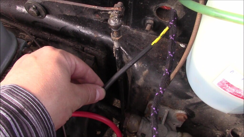
Normally it looks like this runs through the P clip next to the fuel filter. The filter is a later addition and not original and to slacken off the P clip to feed the wire through you need to remove the filter since that's the only way to get to the bolt for the clip. Removing the filter is a two person job, or a one person job if you've got longer arms than I do.
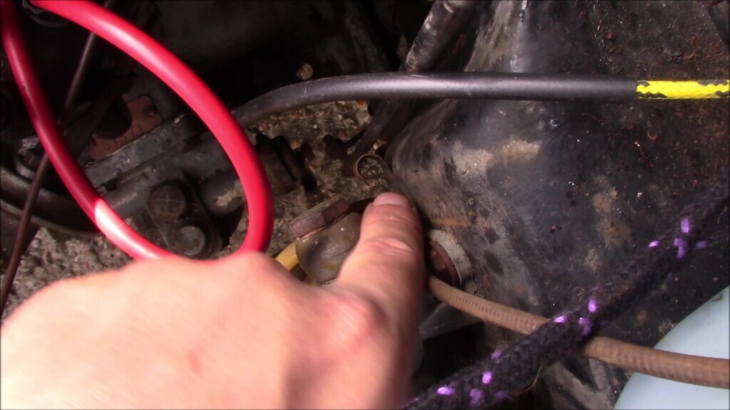
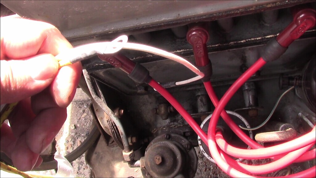
I haven't connected anything yet because this was the first dry run of putting the wires through. I wanted to know routing was correct before committing to fixing things in place. Next up was the coil wires and this one is a little confusing. There's a yellow and a white, which seems correct for coil, and the length is good too. However, on our car it had one wire to the loom from the coil, and another from the coil to the distributor. The new loom you can't do that unless you're supposed to split the white wire so that it can run loom-coil-distributor. I didn't know (and still don't yet), so I just left the wires loose for now.
I then got some fresh grommets (these weren't provided with the new wiring) to put in the bulkhead where the new wires were going through.
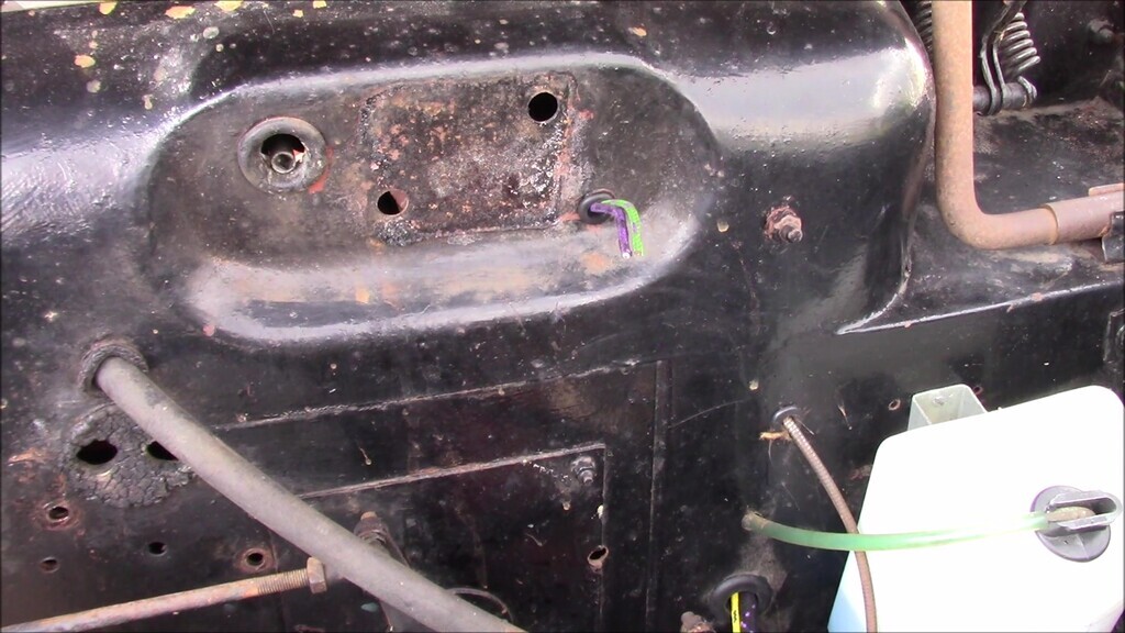
Then it was time to try and figure out how the wiring in the engine bay linked up to the wiring in the car. There's no split at the bulkhead, so all of the wires in this section of the harness has to be fed through the relevant holes in the correct way. I didn't know what that was. I'd looked at as many photographs as I could find of other LD10s and that wasn't many. I trawled YouTube to try and find any videos showing this part of the engine bay and again, barely any information at all. So I was flying a bit blind on this one. I already knew the new loom was likely to be difficult to thread through the original holes purely because of the extra bulk it would have, but I didn't know how it physically routed. I guessed that because the bulk of the wiring junctions was on the inside of the car it probably made most sense to thread the harness through from inside the car into the engine bay. That way, in theory, I'd have the lowest chance of damaging the new harness. This would prove to be incorrect.
I began my journey by threading some of the harness through the top left hole in the bulkhead, and some through the hole that the temperature sender capillary tube and the speedo cable went through, facilitating the removal of the temperature sender (this still hasn't been refitted due to fragility, it's stored safe in the house out of harm's way). This was because I thought some of the wiring made sense to go through there because of how the new harness lined up with the bulkhead holes. This was incorrect. I also learned that the provided grommets were very difficult to thread onto the harness, however you went about it.
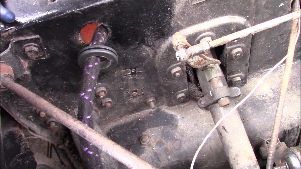
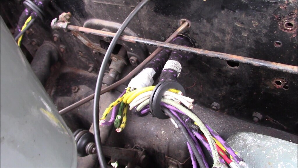
The more items I then tried to line up, the less this seemed to be the correct route so I had another go, putting the bulkier junction through the top left hole this time. This was also incorrect, but only partially.
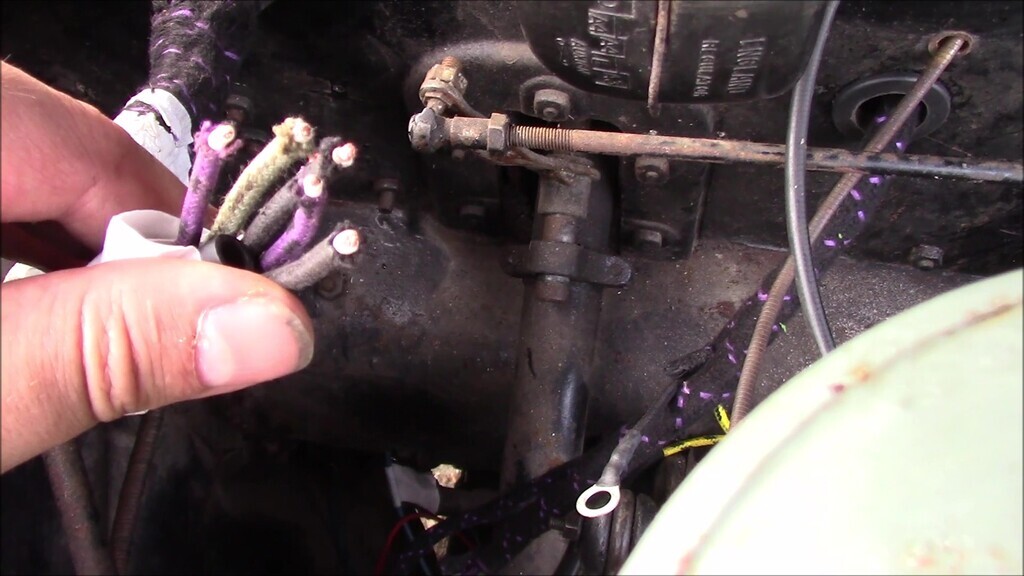
There was a lot of head scratching and then, finally, I found a reference image from an Australian auction. It was a tiny blurry little thumbnail but it showed a car with original wiring intact and routed as per factory. This meant I could see that pretty much all the wiring went through only the top left hole of the bulkhead. What took me a while after that to figure out is that you have to feed the whole harness from the engine side, through the top left hole, and into the car. This is the only way to get all of the wiring where it belongs. It's still not that easy since it's a cumbersome thing that wants to snag on everything, but had I known that from the start it would have saved me a lot of time.
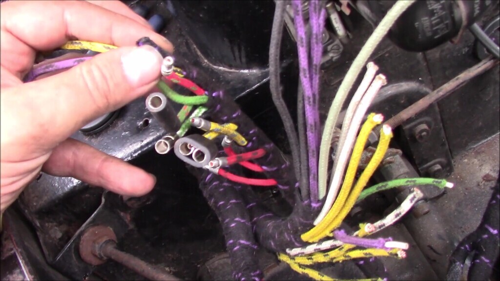
The reason you thread the wiring through that way is so that the junction to the next section sits about in line with the top of the steering column. There are two runs of wiring that go along the steering column, one that goes through the inside of it for the indicator switch and horn, and another that is held to the outside of the column that goes from the bulkhead down to the chassis. The big mass of wires with no connectors go to the voltage regulator (it's going to be fun working out exactly which of those goes where, I'm sure), and when you're inside the car, the wiring should sit up near the top of the bulkhead held in place with P clips. As long term viewers will remember, the wiring the car came to us with was loosely draped over the heater.
The wiring that runs down the steering column exits the car through a hole in the inner wing at the steering box. A pair of yellow wires spur off up to the horns, and the rest of the wiring is for the lights.
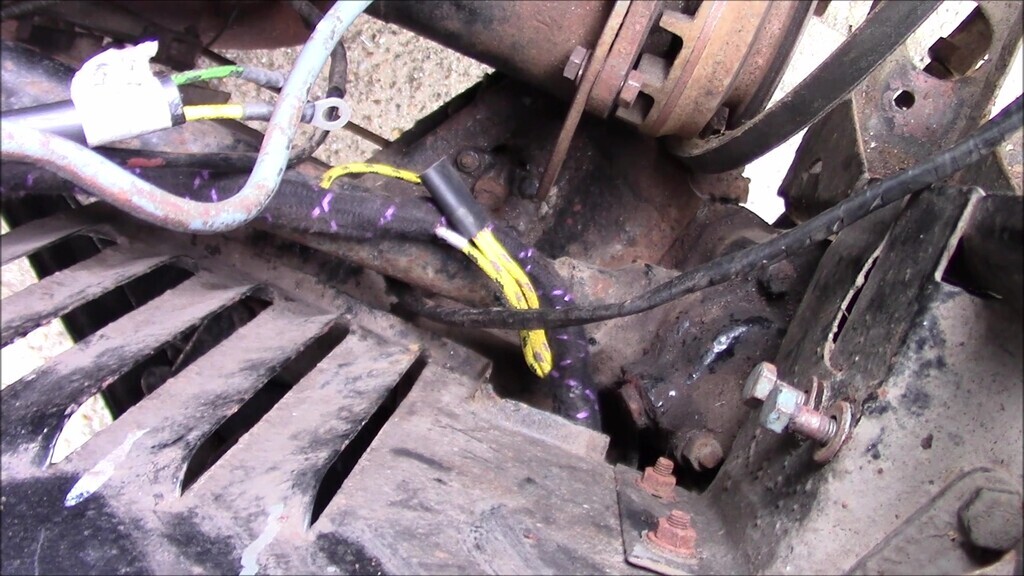
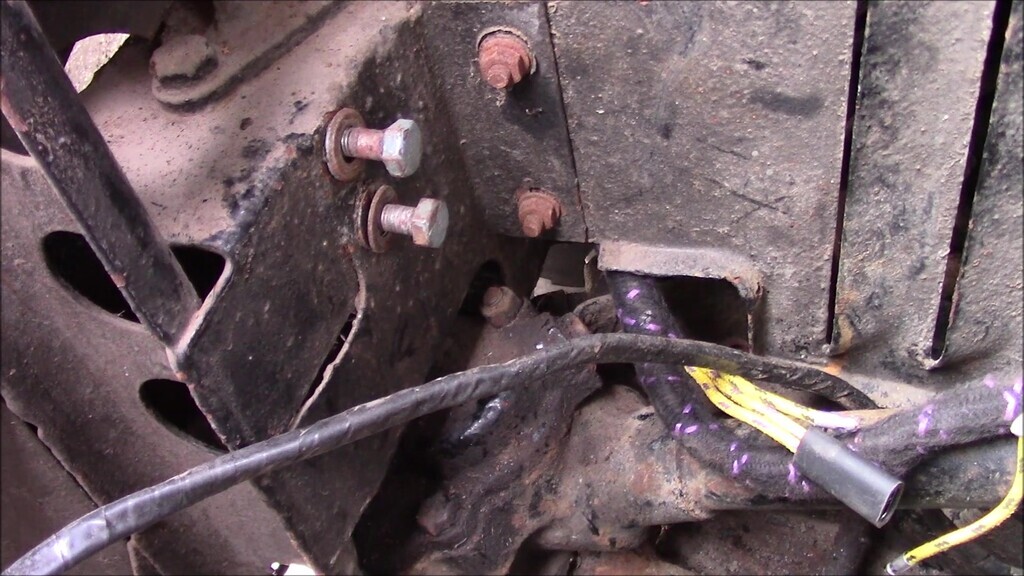
This wiring then runs under the front of the car before just the spur for the horns comes back in through a hole in the passenger inner wing.
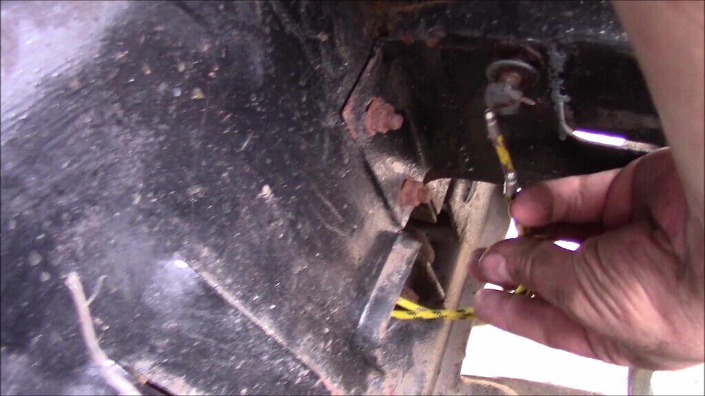
On the other side of the passenger wing (wheel side, rather than engine side), the wiring goes through a box section to keep it secure. One branch goes up through the top of the box section along the wing support rail. There's a P clip in the top of the brace the holds down the wiring. One wire goes to the sidelight, the other two go to the headlight.
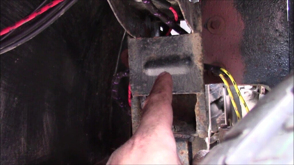
When we got the car, the mix of original and modified wiring was cable tied to the underside of the radiator support. I suspect there's supposed to be three P clips where those bolts and big washers are to hold it in place instead.
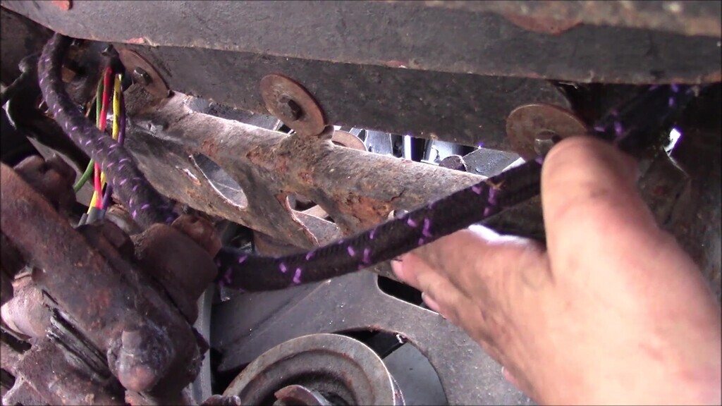
With all that routed, I could take a step back and a bit of a think about where I was at with it. This area was looking more like it should, and even though things aren't connected yet, it looked a lot tidier than when it arrived. I felt like I stood a chance to work through this logically now at least.
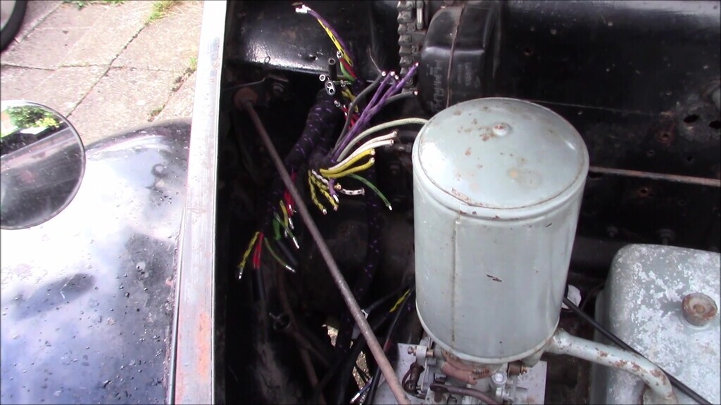
For the lights at the front, the single red wire goes to the sidelights, pushes up through the centre of the bolt that holds it to the wing and out into the light unit. We've got to get the new dual function LEDs for in here, and figure out what we're doing about how we earth them properly since reinstated the old repair of a thick twisted copper wire isn't really that reliable.
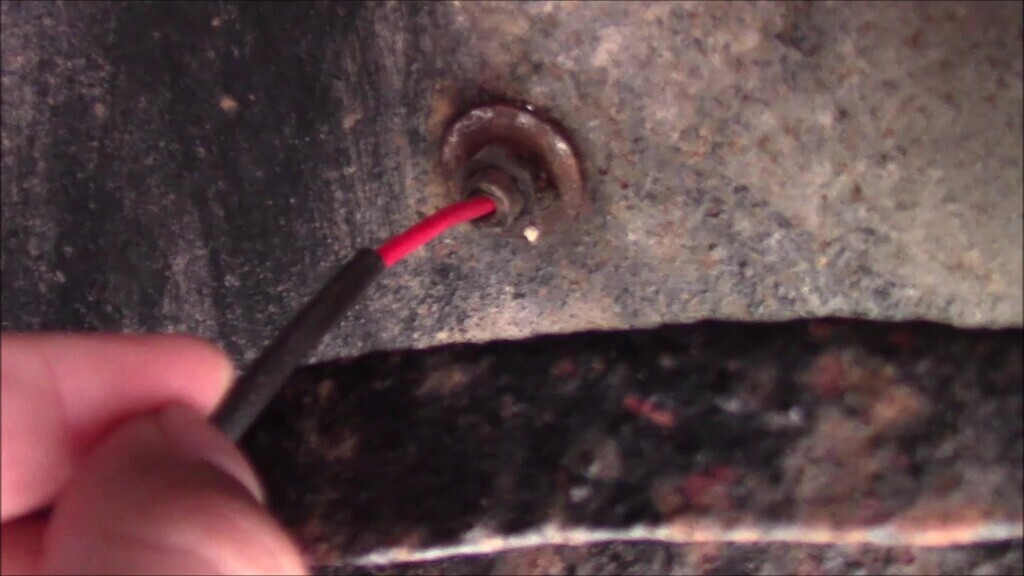
For the headlights, it's a yellow and a green wire.
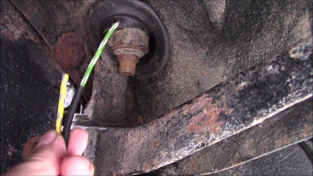
Going from the box section on the inner wing on the driver's side, you can follow the wiring back from the lights, through the inner wing, and into the engine bay.
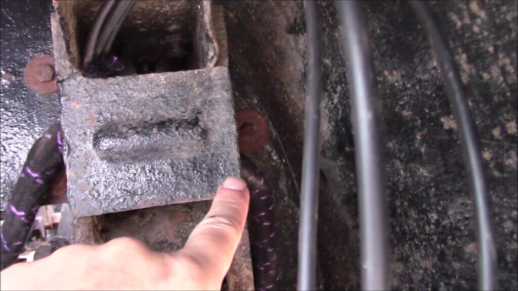
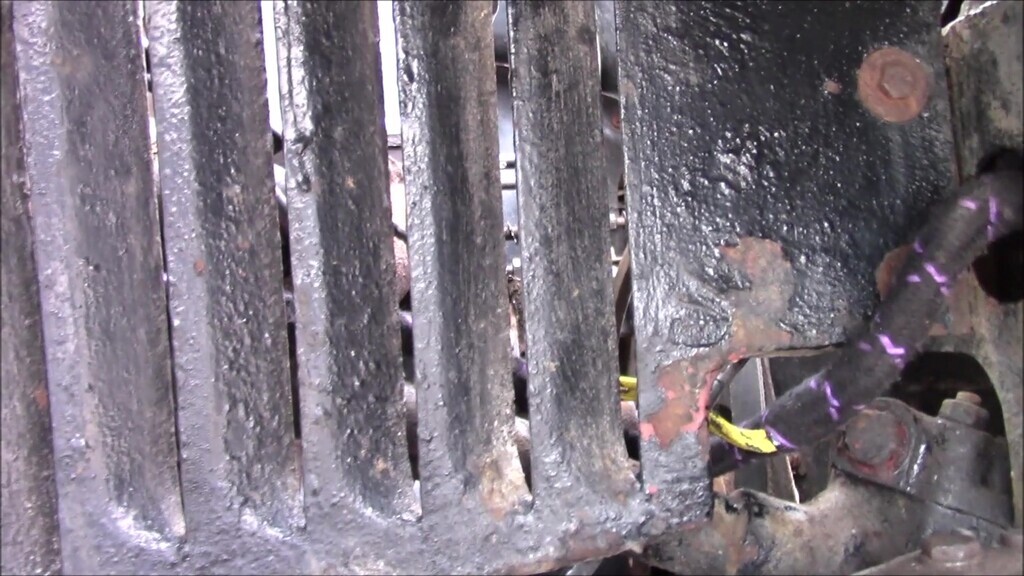
It then branches up to the steering column to join the dashboard section of harness. There's a spur off for the dynamo and starter motor, and then there's a branch that goes down into a closed box section of the chassis. You can see a random blue-ish wire here from a previous re-wire.
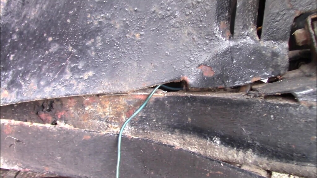
I now had as much of the front as I could figure out the next thing to do was to head to the back of the car again. The only thing in the middle of the car was the brake switch wiring but to get to that I'd have to remove the wiring that runs along the drivers side chassis rail. I couldn't do that until I'd disconnected the fuel tank and figured out how the wiring joined up to that and the wiring for the lights in the boot. With the rear wheel off and the car on an axle stand it's pretty easy to see everything you need to get to.
To the left in this shot is the fuel tank, I pointing at the chassis crosstube the wiring goes around (more on this in a moment, to the right of my hand is what I believe is the rear brake rod actuator, and ahead of that is off course the differential and rear axle.
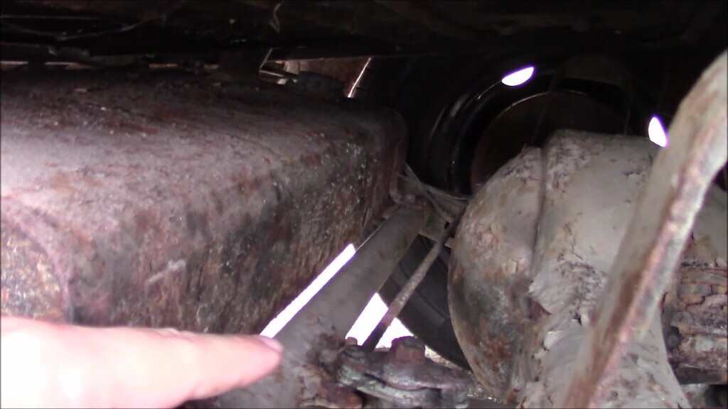
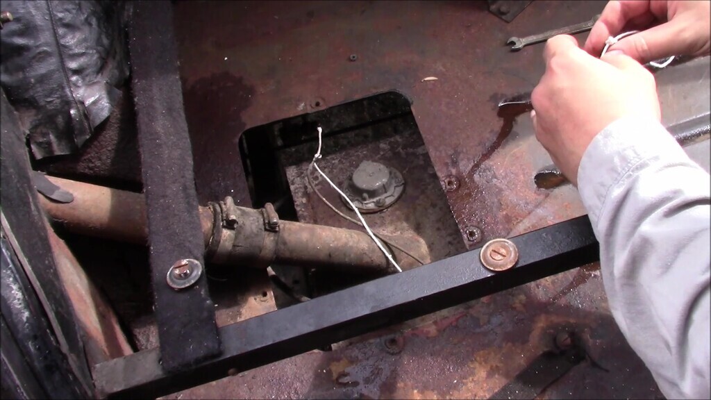
Where I'm pointing now is the fuel tank sender, which works so we shan't be disturbing it, and that needs to be disconnected. Happily, there's an access hatch in the boot for this very purpose. It does seem a little odd that the sender is on the opposite side of the tank to the main wiring, but perhaps there's a sensible reason for it being nearer the filler neck?
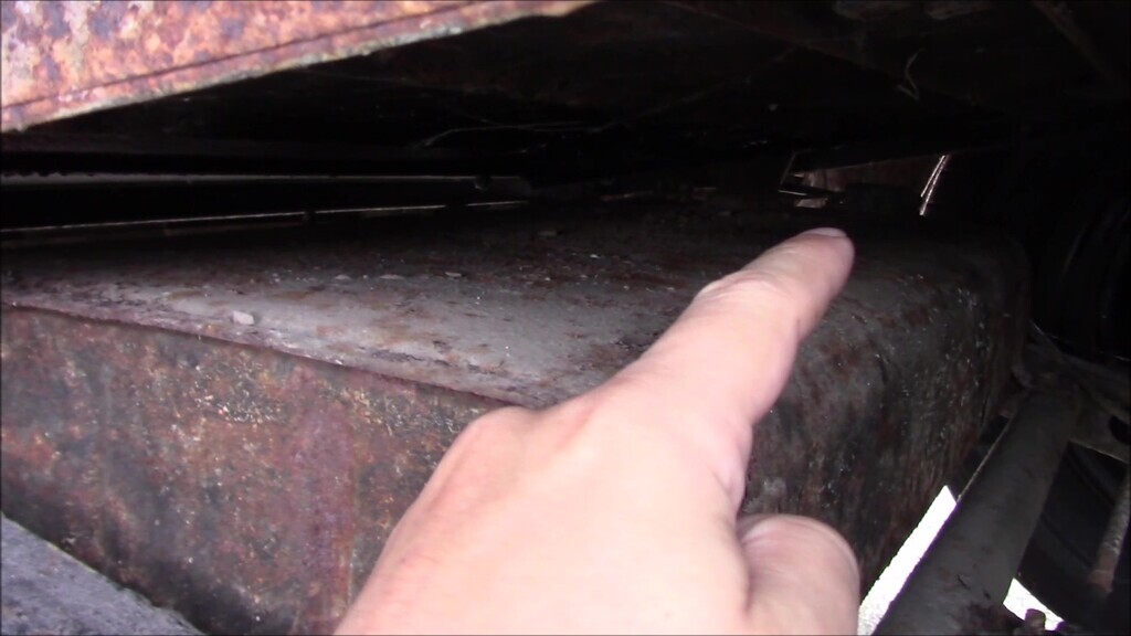
I wanted to know how the wiring actually ran to the bullet connecters that were tucked into the corner of the boot, pulled out under the car here since everything was being unthreaded. This part of the wiring is original, so this is what Lanchester installed back in 1951. It's very brittle and stiff for the most part.
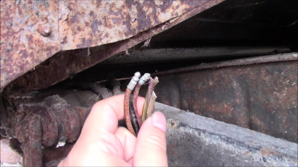
I'd had some confusion with the new harness in that there was a very long run of wiring that contained three wires with bullet connectors on the ends. From the colours, it looked related to the lighting. However, to my knowledge up until this point, I thought there was only one run of wiring down the chassis and I already had that accounted for. Now I was at the point I was dismantling things, I could see what that wiring was for. The old wiring runs inside the chassis rail, and then loops over the crossmember that runs between the fuel tank and the axle. It has a plastic-y sheath over it where it sits outside the chassis, so it's not immediately apparent that it's wiring.
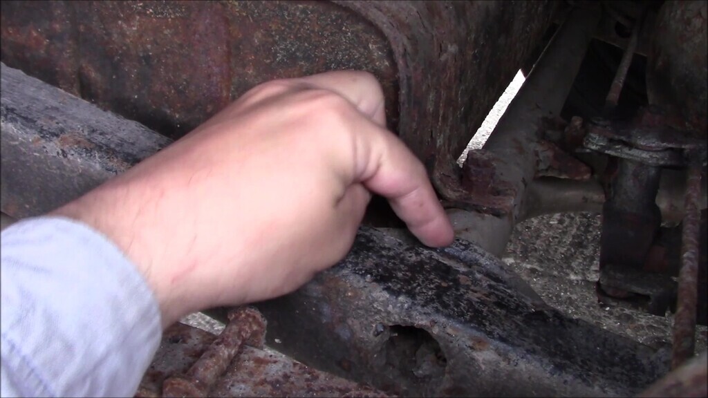
What I didn't know is there's a second run of wiring that loops underneath the same crossmember, also with a plastic-y sheath covering it. This does a good job of keeping the bulkiness to a minimum and makes for a very tidy routing given the design of the chassis.
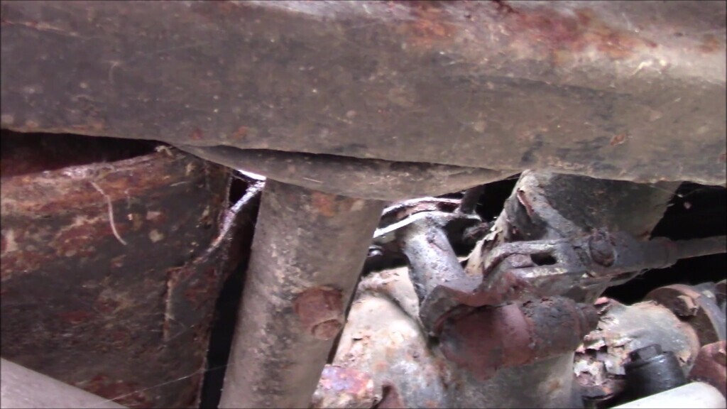
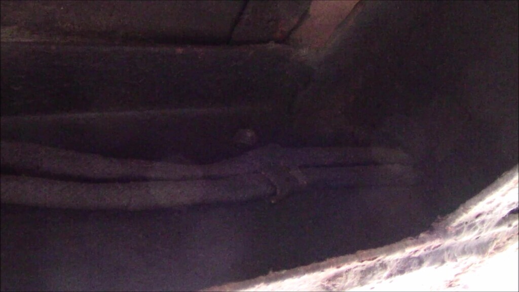
The other thing I hadn't realised when trying to find the wiring previously is that because I'd been looking in the wrong place, I hadn't seen the two runs of wiring that are clamped to the inside of the chassis rail. There are a few braces along the length of the chassis that have sort of leaf shaped holes in them that guide the wiring, and clamps at intervals that keep it in place. It's all very dark under there.
That figured out, I could remove the fuel sender wire. There's an access hatch for this in the boot covered by a pair of pressed steel plates with a rubber gasket that go around the filler neck. If the intermediate wooden floor is still installed, there's a hatch cut in that too that you can remove.
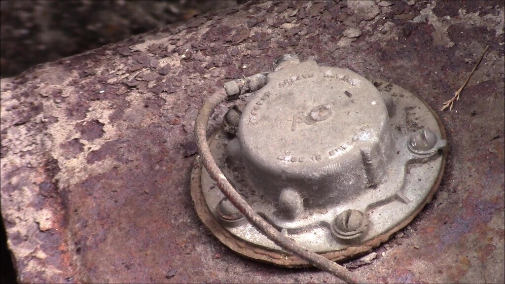
The wire has an eyelet on the end and is simply slid over a threaded shaft and secured with a nut. Once it's removed, I tied some string on to it so I could unthread it. I found that the wire is held to the rear cross tube with two large metal band clips and the centre rear bracket for the fuel tank.
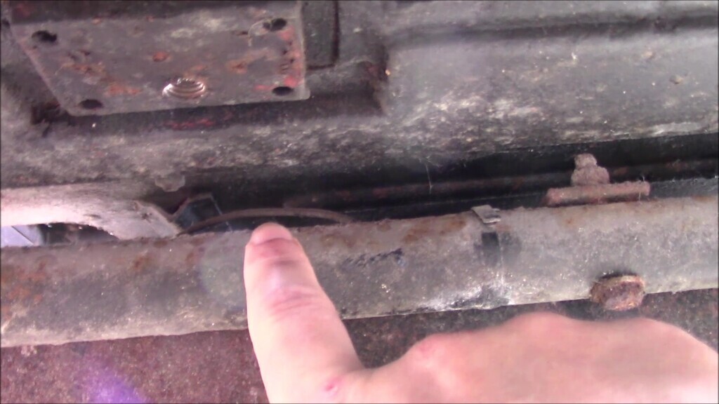
Then it's a case of finding any tools that fit the Imperial fixings to undo them. I only had two spanners the correct size, and fortunately the right shape too. I was quite surprised at how easily the nut and bolt came undone, I fully expected them to be rusted solid.
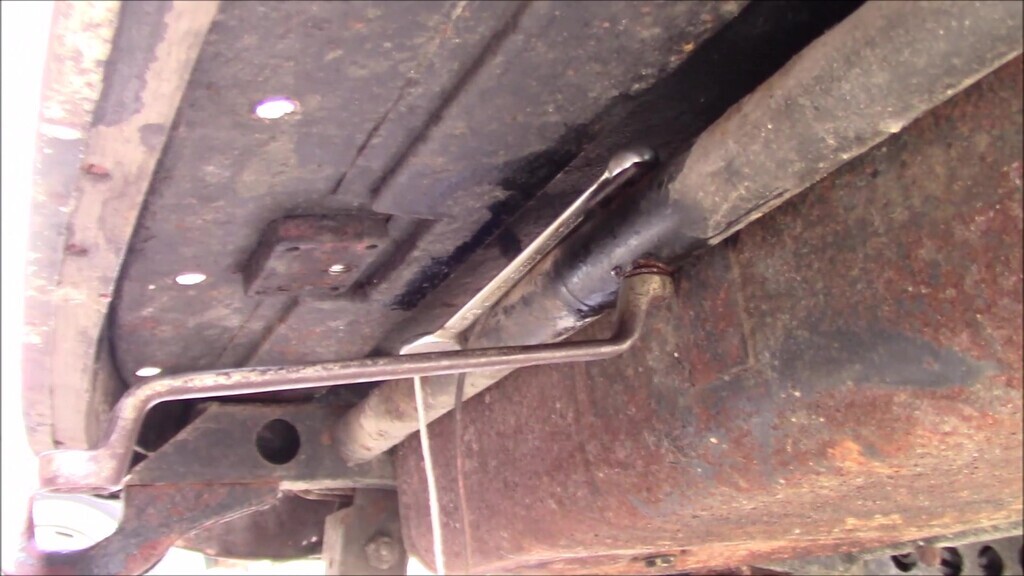
With the wire unthreaded and the string taking its place I could then figure out what was going on with the rest of the wiring at the end of the chassis. I also learned at this point that the fuel tank had to come out because otherwise you can't actually move any of the wiring. It's not that the fuel tank is pressing on the wiring, just that there simply isn't enough space to get in with your hands to move the wiring out of the chassis.
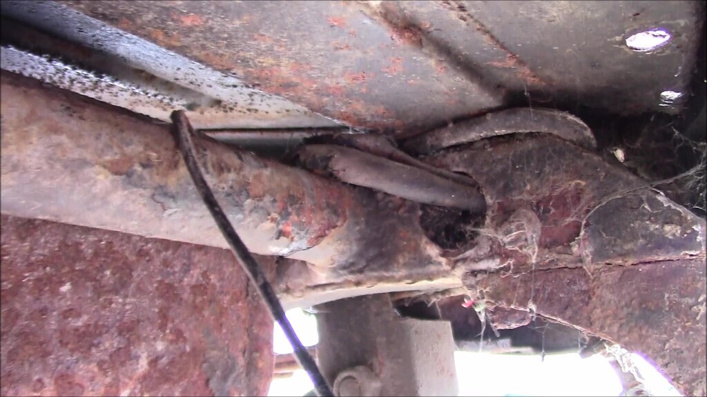
That meant disconnecting the rotten filler neck connecting hose, something that will be easy and sensible to replace. That also gives us access to the worst of the rust on the back end which is just this simple bit of fabrication needed to the inner arch. Duct tape over the filler neck to prevent dirt going in the tank since I can't put the cap on with that being attached to the other part of the filler neck.
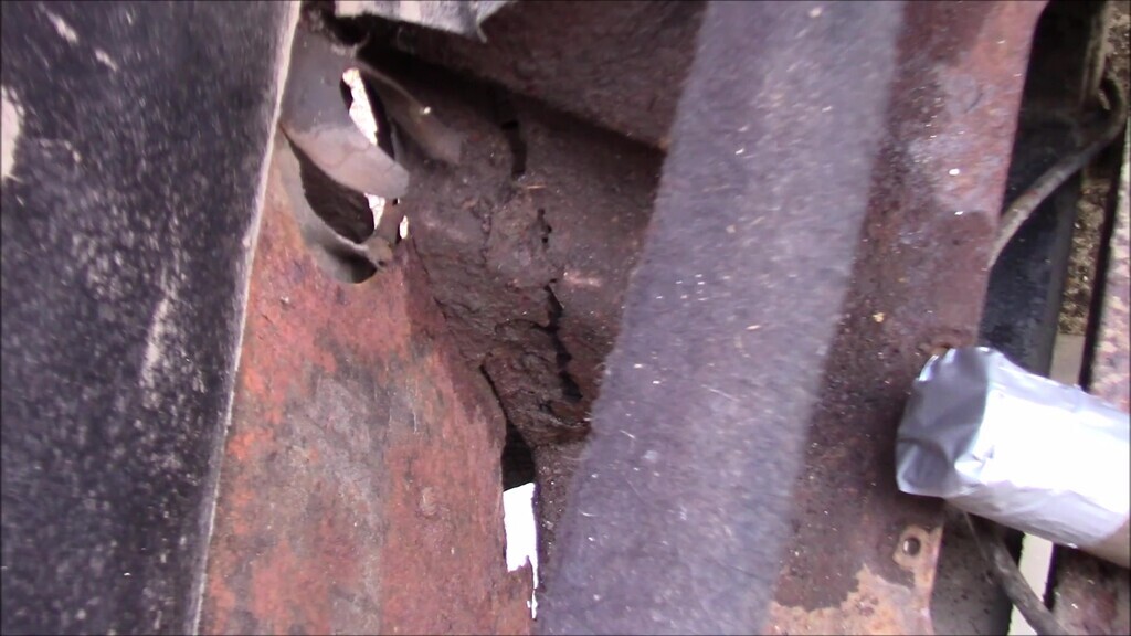
The tank is held into the car with one bolt in the middle at the back through the rear chassis crossmember, and two going through the chassis crossmember the wiring loops around. Again, the other bolts came undone surprisingly easily and the tank was then ready to remove.
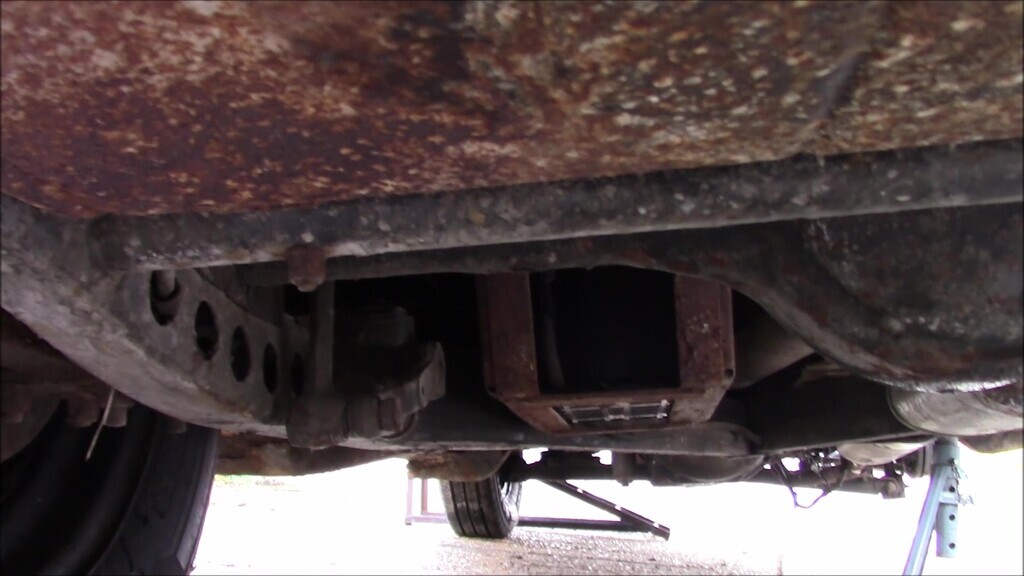
Or so I thought. I found out very quickly that the exhaust needs to be disconnected to allow the tank to drop out. I was time conscious when I did this job, not least because it kept suddenly raining very heavily without warning, so I just moved the tank aside and later I'll drop the exhaust so the tank can be removed and repainted properly. At least I could get to the wiring and start figuring out how that came out. There was a nut and bolt going through the end of the chassis which I'm still not entirely sure of the purpose for. There appeared to be a wire going to it, and there's a stub of what might be an auxilliary light under the car in this sort of area, but no switch or wiring for it anywhere in the car.
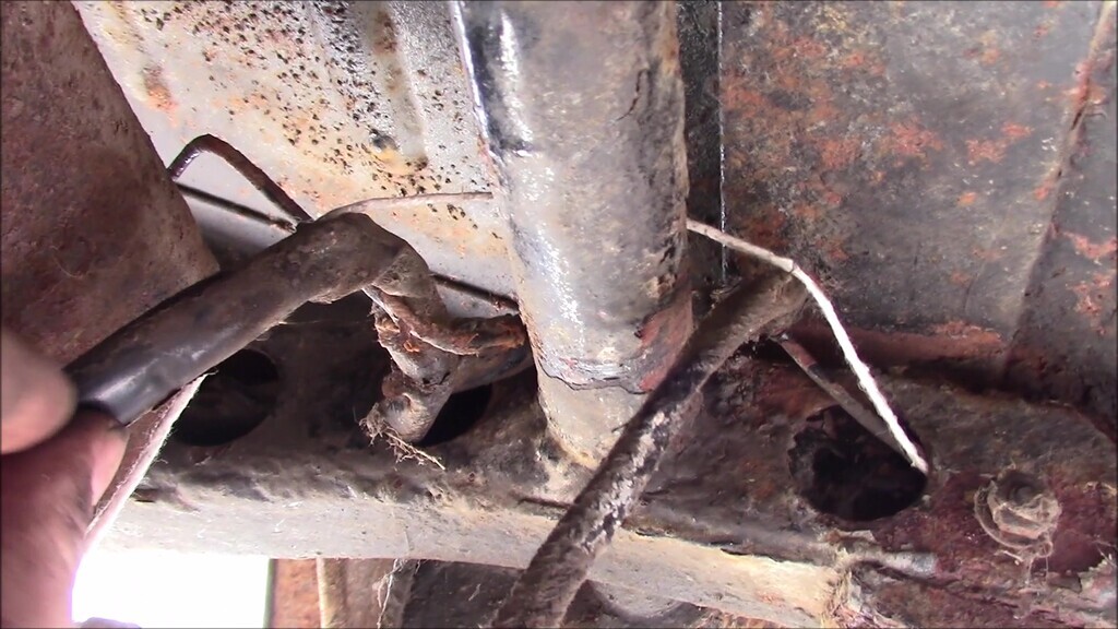
There was a lot of fiddly and dirty work attaching strings and persuading decades old wiring and dirt to let go and come free. I wore eye protection throughout this job because I like my eyes and don't have a spare set. I should have also put something over my ears to stop rust and dirt going in them, it was one of those jobs. Eventually I had the wiring out and I had to remove the brittle old plastic-y sheathing that kept bunching up and jamming the wiring as I was trying to remove it from the chassis.
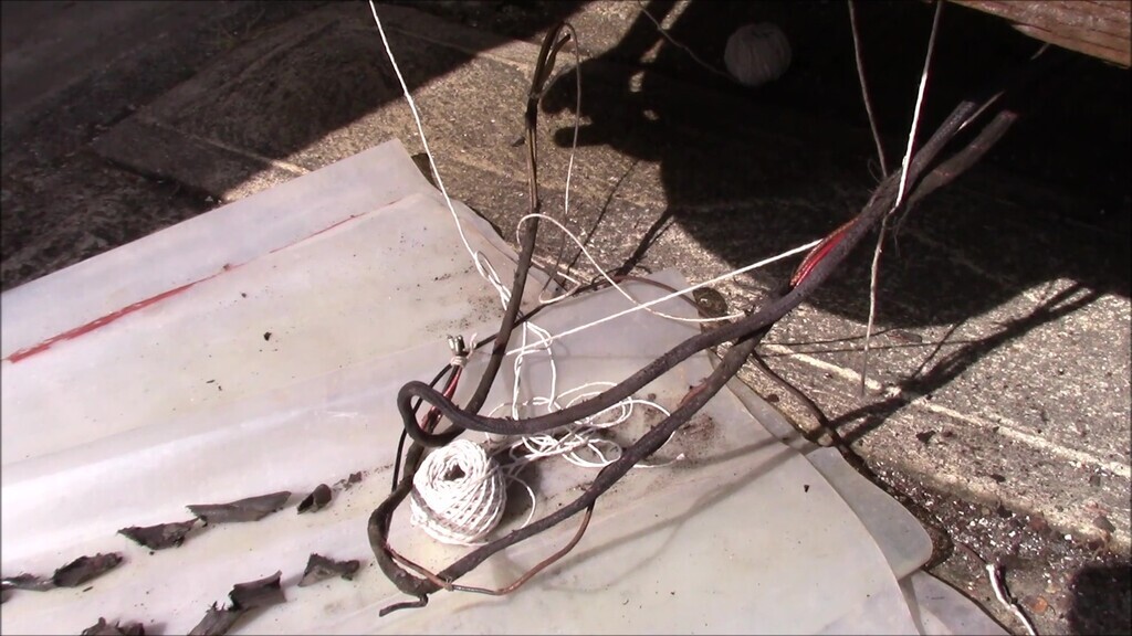
It's not very easy to unthread the wiring from the back of the chassis because all you have for access are these little holes. Even with the wiring clips unbolted in the open section of the chassis, it was still slow going. Because I also had to pull the string through, I had to be careful not to snag things, and because I was dodging the sudden downpours and trying to keep the camera safe, it was a bit of a chore to do.
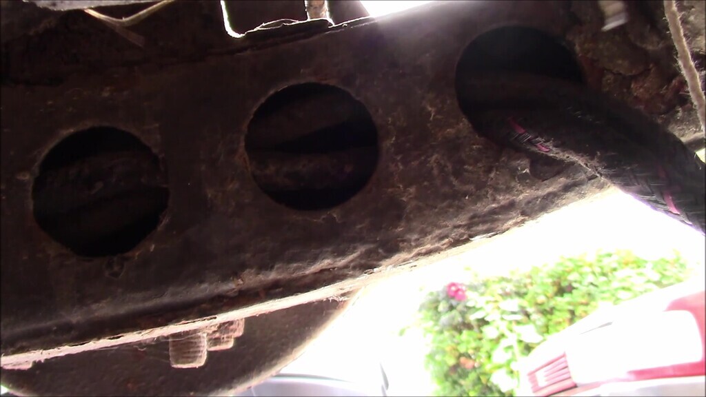
The wiring is held to the chassis with B clips (that's what shape they are, like a P but two bumps) located under each of the bodymount/outriggers. It's a nut and bolt rather than a captive nut, so they are a bit fiddly to remove. Once you've removed the clips, you then have to make sure as you pull the wire out it doesn't get jammed in the narrow part of the vertical guide holes (not the same as those circular holes in a previous photo) in the chassis, and even more careful of the string which is hard to keep out of the narrowest pinch point.
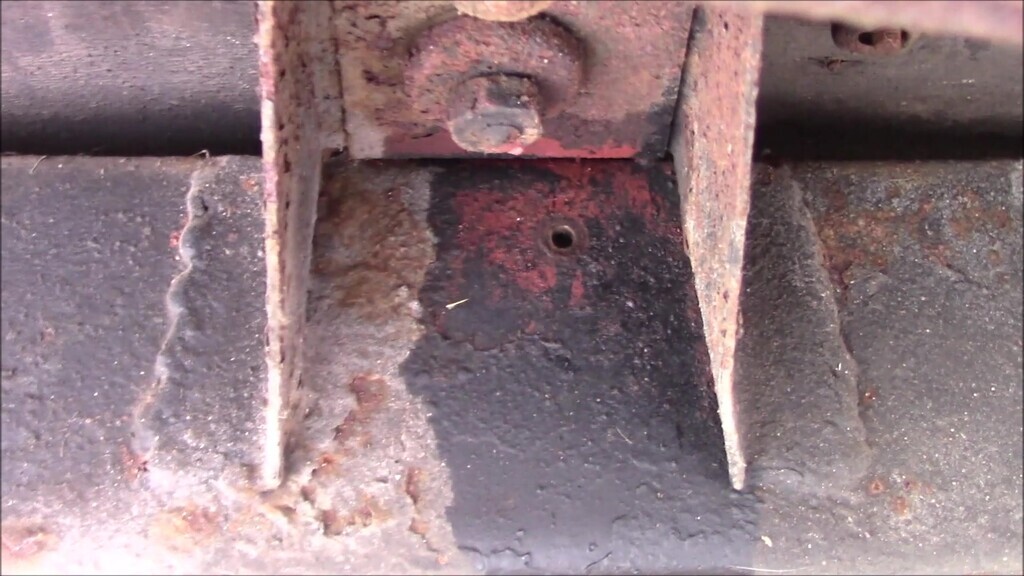
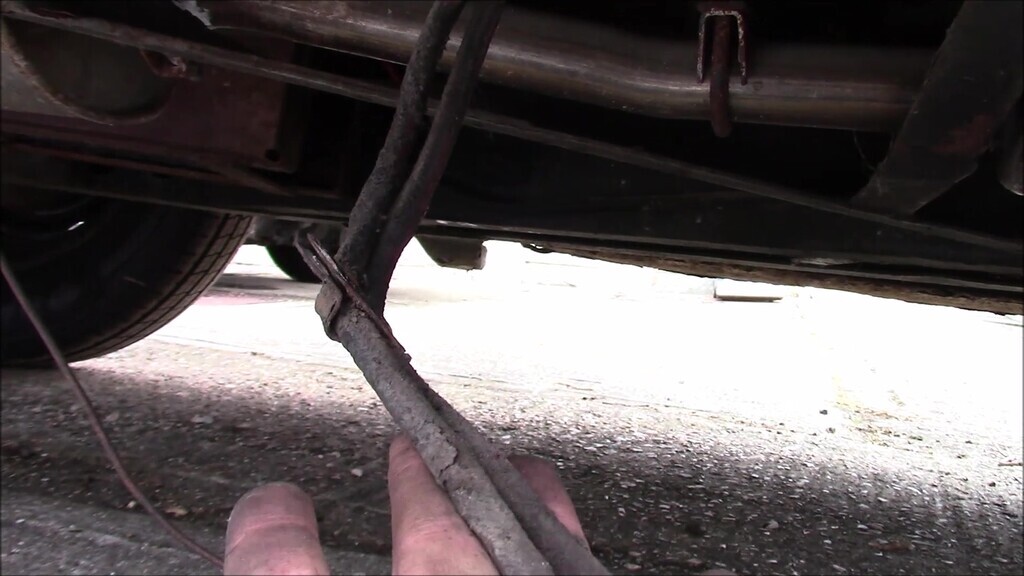
Eventually, I'd freed the wiring as far as the B pillar, I had strings run to preserve the wiring route, and was ready to work my way forward for the last bit of the old wiring removal. That will have to wait for a future update, this one is quite long enough.


