We finally get the first new pieces of wiring into the Lanchester. This is one of those jobs that is a lot easier in theory than in practice, especially when it's a job you're new to. First job was to remove the boot lid. Someone has had this off before, both hinge pins were only in half way so Pat and I assumed that they were the sort of hinges you had to knock the pins out of to get the boot lid off. First one came out without too much hassle. A skinny screwdriver and a hammer were all that were needed. One brass pin removed, and looking just a little bit bent. We'll tidy it up before reinstalling it.
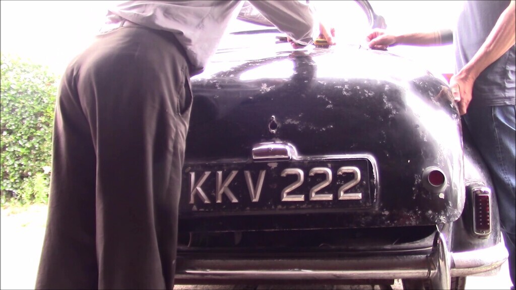
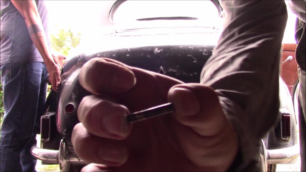
The second pin put up more of a fight. So much so that after ten minutes of solid hammering, application of lubricant, changing of positions... it was clear it wasn't coming out easily. Later on we learned the pin itself was actually bent.
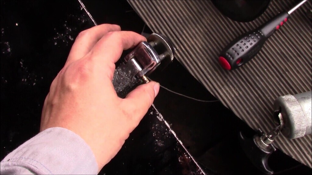
Of course, it was only after the pin being so stubborn about coming out that we were encouraged to look for hinge fixings and we found the two nuts that are sunk into the wooden frame. Once those were unbolted, the boot came off no bother.
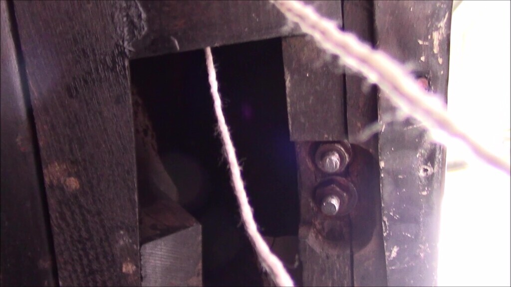
As with many things on this car, the boot lock mechanism is a fairly basic thing. Pat and I aren't sure whether or not there should be a trim over this area. We'll likely make something out of black millboard or similar to match what's already used in the boot since it seems a bit strange to leave this area exposed and there are some vacant holes in the aluminium surround that are in about the right place for fixings that might hold a trim in place.
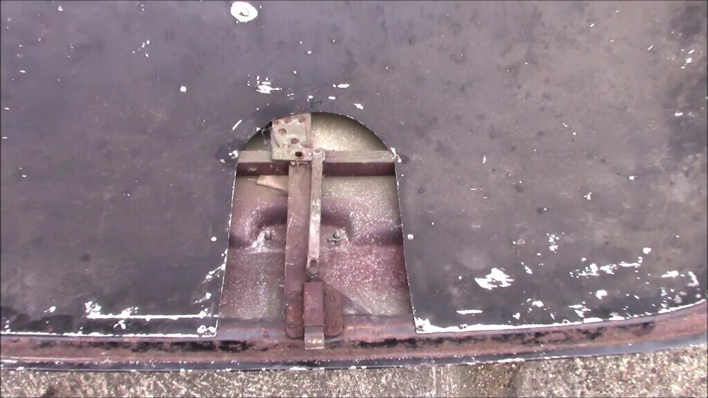
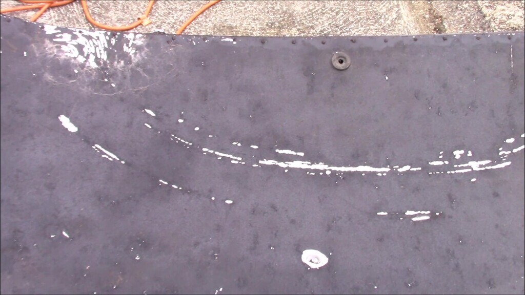
The boot has been re-wired at some point, badly, and not in the same sort of materials as has been used at the front of the car. Here we've already removed the wiring, but you can see the grommet it should pass through, and the puncture in the aluminium skin that needs dealing with. The aluminium trim on the inside of the boot lid is held on with dozens of tiny once-chrome-plated flathead screws.
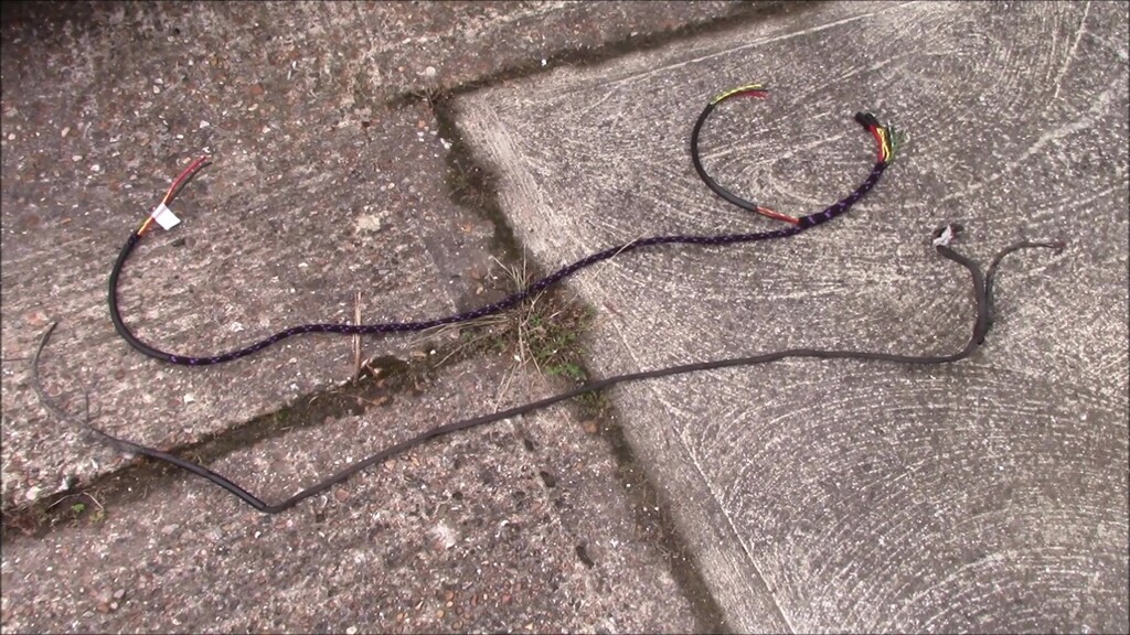
Pat and I had spent quite a lot of time trying to figure out what bits of the wiring loom went where. The wiring diagram we have for the car seems accurate except for the colours. The colours of the original loom don't match the new wiring loom, and neither looms match the diagram, so that really slowed us down on figuring out what went where. Additionally, the modified sections don't match the old loom, the new loom, or the diagram. To further confuse matters, the only help provided for the new loom is in the form of a colour key on the website of the company that provided it. There's no indication of which physical section of the new loom is for which section of the car, ie: rear lights, engine bay, dashboard, etc. So there was an awful lot of guesswork involved. One clue was the plastic sleeving on the wiring since this is used in areas where the wiring is both exposed to the elements and in an area it's likely to chafe on metal. Parts of the loom that are just plain cloth wrapped in the black and purple are usually (but not always) interior sections. Here are the new and old sections of the rear lights wiring.
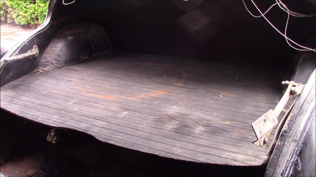
To fit the new wiring, I thought it best to remove the intermediate boot floor. In theory, this should just be a case of undoing some screws and lifting the board out. The rubber mat had thankfully not been glued down and is likely not the original.
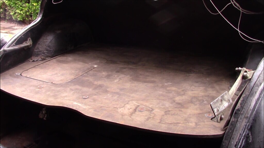
There's a small hatch set into the main board, it wasn't clear what this was for at first since even though it's about the size of a battery, the battery lives under the rear seat.
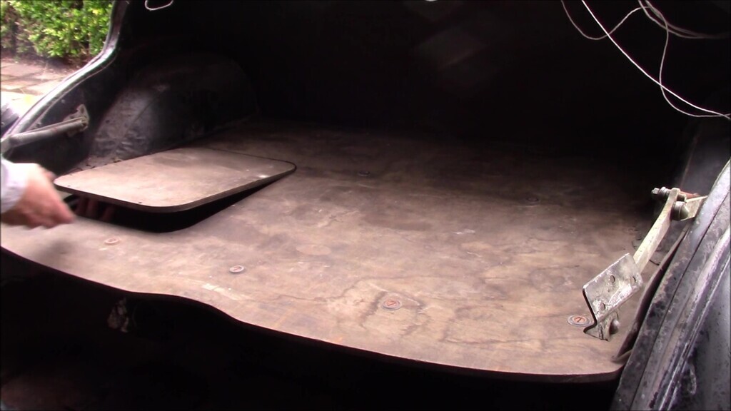
When you look through the hole you see two pressed steel plates with a rubber skirt, this is obviously a part of the floor that's removable for some reason and the rubber skirt is to keep the weather out.
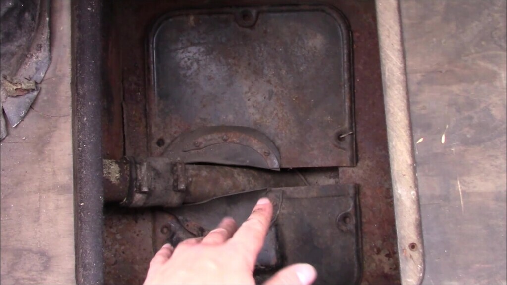
The fixings for the plates were missing and none of the fixings that came with the car were the right sort. Anyway, what's underneath here then?
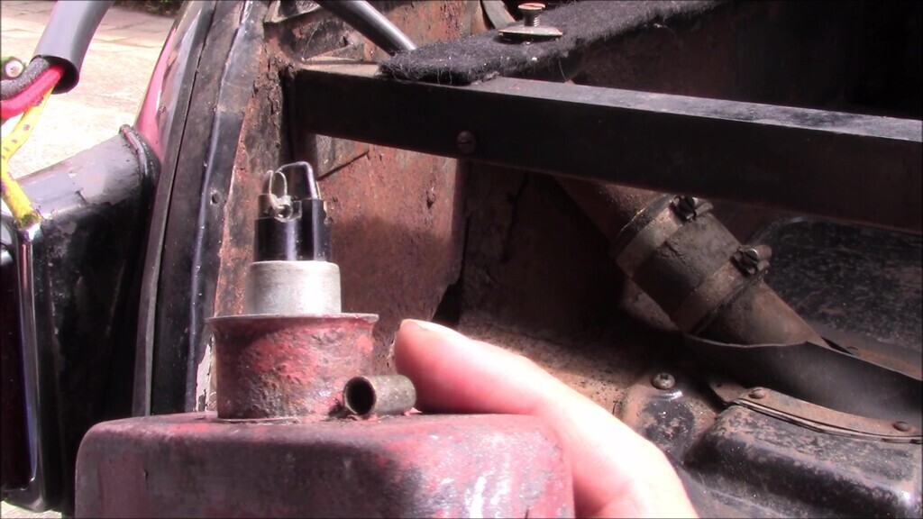
Ah yes, the fuel tank, or more specifically, the fuel sender. This gives you easy access to the main fuel feed line that starts at the top of the tank and runs all the way down the chassis to the front of the car. It also gives access to the only wire going to the fuel sender. We know the fuel sender works so we didn't disturb any of this at the moment.
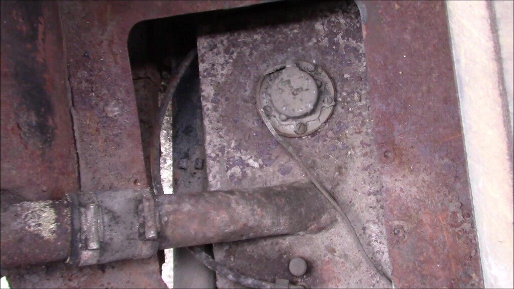
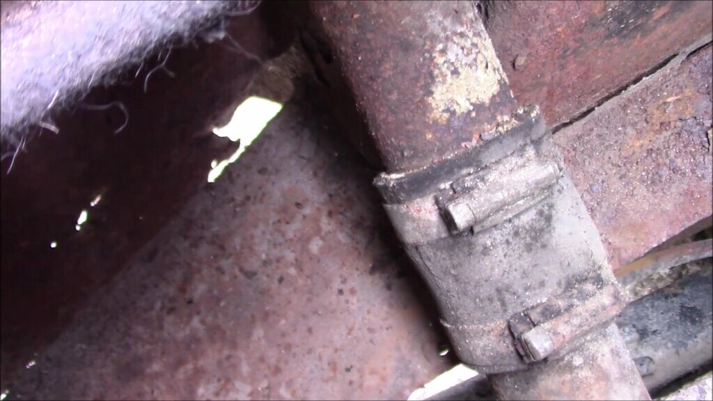
We also found out where the occasional smell of fuel was coming from. The large diameter hose that joins the filler neck in the wing to the filler neck of the tank has perished and split. We'll be replacing that before the car hits the road proper.
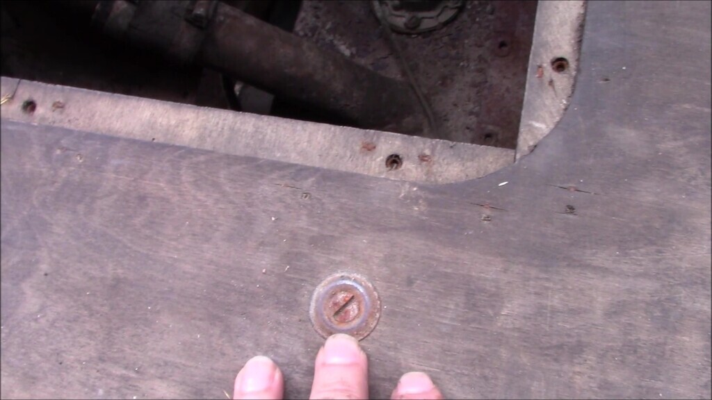
Next to remove the plywood board. This is held down with quite a few bolts (or are these machine screws?) with cup washers. They all came undone fairly easily. The board required a good tug to get it free and once out it gave much better access to the boot floor proper. The main obstacle to getting the plywood out easily is the millboard that the side hinges bolt to, something I can't remove because the fixings seem to have rusted solid and I can't get heat into them without damaging things. A case of working around them for now.
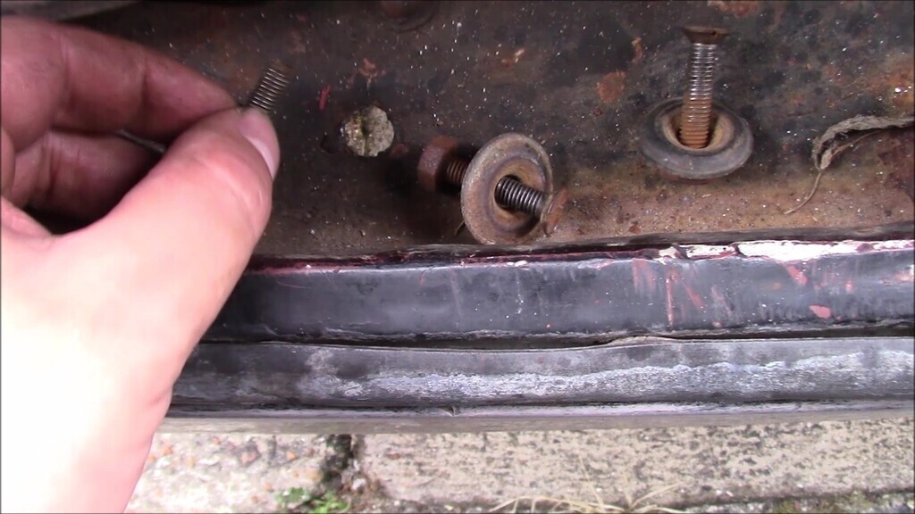
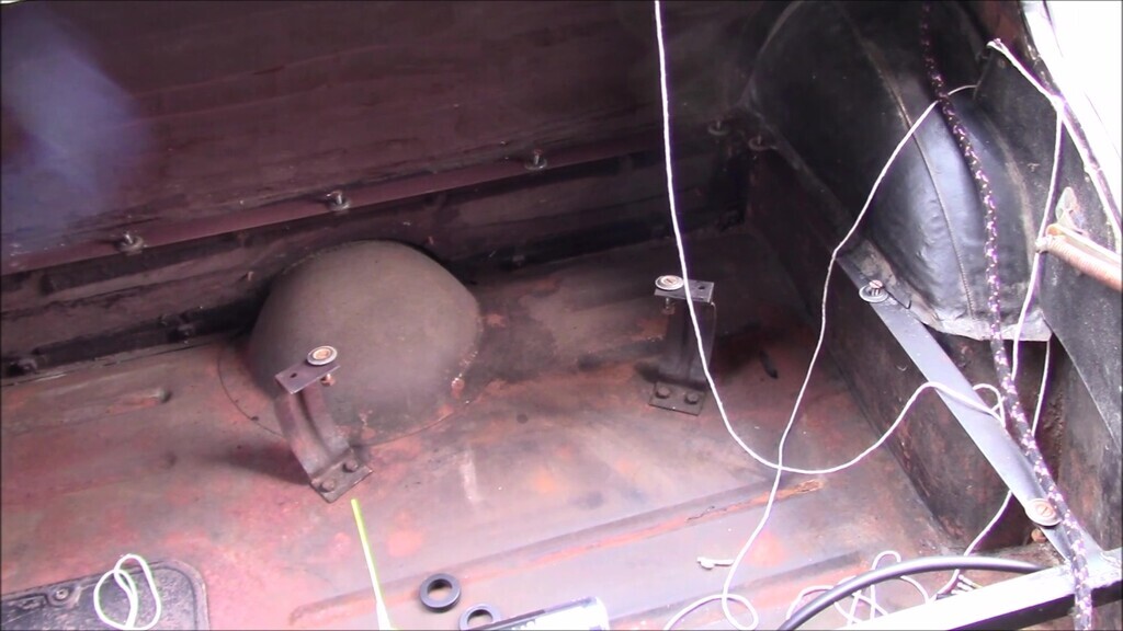
The awkward thing to remove where the bolts for the spare wheel stops. These are two brackets that are shaped so that your spare wheel doesn't push too far back into the space. My arms are only just long enough to reach to get a tool on the nut on the underside and use a screwdriver on the top side.
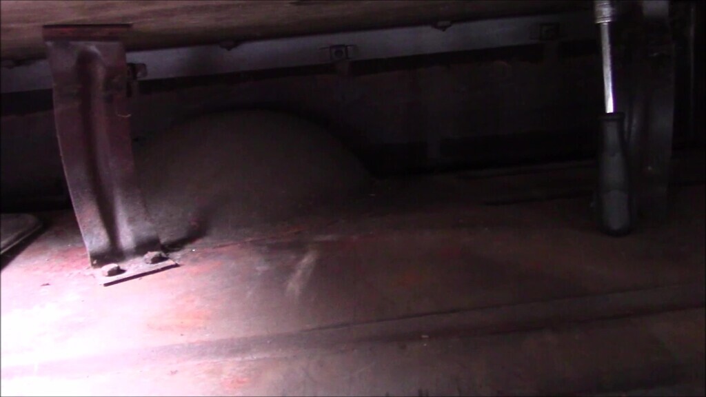
All that finally out and we could get a proper look at what was waiting underneath. Honestly, I was expecting quite a lot of rot and mess in here so I was very pleasantly surprised.
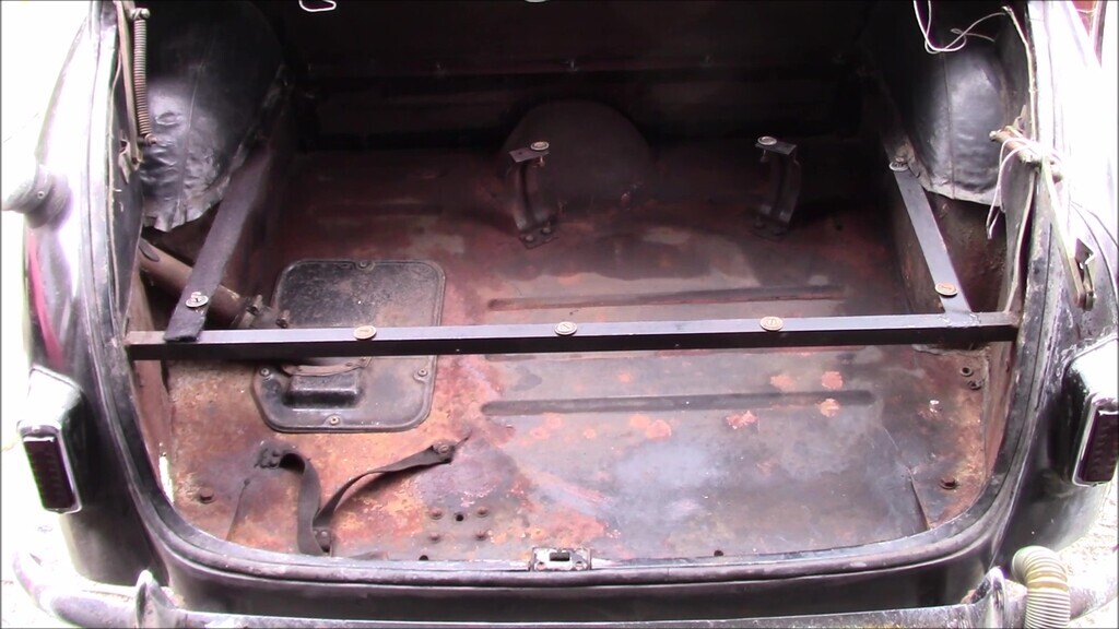
The intermediate floor is held in by quite a crude angle iron frame that's welded to the car body. I'm pretty certain this isn't a modification, I've seen plenty of cars of this era with the same sort of boot floor, I've just never seen the underlying structure. The welding is not pretty, but then I get the impression with cars like these that what isn't seen doesn't matter, rather like a glorified kit car.
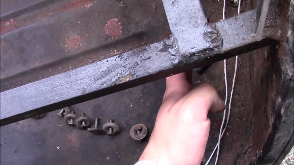
I did find some suitable screws for the fuel tank cover plates. These were a perfect fit on the thread length and pitch, and even on the button heads, and while crossheads probably aren't 'correct', they do the job. They came from the spare door latches for the Princess.
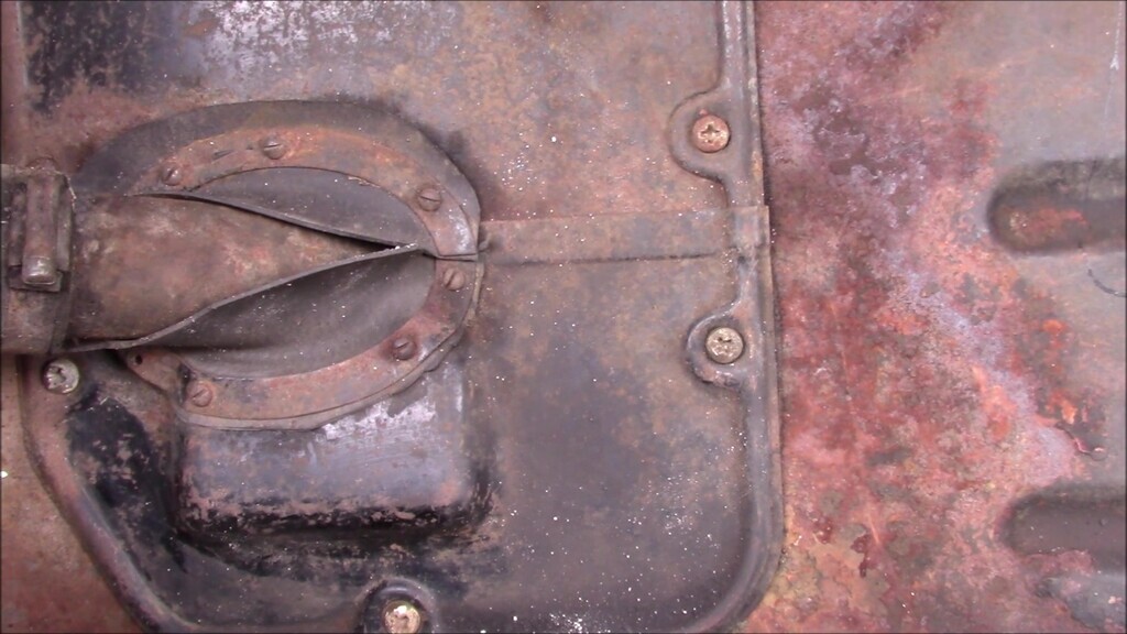
Then the floor could be tidied and more closely inspected. Happily, all the areas we couldn't see before are really solid. Aside from paint being worn away and effectively flash rusting there's absolutely nothing of concern back here. Everything will be cleaned back, giving some rust treater, and then painted with some black enamel to keep it good before the boot area is reassembled in the future.
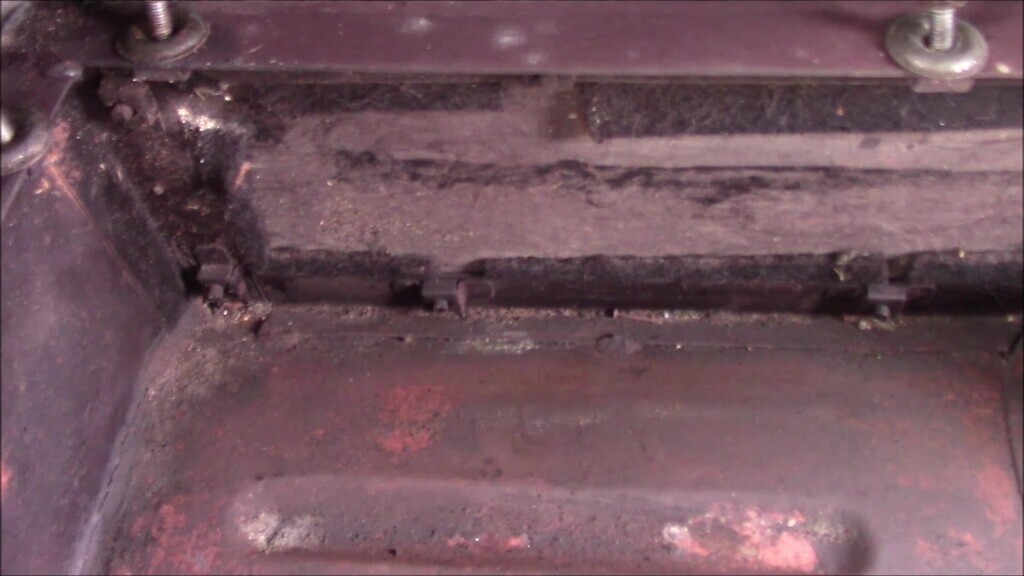
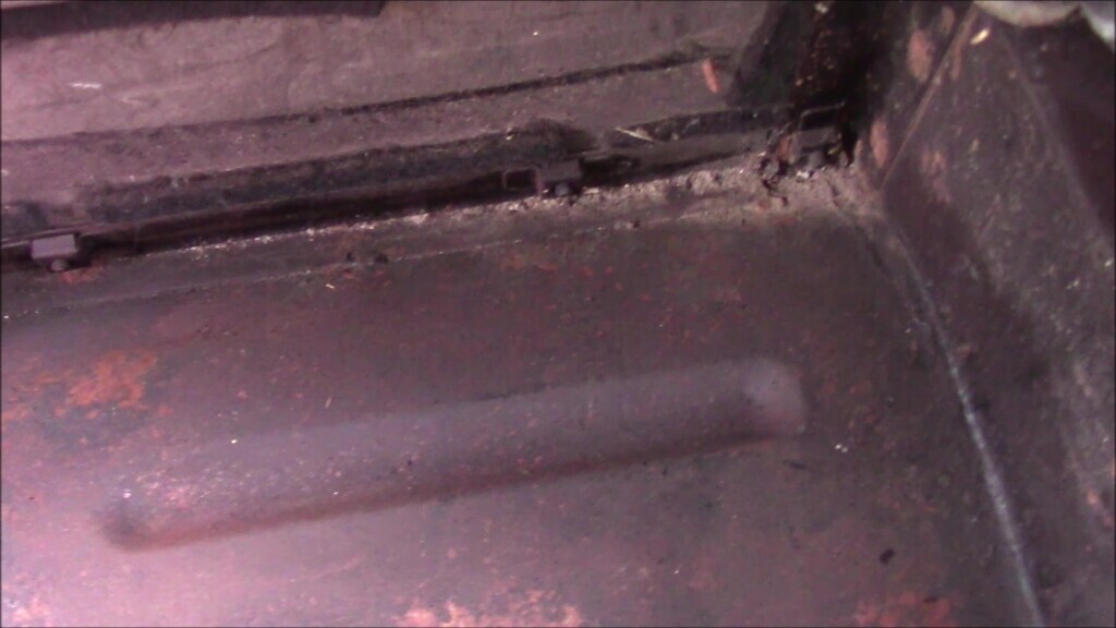
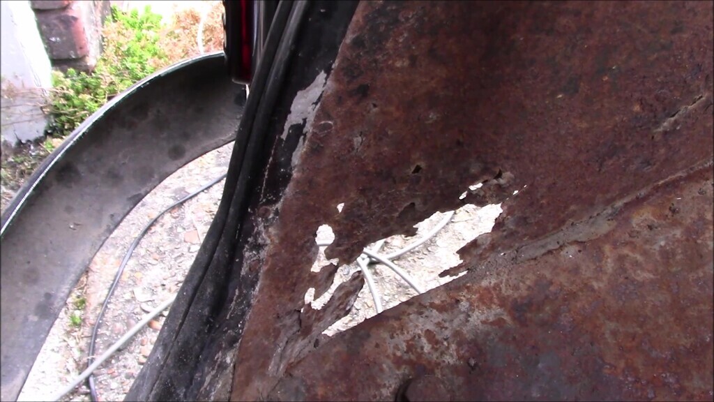
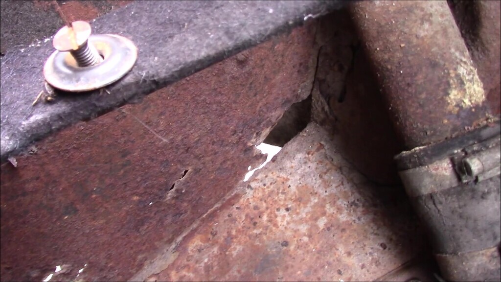
Daylight could also be shone on the areas of concern Pat and I did know about. Really, these are the worst bits (that we know of) on the car and because of how simple the shapes are and how good the access is, they held no concerns for me when it comes to repairing them. In the future I shall chop out the rot, weld in (or possibly panel adhesive in) some fresh steel and this will all be sorted. It's far enough away from the wooden framework to not cause me any concern and the steel is substantial enough on this car that I can't see it giving me too much grief. I've welded a BX, so this should be no bother.
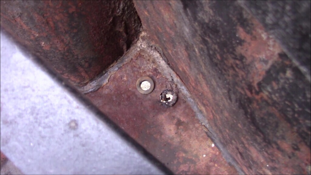
Then the momentous occasion of fitting the very first section of brand new wiring. Now, I will point out that when I did this job my welder was not working, otherwise I would have done the welding first. I opted to fit this piece because it's very easy to remove if I have to and should give a really good morale boost given that it should be a nice easy item to complete.
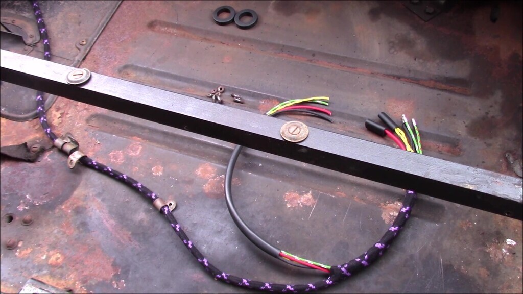
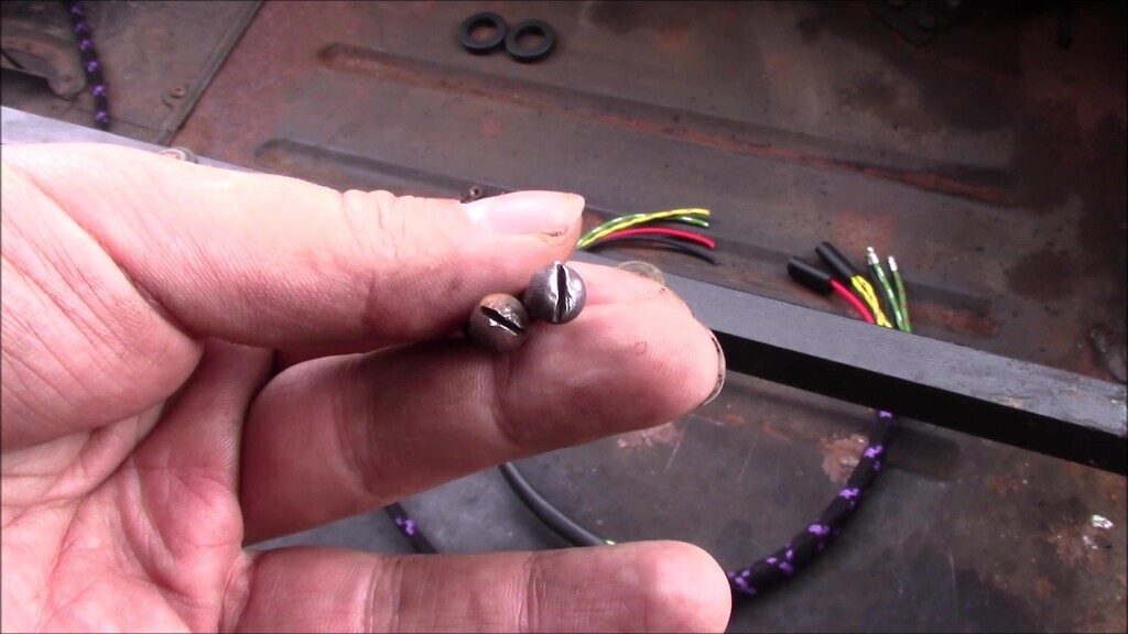
I spent a little bit of time with a file tidying up the screws that hold the P clips in place, a couple of the slots had got a little chipped when removing them.
I then checked what grommets had been provided with the loom and found out there were only two very large ones. I'd later learn these were for the bulkhead. No grommets are provided to replace the four required in the boot. This was one of the items that really annoyed me with this loom, they're so cheap it would have been nice just to have had a couple provided as a courtesy. Instead, I had to go and get some since I had none in that were suitable.
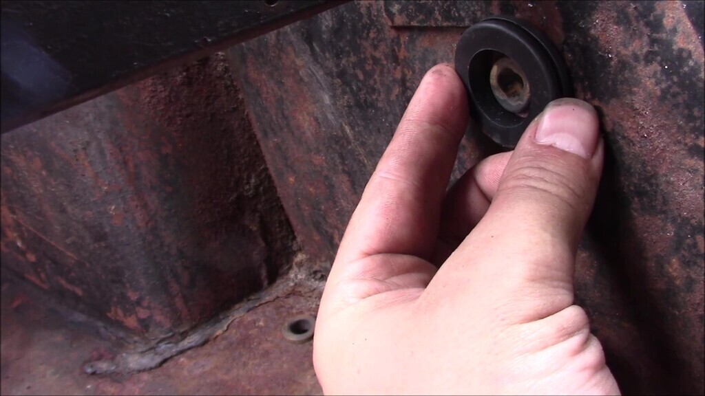
Then it was just a case of offering up the P clip behind the angle iron frame after threading them onto the wire, push the bolt through from the bumper side, and screw the nut on from the boot side. Took no time at all to get this section installed.
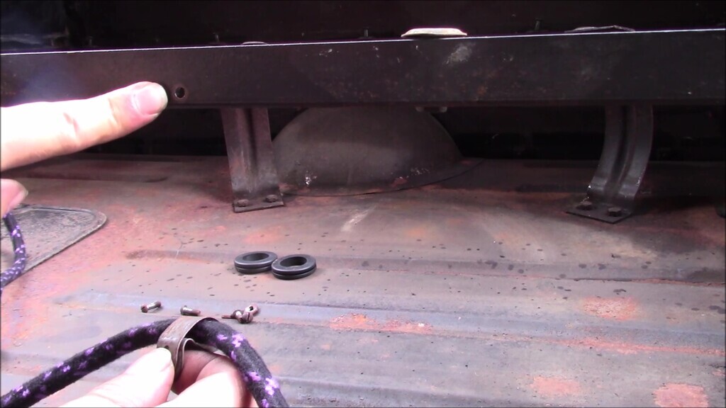
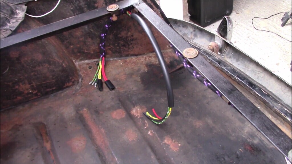
Pat was then free to help with the interior wiring instalation. Initially I attempted the sensible thing of carefully pulling the new wiring through with the strings I'd carefully run when removing the old wiring. It was tough going, the new loom didn't want to go through that easily, and then one of the strings broke. It took a while before Pat and I finally figured out that the new loom won't actually pass through the guide holes in the frame of the car in the same way the old wiring came out. I'll explain why that is later in this post. What we ended up having to do instead was install the wiring in the cabin in a very strange way.
You have to start in the middle. The hole for the original wiring in the headlining needed to be opened out a bit, then the wiring for the passenger side semaphore could be fed through first, blindly finding the guide holes in the frame, until you reach the metal section just behind and above the B pillar. There's a hole that runs diagonally down and forwards through the wooden frame that allows the wires to then emerge above the semaphore.
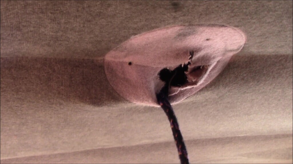
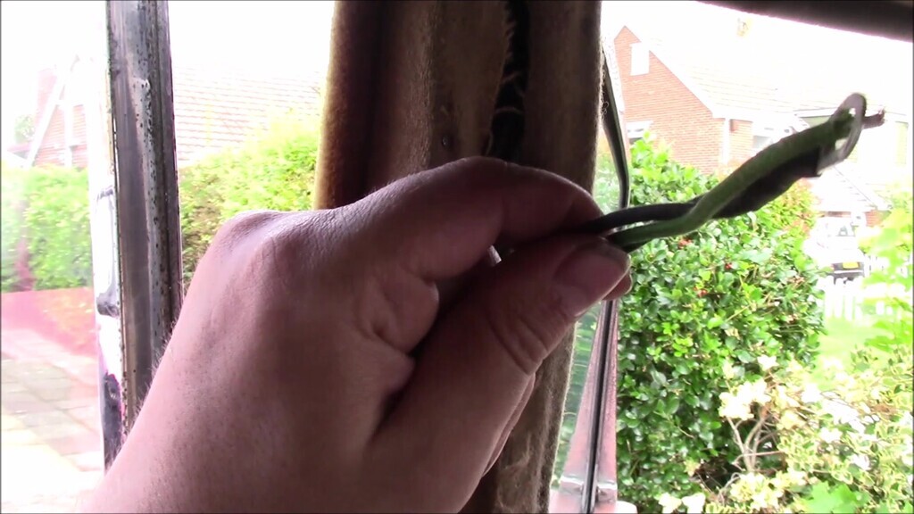
You then have to feed the entire rest of the loom that runs all the way into the boot, through the small hole where the interior light lives. This is a chore. One spur will follow the same sort of route to the semaphore on the driver's side as it did on the passenger's side. The other long run then has to be fed through the guide holes in the roof frame, which is metal, all the way over the top of the rear door and behind the trim panel alongside the rear seat. Pat did this, I'd lost my patience with burning my hand on the roof (it was a very hot day when we did this job).
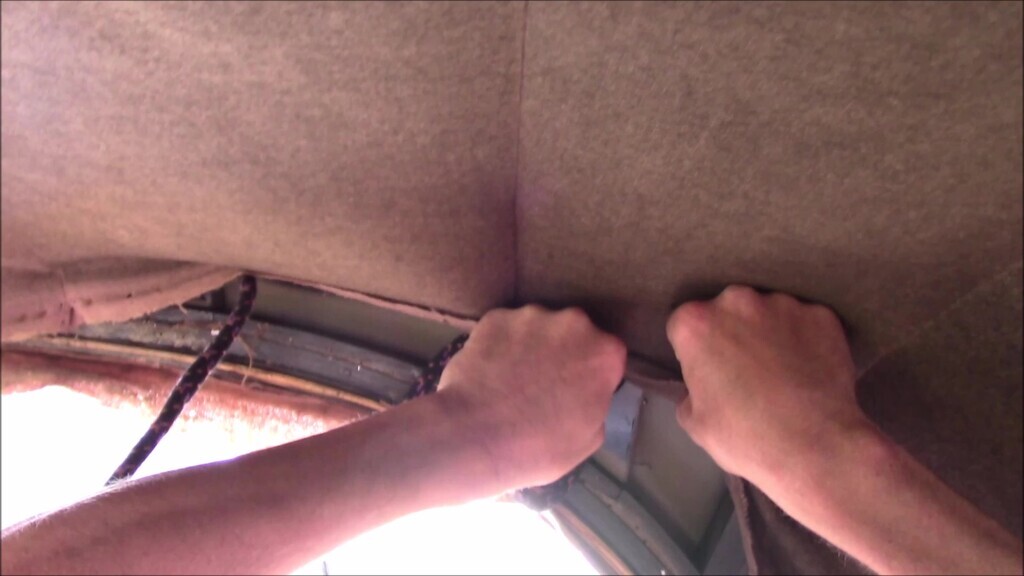
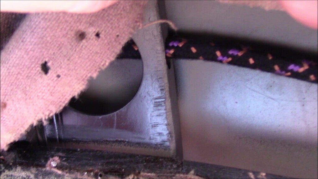
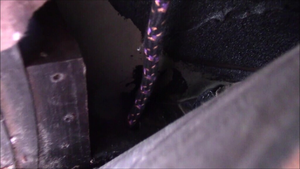
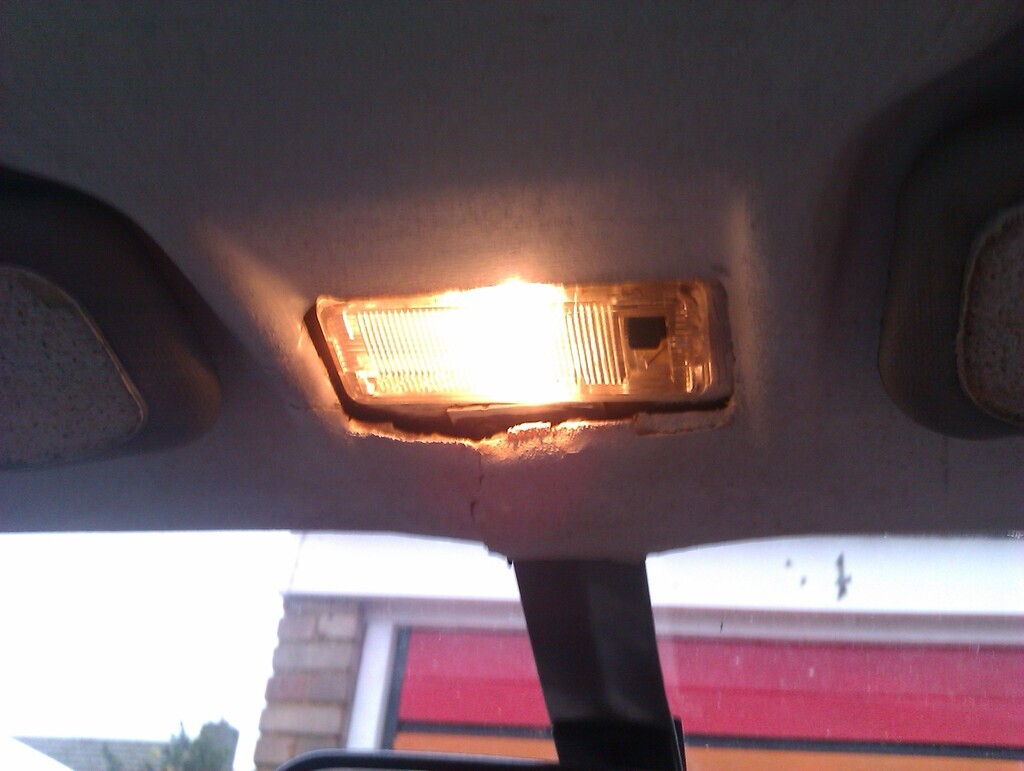
Feeding the section down through the gap between the body and the seat was very difficult, it took us a very long time. It would definitely have been easier to do this with the seat, headlining, and trim removed. However, since we want to keep as much of the original materials as possible, removing the headlining was too risky. If we damaged it we would likely have to replace the whole thing and while I have the skill to do that, it was something we wanted to avoid. This was the price we paid for that. With all of that run, I treated myself to installing the cleaned interior light (more on that in a future update), ready to be wired up later.
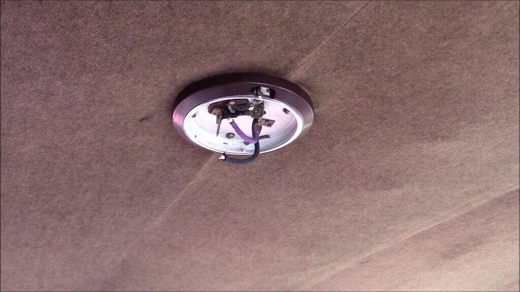
Getting the wiring through the tiny gap and guide hole in the frame hidden down the side of the seat took Pat and I more time than we care to think about. It was a deeply unpleasant job. Once done, the wiring then just needs to be run behind the millboard trim that the side hinges bolt into and it's done.
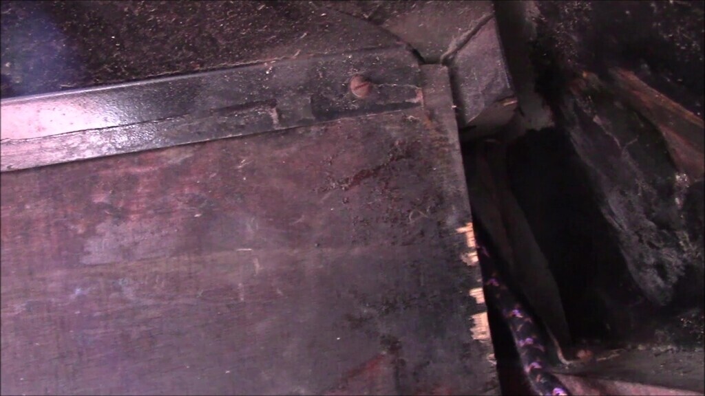
Amazingly, the headlining didn't stretch or tear, it's remarkably robust despite appearances. That meant I could tack it back into place using the same fine tacks Pat and I used when putting the door cards back together. It felt a bit weird nailing interior into the wooden frame of the car, but that's how it was done so that's how we're redoing it. There's another trim that goes over the top of this that needs longer tacks, a job for another update.
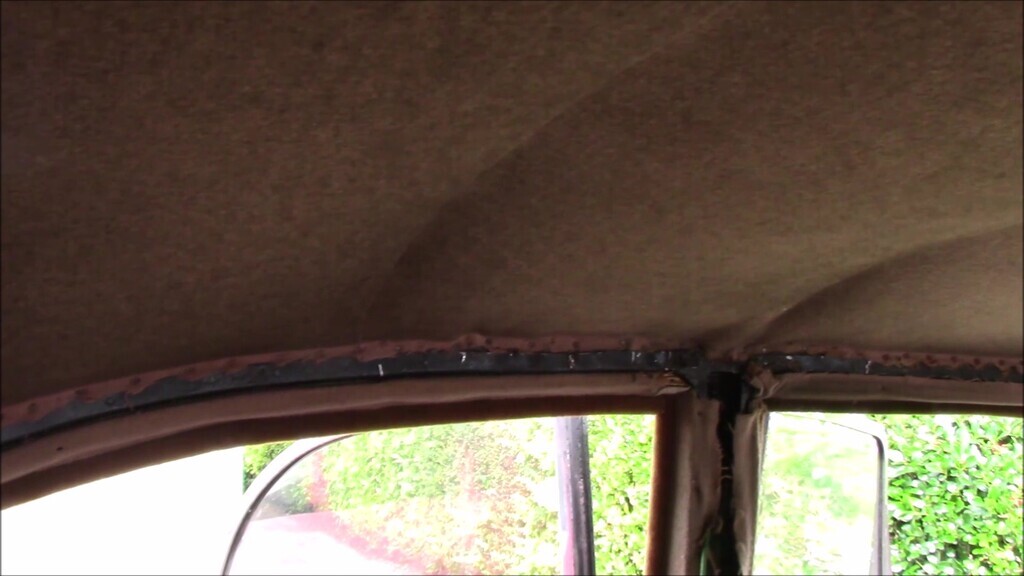
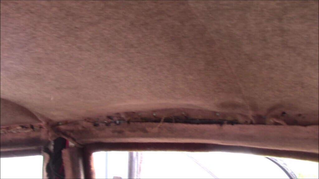
So why was it so hard to run the wiring? This is down to the new loom itself. The original wiring is constructed so that it's the wire, a cloth braid, and then a varnish of some sort to act as insulation. The new wiring is the wire, a plastic coating, and then a decorative braid. As a result, the new wiring ends up fractionally thicker for each wire. That's not a problem until you get to the junctions and spurs where the wire is wrapped. The new wiring is less flexible and bulkier and because the decorative braid is raw, it grabs the wooden parts of the frame that it goes through where the old varnished wiring would slide smoothly. As a result, you can't pass sections of the new wiring through the old guide holes without opening them up a bit, something that's easy enough to do if the car is stripped down to bare bones, but impossible when you're working around interior trim as we are. It's another courtesy item that would have been nice to be warned of with the kit since it does mean this new wiring isn't actually OEM replacement. I shouldn't have to modify the structure of my car to fit something that's supposed to be like-for-like.
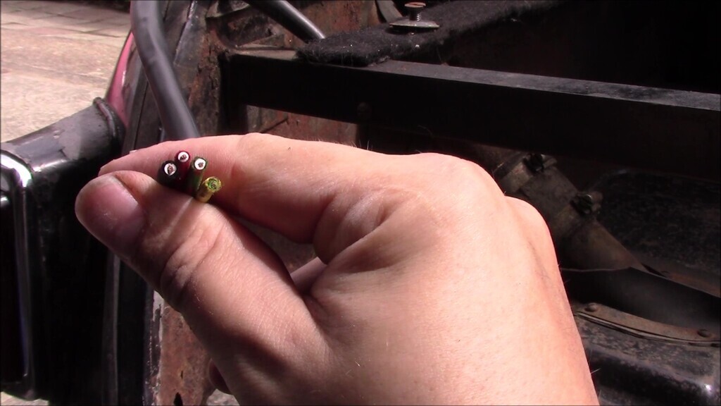
Speaking of like-for-like replacement that isn't, no spare bullet connectors are provided, that's something you have to buy extra. At least one bullet connector has become partially detached during the process of installation and in a couple of places there aren't bullet connectors where there should be. The semaphores require one bullet connector each that isn't there, and the rear lights are the same. While the three connections on the rear lights only require one bullet connector, it seems remiss that it isn't on the loom. I didn't have any in stock, couldn't order any for the same day, so I didn't get the rear lights connected up, sadly.
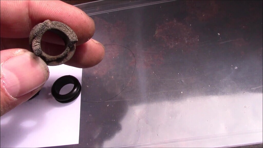
What I could do was install the new grommets I bought in an actual shop (the novelty) so at least the wiring could be kept nice and safe, ready to be connected properly later. The old grommets were pretty dead.
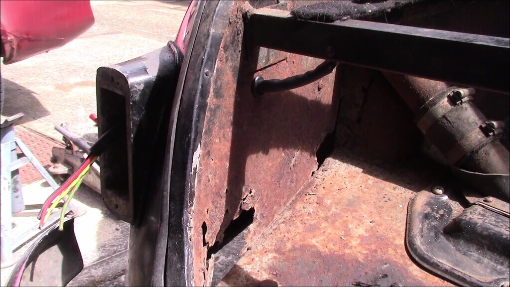
So far our experience with the re-wiring has not been a fun one. I'm very glad we didn't also decide to make the wiring ourselves, it would have been a nightmare. The loom we bought is very nice, it's just annoying that there's a lack of practical courtesy with a few small items included like various grommets and spare connectors, especially for the price. The total lack of any labelling on the components is also annoying. Some of this is because it's the first time Pat and I have tackled a job like this, some of it is because it seems to be industry standard to cut these corners. Personally, I'd like to see the company do better, especially since they're selling to the DIY market as well as to the restoration trade.


