goldnrust
West Midlands
Minimalist
Posts: 1,880
|
|
Feb 13, 2014 21:41:37 GMT
|
|
Eek thats a shame to see that rust coming through.
I think i was probably a bit blasé about getting filler wet because this will be the 4th time I've done filler work and sprayed panels, and the first time I've not done it on the driveway in all weathers! My mums mx5 spent weeks in different stages of filler outside and 18 months later the paint looks fine, I just made sure it was very dry through before I did the painting. But that was late spring, so it probably rained, then had chance to dry out properly before the next rainy day.
Anyway, decision made now, the Lancia is staying tucked away now till the paint's finished and I'm going to try and change some suspension bushes and get the Megasquirt set-up running the ignition side at least, maybe even get the fuel injections set-up too, before she hits the road again.
So the next big decision is whether I get put on my girlfriends KA as a named driver (sensible cheaper option) or look for a suitably eccentric daily to run for a couple of months? (fun option!)
|
| |
|
|
|
|
|
|
|
Feb 13, 2014 21:53:39 GMT
|
look for a suitably eccentric daily Not much of a question as you answered it yourself! Good to see it being sorted properly but please keep the momentum going you have had so far. John |
| |
|
|
bortaf
Posted a lot

Posts: 4,549
|
|
Feb 13, 2014 22:08:53 GMT
|
Kudos to you on the filling front  i hate filler and filler hates me, i have just never got the knack of reproducing the rest of the pannel lines, i'm a boss eyed, lump hammer weilding caveman  |
| |
R.I.P photobucket
|
|
|
|
|
Feb 14, 2014 11:59:06 GMT
|
currently reaping the "benefits" of driving my white astra round last year in various stages of primer and filler. rust bubbles coming through on what was clean brand new metal, complete waste of all my efforts  couple of them have now popped with rust coming through |
| |
|
|
|
|
|
|
|
|
Gooday Mate, greetings from sunny Townsville, North Queensland Australia.
I have been reading your thread for about 5 months and I am amazed at your abilities AND your stamina. To give you credit after reading your thread I revitalised my desire for a Lancia Fulvia HF, and unbelievably lucked on a Fulvia Coupe 1.3s and purchased it from Melbourne (some 2500km south) and had it freighted up sight unseen!! It was my dream after all. but considering I have owned some 40 odd cars and bikes, I have never bought anything off photos before. I would like to post some photos but I'm flat out posting this.
Had it roadworthy'd this week and club rego for Queensland. And now I commence my project of creating a replica of the Blue HF in your thread, the one with the black bonnet and bootlid.
My main priorities are the brakes, exhaust and suspension, basically replacing the lot.
To cut to the chase I would like to put Campagnolo or Coromodora rims on, however they are VERY expensive, about 1500 Euros each landed in Oz without duty. I have found Minilites here in Oz at about 25% of the cost each. I am contemplating getting 15 x 7 in gold with Toyo A888 50 tyres, however I need some confirmation on the wheel dimensions for the Fulvia 1.3s.
Best I have is PCD 4 x 130, Offset +49mm Backspace 122mm. Can you assist in confirming or correcting these measurements.
As soon as I get the hang of this I'll try to put some "on arrival" photos on.
Oh forgot to say the Lancia joins the Ducati Multistrada 1000 in the garage.
Cheers
Chris
|
| |
|
|
goldnrust
West Midlands
Minimalist
Posts: 1,880
|
|
Feb 16, 2014 10:56:22 GMT
|
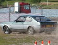
Hi Chris, I'm glad reading my ramblings has helped rekindle your Lancia desires  This will help you with posting pictures, retrorides.proboards.com/thread/34126 . It sounds like you'll be doing an interesting build, you should start a thread about it As for wheels, it is such a shame the wheels are so expensive isn't it. 4x130PCD is correct, with a 70mm centre bore which is quite large. My Cromodoras are 14x6" with a +23mm offset. Running them with 175/70/14 tyres at stock ride height I had no problems, just the odd light tyre scuff over large bumps, but as soon as I lowered the car it became obvious they were essentially too wide. With the arch lips rolled, the otherwise stock front arches clear no problem now. The rear arches as still fighting me, I've had to modify the inner arches quite a lot, stretching them out, to make room for the tyres to tuck into the arches over large bumps. If you did go for 7" wide wheels and wanted to keep the stock arches I think you'd get away with it if you had an offset around 35-40mm and you used relatively narrow 175 or 185 width tyres. Alternatively if you're going to be running wide arches, like that blue rally car, then I can tell you that it is using 14x7" wheels with a 0mm offset. It looks like it could fit even wider ones under those arches, though probably at the expense of steering feel. Here I did a photoshop of 14" wheels Vs 15" wheels and I think 14" looks better in the Fulvia arches, so that's come thing to consider. I'm very happy to be proved wrong though! Gotta love a nice Ducati also Somehow the idea of the sort of person who enjoys the quirks and eccentricity of a Lancia riding a GSXR or whatever doesn't match does it! I've had a 748 and a Monster and they both were really special, I think if Ducati made 2 strokes I'd still be riding one. I love my 2 stroke though, there's nothing like the feeling when it comes on the pipe properly. The suns shining so I might just have to go and take my Gas Gas out shortly! It was a hoot out on the dirty half flooded roads the other day, took the supermoto wheels off and put the knobbliest back on and its in it's element!  |
| |
Last Edit: Feb 16, 2014 11:10:10 GMT by goldnrust
|
|
goldnrust
West Midlands
Minimalist
Posts: 1,880
|
|
Feb 16, 2014 11:22:32 GMT
|
While I'm sat at the computer I might as well add a small update to the Lancia's progress. Hours and hours of sanding later and I'm getting pretty happy with the shape of the right front wing. I think it's a lot closer to finished than the other side is, so I will have to revisit that at some stage.  So for now I'm moving on to the right rear. As I referenced in the last post and as pictured a few pages back, I've had a number of issues with the rear tyres scrubbing the arches. With a hard roll and some stretching of the inner arch shape the left rear is now clearing the tyre fine, but I still get occasional scrub from the right rear. I've even stretched the wing out slightly in my attempts to make enough room for it to clear. In order that I get both rear arches the same ( lesson learnt from the froth arches last year…) I took some measurements from the left rear and transferred the overt the right, before I started any of the final panel beating and the skim of filler. The good news is the arches are the same shape, but interestingly I've pulled the right one out to 5-6mm wider than the left (with reference to the axel position so not a pan hard rod adjustment issue), so it's odd that this is still the side thats scrubbing. This made me think the axle must have some extra lateral movement with some worn components? So I took the rear springs out to investigate and yes there's definitely problems…. Both rear leaf spring eye bushes are shot, in the right one the crush tube has fully detached from the rubber   Not only that but the shackle bolt has stretched so even with the nut done up tight, it doesn't hold the shackle tight to it's bush. The shackle is heavily worn with the bolt hole stretched. And too add insult to injury that right shackle bolt is seized in place….  Oh good…. Anyway, I best order some new bushes and some new shackles (or make some cost depending?)! |
| |
|
|
eurogranada
Europe
To tinker or not to tinker, that is the question...
Posts: 2,552
|
|
Feb 17, 2014 10:00:24 GMT
|
|
You'll not be short of work for a while yet! (like me...)
|
| |
|
|
goldnrust
West Midlands
Minimalist
Posts: 1,880
|
|
Feb 18, 2014 14:37:30 GMT
|
I think you're right there mate! As my birthday has now been and gone I'm finally allowed to play with the Megasquirt I made a start on building the broad last night, with some help from my girlfriend reading me the instructions (and taking photos…)  The first step is to build the voltage regulator and rs232 COM port components, and then test them. The instructions tell you to do this by using a specially configured hyperterminal file to send keyboard strokes down through the COM port, then using a jumper on the board loop it back to the computer. Basically if when you type it comes up on the screen then the COM port stuff is all working.  Yup that looks good. So next up after that is to build the clock circuit for the processor and voltage sensing circuit. With that complete the next step is to fit the processor.  Then the moment of truth of firing it up and loading the firmware.  Which all went smoothly. So now I have a processor that has firmware loaded on it, which can communicate with the computer. The next step is to start assembling the circuits that allow it to take readings from the engines sensors and relay them to the processor. |
| |
|
|
|
|
|
Feb 18, 2014 20:57:36 GMT
|
|
Belated happy birthday mate!
|
| |
Koos
|
|
goldnrust
West Midlands
Minimalist
Posts: 1,880
|
|
Feb 19, 2014 11:48:25 GMT
|
Cheers mate Did some more Megasquirt building last night. The input conditioning circuitry is now all complete.  And with it hooked up to the computer it all works I have tach, MAP, TPS, coolant temp, IAT and oxygen sensor readings all reading correctly.  It was, however, not as plain sailing as it sounds. I experienced the negative side of Megasquirt. As it is very open source, and developed independently, theres a numerous guides to follow and they don't always agree with each other…. I had started building my tach input circuitry with the opto isolator, following the main Megamanual guide for using a hall type crank sensor. But then cross checking with the MSextra guides, which are more regularly updated, and it's suggested that for a hall sensor they've had better results using the VR sensor input as there can be a time lag using the opto isolator. It wasn't a big deal, just meant I had to swap a couple of jumpers over and I'd put a few components on the board that be spare now. To complicate matters when I came to test the tach circuit I couldn't get an RPM signal. After much head scratching and checking of components and cross referencing circuit diagrams I realised my mistake. I'm re-using my old Megasquirt stimulator board, which simulates various engine sensors for testing purposes, but I'd previously modified it to simulate the crank signals from the Rx7, I'd not undone those modifications. Once I put the stimulator back to standard, I got the tach working. It's all part of the experience I guess. Anyway it's all sorted now, which just eaves the output circuitry to build; the coil drivers, injector drivers, relay outputs, etc. Hopefully another couple of hours this evening and the main board will be done, and I can start looming it into the car. |
| |
|
|
|
|
|
Feb 19, 2014 18:32:12 GMT
|
|
I know what you mean about the online MS instruction manuals, so many different versions out there now, gets confusing.
Look forward to seeing this all come together. Will you go with bike throttle bodies or a homemade injector manifold?
|
| |
|
|
|
|
|
Feb 19, 2014 18:52:33 GMT
|
|
Yeah I found that too. Too much info out there and all over the place with much of it ever so slightly conflicting. I ended up following the extra manual. I figure that once ytou have built a few, as you have steve, it gets much quicker.
Both Hannah and I really enjoyed the build process and I'm looking forwards to building another one. Just need to get a car to squirt...
|
| |
|
|
duncanmartin
Club Retro Rides Member
Out of retro ownership
Posts: 1,320
Club RR Member Number: 70
|
|
Feb 19, 2014 19:09:14 GMT
|
Cool. When's the Supercharger arriving? |
| |
|
|
goldnrust
West Midlands
Minimalist
Posts: 1,880
|
|
Feb 20, 2014 23:46:09 GMT
|
It certainly does get quicker Alex, and you know what pitfalls to watch out for . This one had been a slightly slower build because I've taken a relaxed approach to it, unlike some of my previous builds it's not a case of ' I car start the car and go for a drive as soon as I finish soldering this'. I mostly follow the V3 assembly on Megamanual, simply because it was the guide I was told to use when doing my first MS build on my mx5 turbo (all those years ago…), and then I revert back to the documentation on Msextra for the ignition input and output modifications. Regarding the supercharger plan…. plans have changed because I've been busy with the maths and I've come to a disappointing conclusion. The point of using the supercharger was essentially it being an easy route to a huge chunk of extra power. Turbo would have been my first choice but with the engine leant over like it is, there's just no room, unless I were to do a remote turbo set-up and that's just not elegant enough. So anyway supercharger, big power easy, or not as the case maybe… The engine in stock form is 90hp. Most engines will take ~0.5 bar (~8psi, working in bar makes the maths easier!) of boost with stock internals, but past that it becomes a gamble. The n/a tuned Fulvias start running into issues with crankcase flex as the power goes up, also the design of the V4 means there are only 3 main bearings and the centre main is fairly small to compound the problem. The final piece of the puzzle is that as there are only a handful of forced induction Fulvias ever built, you can't buy upgraded rods/pistons suitable for this purpose, only lightened ones for revving the engine harder n/a. All of that means basically I wouldn't want to run over 0.5 bar boost. Doing the airflow calculations that puts me right in the middle of the efficiency map for the Eaton m45, hitting the maximum efficiency island spot on, so it's all sounding fine so far. In a perfect world, 0.5 bar boost = 1.5x the amount of air and fuel of the stock engine, which in turn means 1.5x the power. 135hp would do me very nicely. But this isn't a perfect world. Even with the charger at max efficiency a considerable amount of heat will be added to the intake. If I was to run without an intercooler then with the losses due to hot (and therefore thinner) air would mean that 135hp becomes 113hp, potentially even less as this doesn't include the reduction in ignition advance needed with the hot air to avoid knock. If I could fit a decent intercooler (say 80% efficient) then we go back up to 131hp, but in order to fit the charger belt the radiator will have to be pushed into the nose of the car, which means no intercooler room. Also fitting an intercooler would require me to run a dual throttle system which complicates the intake pluming further. Forget the intercooler, and lets say that the heat doesn't cause me too many knock problems and I've got 113hp now, this is all before taking into account the HP used to drive the charger, which will be about 12hp by the redline. So lots and lots of work, adding lots of heat and stress to the engine and all to go from 90hp peak power to 100hp…… Now I'm well aware that's not the whole story, as theres likely to be significantly larger percentage midrange gains to be made. But I like small engines that scream to the redline, and I want more peak power. So basically after all that, I'm going back to the idea of an n/a build. I will run bike throttle bodies, the 38mm bodies from a cbr600rr are looking the likely candidate for now, and with the accurate fuelling and electronic ignition that will hopefully gain me a few horses to start with. A well designed air box, some careful head work and a custom exhaust manifold (the stock one is a very dated 60s design) should see me heading for 120hp, still a sizeable gain over the stock power. And after all that, if it's not enough, there's nothing to stop me investigating superchargers again at that stage!  Anyway the Megasquirt build carried on this evening.  All the components for the output circuits are installed now. Looks lovely and neat doesn't it? Another slight downside of Megasquirt is because of the way it's developed over the years, the ignition output are often a sort of after thought, and need a number of modifications wired in. It's all part of the fun I guess…. Here you can see the modifications I've made in order that the Megasquirt can drive a 4 cylinder wasted spark coil pack directly, with no external ignition amplifier unit.   And with that, it's done!   Hooking it up to the stimulator and the laptop and the LEDs flash as they should indicating that the coil drivers, injection drivers, fuel pump relay output and idle control output are all working as they should  So thats the end of the soldering for a bit, back to sanding filler and attacking stuck bushes for me. There's still plenty of soldering to do though, before the Megasquirt gets installed in the car, I need to make this lot into a loom…..  |
| |
Last Edit: Feb 20, 2014 23:52:24 GMT by goldnrust
|
|
|
|
|
|
|
|
I ate spaghetti that was almost that many different colours, once! D:
Nice to see that you've decided on a path with power (for now).
|
| |
|
|
crahel
Part of things
Posts: 210 
|
|
Feb 21, 2014 12:08:27 GMT
|
|
Id very interested in seeing what sort of HP gain you will be able to squeeze out of the motor, I am looking for more torque and I think a charger will be the only option. 0.5 bar to 0.7 bar would be my limit. I'm going to take my 1.2 lt out of storage and get working on mounting the supercharger soon. The 1,2 has stock 9:1 compression ratio so hopefully wont have to retard ignition to much to prevent knock. Have you looked at the crank case bracing that's been done to strengthen the bottom end, what's your thoughts? Do you think there is any way of making an improvement to bottom end center bearing oil starvation?
Craig
|
| |
1973 Lancia Fulvia s2 coupe (sold)
1998 Audi a4 sedan (sold)
2000 Nissan maxima (sold)
2007 Audi convertible.
|
|
smeden
Part of things
"Full throttle until you see God,then shift to second"
Posts: 356
|
|
Feb 21, 2014 12:47:35 GMT
|
|
I envy you skills with the iron! I could never build a MS.. Following this!
Will you be using a tps mounted on the itb's and what about the TDC? trigger Wheel or the dissy?
|
| |
Jaguar xj6 S1 swb manual
VW Bay Camper
Audi A3 1998 1.8
VW Beach Buggy (sold)
Ford Mondeo mrk I RS Celebration (written off)
Ford Escort Mrk II RS 2000 (rust in peace)
|
|
goldnrust
West Midlands
Minimalist
Posts: 1,880
|
|
Feb 21, 2014 17:37:09 GMT
|
I'll be interested to see the power too Craig! If you want that extra chunk of mid range torque, then yeah n/a tuning is never going to offer that. I suspect you'll need a fair amount of ignition retard, regardless of the compression ratio, just because of the heat generated by the charger. But hopefully you'll make the midrange power you need I'm quite happy with the the Fulvia drives around day to day on it's stock power, its when I stick my foot to the floor and redline it that I want more, and the maths suggests the supercharger wont help me there as much as I'd hoped. The radiator positioning seemed to be the biggest issue for charger position for me, it sits very close to the front of the engine currently, no room to put a wider front pulley on for a 4/6 rib charger belt. I've not investigated any of the Fulvia specific crank case strengthening, aside from knowing it's generally in the form of a ladder brace though the bearing caps. Realistically, when it comes to forced induction and fuel injection stuff I've got enough real world experience to back up the books I've read. I've done bottom end work on a number of 2 strokes, but I'm completely fresh to 4 stroke bottom end. Anything I could tell you would only be based on books. For now the bottom end isn't the limiting factor for my engine making power, so it's not at the top of my priorities, I'm sure at some stage in the future I'll need to investigate it. There's some good chatter about the crank case braces here: var1016.blogspot.co.uk/2010/07/email-exchanges.htmlBeing tidy with a soldering iron on a circuit board is quite different to doing normal loom stuff, Smeden. With a bit of practice anyone can build a Megasquirt Most bike ITBs have a good tps built in, so yes I will be using that. With the 35mm carbs the engine already doesn't draw much vacuum, so I'll be mapping with the Alpha-N algorithm (TPS vs RPM). I'm using a hall effect type crank sensor with a 36-1 trigger wheel mounted to the front pulley, with a wasted spark coil pack so should be able to remove the dizzy entirely. |
| |
Last Edit: Feb 21, 2014 17:37:29 GMT by goldnrust
|
|
|
|
|
Feb 21, 2014 19:26:01 GMT
|
|
would've thought crank flex would be more centrifugal/inertial from higher rpm (n/a tuning), than torsional/radial from high cylinder pressures (forced induction) ? don't know this specific engine of course.
|
| |
Last Edit: Feb 21, 2014 19:27:12 GMT by darrenh
|
|


 This will help you with posting pictures,