eurogranada
Europe
To tinker or not to tinker, that is the question...
Posts: 2,555
|
|
|
|
Oh no! Reading back, it seems the damage occurred as you were cranking the engine. Have you checked the earth strap between body and engine? If loose / damaged / high resistance you'll get weird ground currents through any other available path. Usually a clutch cable or something, but still a good thing to check in your quest for the smoking gun. Good luck. Yes, I've checked the earth straps and ground cable to the battery. The battery to engine lead was tight and the engine to body strap was tight as well. They were however attached at the same stud on the engine. Something I feel I should change this time around. I'll be sourcing a new ground lead as well as there is some sign of chafing on it. However at those points (or anywhere really) there's no sign of shorting. I will also pay closer attention to any paint around ground points.I usually clean away the paint at those points, but I found one or two smaller ground connections that were maybe overlooked around the headlight area. Which is also where the fans that didn't come on on the last drive are grounded. |
| |
|
|
|
|
|
|
|
|
|
Feel for you Alex, just work through it methodically and don't rush or cut corners (easy said I know  ) |
| |
|
|
eurogranada
Europe
To tinker or not to tinker, that is the question...
Posts: 2,555
|
|
|
|
It's probably worth fitting a kill switch in the battery feed to avoid potential future issues. I had a wire short out in one of my cars once for the (unfused) headlamp circuit - massive smoke in seconds - ripped (literally) the headlamp switch out of the dash to stop it. Wires looked exactly like yours with the same damage to wires around it. I'm really in two minds about these kill switches. Obviously I understand the advantages breaking the power flow fully when the car is not in use or being able to quickly kill power flow in the event of a short like I encountered. Really I do... But to me there's also the other side. A side of convenience and necessity. My car now has an ECU, without a constant power it would enter it's learning stage each and every time as after 15 minutes of being powerless it forgets what it has learned. Same for the stereo installation. I have a head unit I'm still in love with after 15+ years. But this too needs setting up withc custom settings. So again a continueous power needed. I'd hate to go through the setup of that thing each and every time... Point being, in a car one can't just cut all power without sacrificing usuability/convenience. And if the answer to this is to just run those two (possible some more) power feeds as a bypass, then is there still merrit in installing the kill switch? If anything my recent meltdown proved that power will find any possible route. Then there's the point of the location. I think I saw someone install one under the bonnet of their car a while back. Well, is that a location one can get to quickly? So where do you put one? In the wheel well would be out of sight and relatively accessible. But this also means longer power leads that need to go through or around crossmembers increasing risks as well. Same for fitting one inside the car. Add to that they are bulky and ugly by design. Also, but I admit this is hard to judge, I feel that like any part of the car wiring should be kept in good condition and checked. And I thought mine was and I had. During the restoration of my car the full loom was examined. My original wiring is not chopped about in general, the looms were nicely packed, connectors all looked good etc. Wires were flexible enough for their age. The additional items wired up were wired up with new wiring. And the added BOB loom was gone through and measured for resistance and continuity. And checked out fine. I had no real reason to doubt anything and therefore no reason to mount a kill switch. Now one could say that my experience should prove that kill switches have benefits, and I'm considering adding one, but I just haven't gotten my head around it yet given the above. |
| |
|
|
MaxN
Part of things
 
Posts: 482
|
|
|
|
|
I get the idea of a kill switch, but most modern cars have a fuse link to the battery, within the battery cable. Suddenly start growing huge power and it blows. Super safe and while a bit of a pain to replace it, it adds a ton of peace of mind. You can even get the fuse link as part of the battery ter,I also for very few $$s
My fathers old XR3 had an electrical issue that was eventually traced to a brake light bulb manufacturers fault. Long story story when you hit the brakes the cable was shorting slightly and intermittently blowing a fuse.
We also found that if you put your foot on the brakes you could take the key out, with all of the power flowing through that light cluster. If you hit the electric window switch the fuse would blow.
Once we found that, we discovered a fair bit of wiring damage in the loom that went to the back of the car. From memory the loom was not modular, so we spliced and soldered in quite a few new lengths.
Unfortunately he wrote the car off on a notorious bend one rainy night shortly after, so the long term viability of the repair was never tested.
In your cases. I’d be lokk8ng at a fuselink for the battery to save future issues, but probably also looking for a better loom for the nonBob section of the car. It surely cannot be that complex due to the lack of tick at the time.
|
| |
|
|
|
|
|
|
|
|
Trouble is a battery fuse link is typically 800A if it takes the all the load or around 100A if it takes all but the , engine cranking, many of the other wires within the car will melt long before the fuse blows. Earths can be a particular problem, so you have a cable rated for perhaps 20A which is more than enough for the intended loads, at a body earth point you have several earths which perhaps total a peak of 50A, if the earth to body fails and one earth is also earthed through another path (like the body of the ECM) then all the load for all the earths goes through the 20A cable and after a while you have meltdown. As mentioned above poor engine earths leading to cranking loads taking another path can do the same thing as can cooling fans.
|
| |
|
|
|
|
|
Jul 20, 2022 12:23:09 GMT
|
|
The kill switch is only there for emergencies.
You could indeed run a bypass for the stereo and the ECU if you wanted but really it's only there for emergencies such as yours. Then reprogramming the stereo becomes not such an issue.
I'd fit it either inside the car where the driver can reach or near the battery. Really though, by the time you undo the bonnet & run round the car to release it it's too late.
|
| |
|
|
mk2cossie
Club Retro Rides Member
Posts: 3,047  Club RR Member Number: 77
|
|
Jul 20, 2022 12:33:03 GMT
|
Just to throw something else in to the think tank, I have a resettable fuse on my main battery positive terminal. Thats either 150 or 300amp, can't remember now. But when my electro-hydraulic steering pump went up the swanny, the fuse would trip. Saved the main power line and battery from taking a huge hit  |
| |
|
|
eurogranada
Europe
To tinker or not to tinker, that is the question...
Posts: 2,555
|
|
Jul 20, 2022 14:38:16 GMT
|
The kill switch is only there for emergencies. You could indeed run a bypass for the stereo and the ECU if you wanted but really it's only there for emergencies such as yours. Then reprogramming the stereo becomes not such an issue. I'd fit it either inside the car where the driver can reach or near the battery. Really though, by the time you undo the bonnet & run round the car to release it it's too late. In my line of thinking, the kill switch was allso used to kill power when the car is not in use. I see quite a few people use them like that, but I would not consider that practical. Like you say, if only for emergencies then it makes a lot more sense. And I'd agree it needs to be in the driver's easy reach. Unfortunately that would necessitate longer leads as the battery is on the wrong side in this case. Anyway I'll have a think about all the views expressed. Prevention/preservation is what matters. |
| |
|
|
|
|
|
Jul 20, 2022 15:17:34 GMT
|
|
You can fit the switch with a remote Bowden cable if required.
|
| |
|
|
thomfr
Part of things
  Trying to assemble the Duett again..
Posts: 687
|
|
|
|
You can fit the switch with a remote Bowden cable if required. Bike brake cables are very nice (and cheap) way to do so. Thom |
| |
73' Alfa Giulia Super
64' Volvo Duett
65' Volvo Duett
67' Volvo Amazon 123GT
09' Ford Focus 1.8
20' VW ID4
71' Benelli Motorella
65' Cyrus Speciaal
The difference between men and boys is the price of their toys
|
|
qilin
Part of things
 
Posts: 19
|
|
|
|
|
Hi
Looking at the pictures of the wiring it looks like a ground issue. The ground wire(with no insulation) which is connected to the 3 wires in your hand.
The connection is bad. Not how it should be done.
The gauge of the wire looks to small.
With those problems it is easy to overload the ground wire. Add in a poor connection to the metal of the car body and it overheats due to friction generated by the current.
Do you have a wiring diagram of your swap? I would look at the wires that are melted and find where they go. The first step would be the 3 wires connected to the melted ground. Where are the 4 wires connected? What colours?
1. melted ground wire?
2. The 3 other wires?
One wire looks like it could be the ground for the electronics so could be connected to the melted wire to the Ecu.
I am not familiar with Ford but it may be similar to DIN.
|
| |
|
|
eurogranada
Europe
To tinker or not to tinker, that is the question...
Posts: 2,555
|
|
Aug 23, 2022 13:00:25 GMT
|
Been quiet for a while. Been on vacation for a bit like many of us. I can say that it has done me good to be away from home for a few days having a lot less on my mind and just enjoying our accommodations, the all-inclusive drinks and food and most of all the pool, sea and sun. Fisrt time in 4 years that we were away as a family. Once home even though still off from work, you quickly see the difference between being home and being gone. Lots of little jobbies to do for ourselves, my daughter, my parents and my MIL etc. Also regular things like the routine of the dogs etc. meant pretty much business as usual. I had planned on getting on with the Granada loom damage, but I only got to that in the last two days. I took over the dining table and laid it all out and set up the laptop and some reference materials and set to work. 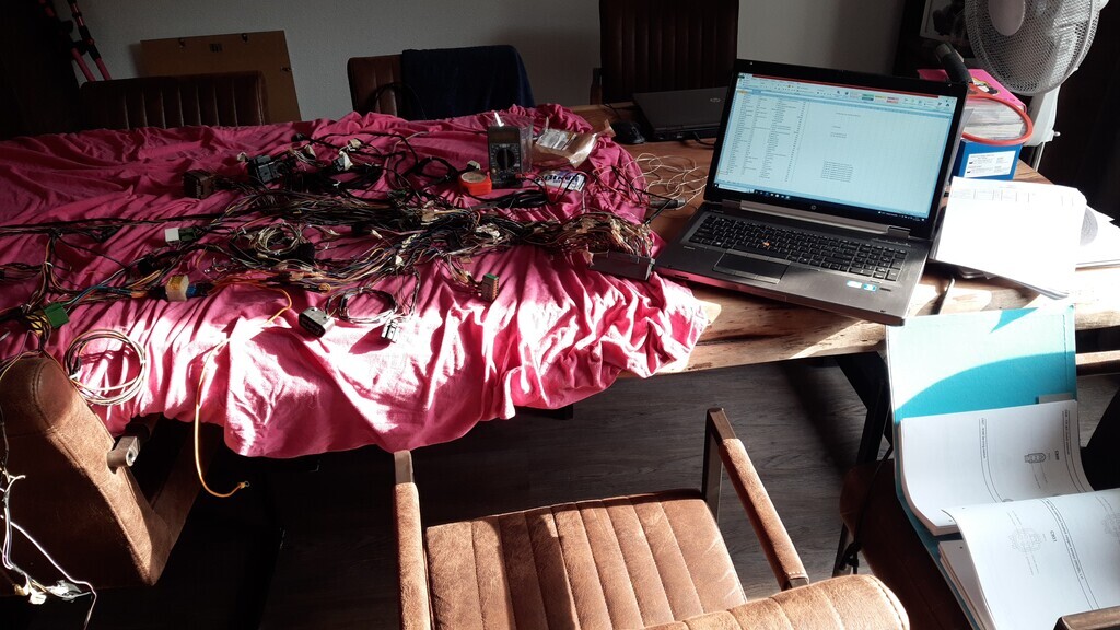 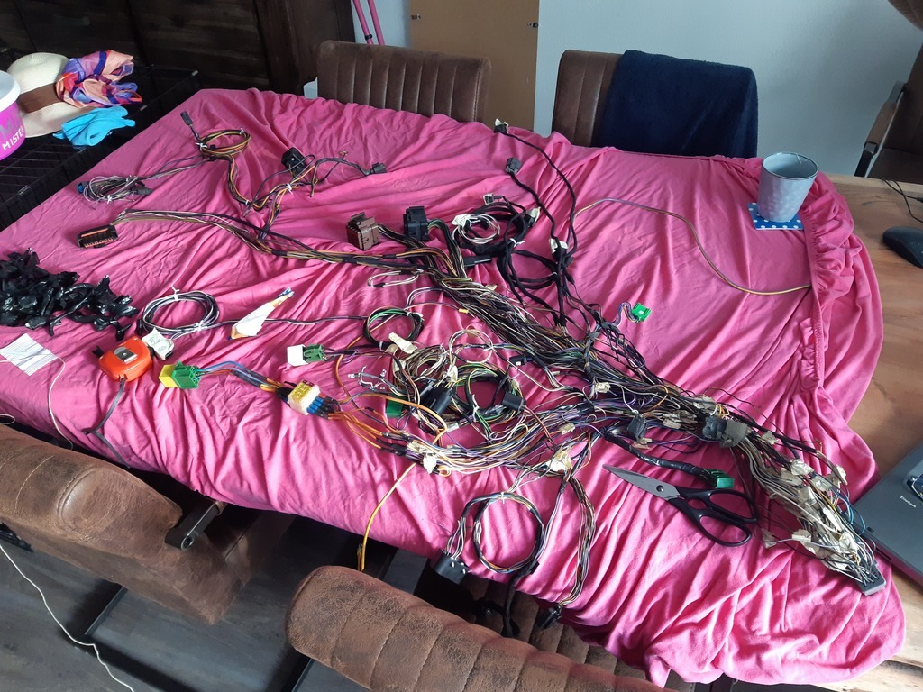 First I removed the last major bits of insulation from the main loom parts. Next I traced every wire from the ecu connector to their respective destination connectors or ground or power sources. Documented all that including wire color, length, thickness, purpose, etc. This should help rebuild and also determine what to buy new. It's now back in the garage on the workbench to get on with the next step: trace back each connector as some of their connections go to power, ground or other connectors, bus bars etc. and I don't want to forget a single wire. 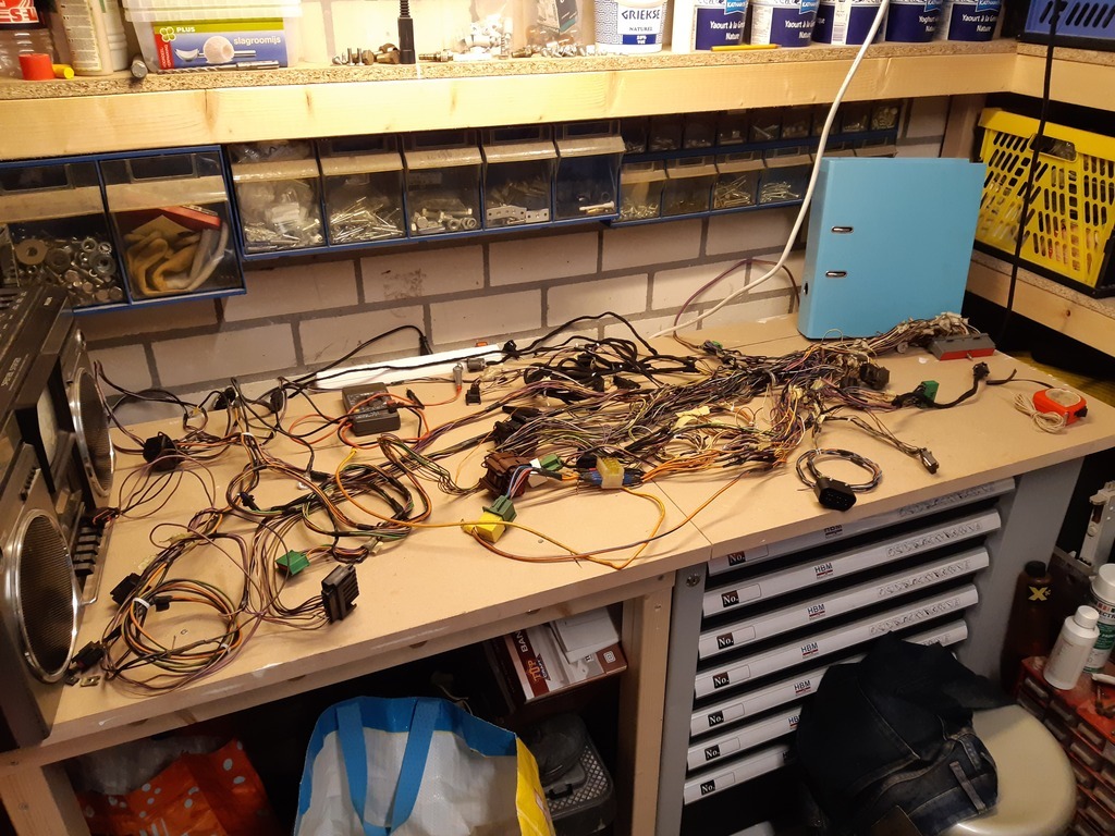 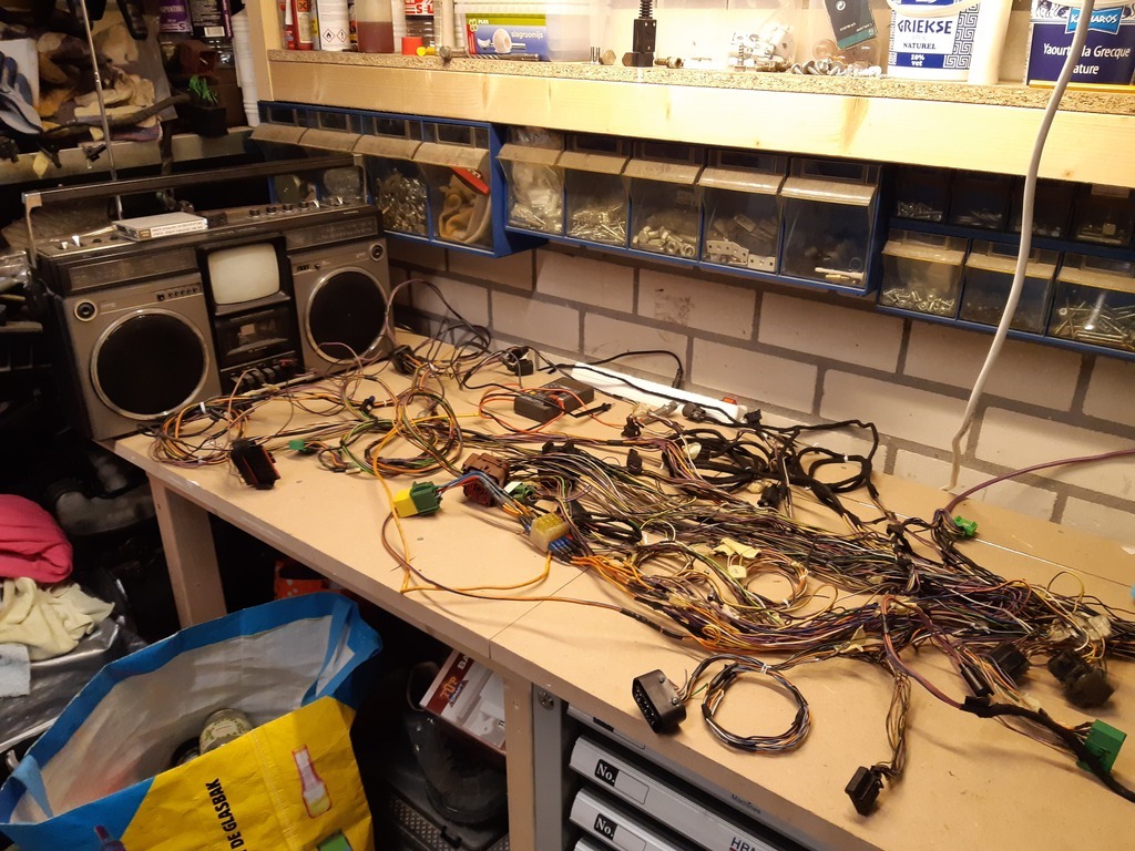 With that complete I ultimately have several more steps to go: - redesign the power system as I'm not too happy with it currently - order new wires and fusebox(es) and replace the lot - lay out the new design in the car for a more custom fit to the granada (as the original loom was built by a friend without the car present I made the components fit the loom rather than the loom fit the car) - get it all soldered - fix the little bit of damage to the original loom - decide whether to strip out and check the entire original loom (i've not yet found any other damaged wire or indications thereof, but you can't see what is under the tape. I'm contemplating fixin the broken bit and putting power to it all and testing each function) - replace the engine and gearbox loom part for a known good one, requiring removal of the air intake, fuel rail and much swearing I expect. - see if it'll run again - wrap loom after succesfull test I do have some questions though. Maybe you can advise: - how best to fix the loom? I can get a new connector but not the exact correct pins. I can maybe get a close facsimile of them at substantial cost, and would need to find a suitable crimp pliers but there's no documentation available. Also, I still won't be able to buy every connector new (or if I can I don't know where or have the budget) or find the pins for them. So I'm thinking of cutting all connectors and the main ecu connector wires a few cm after the connector and splicing in new wiring. This only leaves me with a problem on that one ground pin where there's nothing to solder to, although I think a friend can supply me this pin from a spare hacked up loom. Is this type of repair acceptable enough? I've seen plenty done this way but still. - I want to combine the three relays in one fusebox, but they have different prong layouts so I don't know if that is even possible. Can universal fuse boxes handle both direct positive feeds as well as a section that is coming from a switched positive? - I want to redesign the power system. Currently it has 5 or 6 fuses and each fuse leads to 2 or even more (5-7) wires combined and soldererd to one larger diameter wire. I'd rather see each wire with their own connection/fuse, or use bus bars after the fuse so each wire is still fused the same but has a decent connection. Most of this is switched live after one main relay, but some of this is direct live as well. If I would wind up fusing each wire, than it would seem to be quite a lot of fuses and also how do you determine the fuse value then. Now they are all 20a, but for the combined load. Seperate wires could do with lower ratings as given 20a individually I can see this being too high and therefore negate the purpose and see the wire burning before the fuse pops worst case... |
| |
|
|
|
|
|
Aug 23, 2022 14:11:32 GMT
|
|
I get the idea a Power Management unit might be right up your alley, if you can afford it.
|
| |
|
|
eurogranada
Europe
To tinker or not to tinker, that is the question...
Posts: 2,555
|
|
Aug 23, 2022 14:24:07 GMT
|
I get the idea a Power Management unit might be right up your alley, if you can afford it. I'm probably not looking at the right stuff with google, as I don't see how what I find would apply to my situation. Can you elaborate, share a link of what you have in mind? And yeah, budget these days with all the high prices is unfortunately something to think about again... |
| |
|
|
|
|
|
Aug 23, 2022 14:49:32 GMT
|
I tend to use a couple of fuse boxes like this. www.ebay.co.uk/itm/304538458025Feed one from the battery via a maxi fuse and the other via a relay switched by the ignition switch and again fed from the battery with a maxi fuse, you then have 12 fused ign connections and 12 permanantly live ones to feed everything from. |
| |
|
|
|
|
|
Aug 23, 2022 18:48:10 GMT
|
I just had a look at pricing for those PDM's (power distribution modules), wow.. definitely not a budget option (1000+USD). But the configurable nature of them allows you to handle power distribution with just the one module instead of having to wire up switches, fuses and relays. I just used one of these for the volvo's power distribution: aliexpress fuse/relay boxThose don't have a busbar though (although you could perhaps make something yourself). There seem to be some more affordable PDM like solutions, but you'd need to figure out how to use them.. Eaton mVEC |
| |
|
|
eurogranada
Europe
To tinker or not to tinker, that is the question...
Posts: 2,555
|
|
Aug 24, 2022 12:34:48 GMT
|
|
Well, went ahead yesterday and put in another 90 minutes of tracing wires.
I traced all ground connections and there are quite a few (I think in the current method of wiring about 6 or 7), but these do sometimes go to 2 or 5 wire junctions. I'm not sure how to recreate those. But having seen the types of fuseboxes I'd have plenty of ground connections available to do away with those junctions and just lead them to the fusebox (if need be 2 wires on one connection). Although I'm also thinking that Ford probably had good reason to bundle 5 grounds into 1 that actually went to the battery.
I also traced most of the power feeds switched and unswitched. In total there are about 25 12v feeds. Some indeed go directly to sensors, others to other connectors, the ecu or the two main connectors that connect the ecu loom to the engine and gearbox loom.
Tonight I'll try and finish the power section. Then I can move on to each connector individually, but I know I've traced many of those wires in the process so far, so I hope I will not have to much else to trace.
I'm starting to get a good idea on how I want to and should wire the power up this time. Only question is where to put the required components. I'm currently thinking one large and one small fusebox for switched/unswitched and a linked relay bar for the relays. Also contemplating relocating some relays to that central location.
In other words, it's going to come back better then ever, but it's going to take some time...
|
| |
|
|
|
|
|
Aug 24, 2022 13:33:16 GMT
|
|
I personally have little doubt that you will have this beautiful car returned to full running capacity but better than ever,
I have nothing but total admiration for those who can meddle with "the black art", (ie - electrics,)
Nigel
|
| |
BMW E39 525i Sport
BMW E46 320d Sport Touring (now sold on.)
BMW E30 325 Touring (now sold on.)
BMW E30 320 Cabriolet (Project car - currently for sale.)
|
|
mk2cossie
Club Retro Rides Member
Posts: 3,047  Club RR Member Number: 77
|
|
Aug 24, 2022 16:32:33 GMT
|
If its any help at all eurogranada I have fitted a cheapo fuse/relay box on my mk2 that came from Amazon Prime, and was about £12. Came with a load of terminals to crimp on to the wires that then clip up underneath for the required fuses or relays  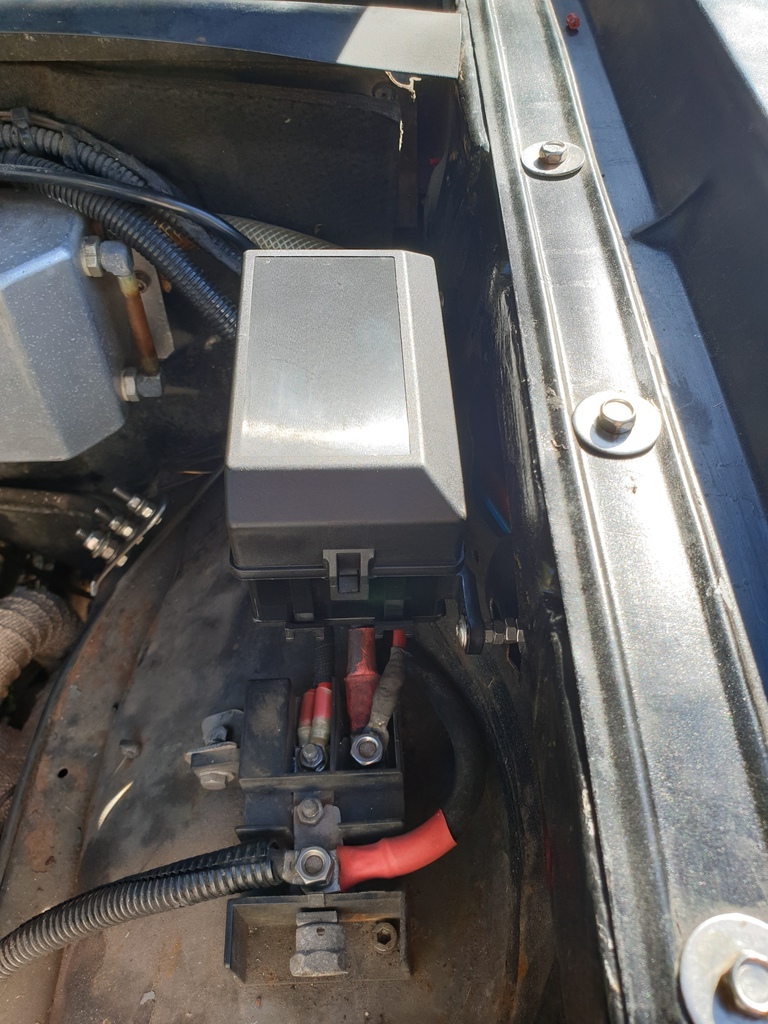 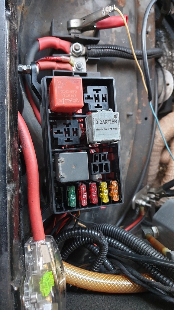 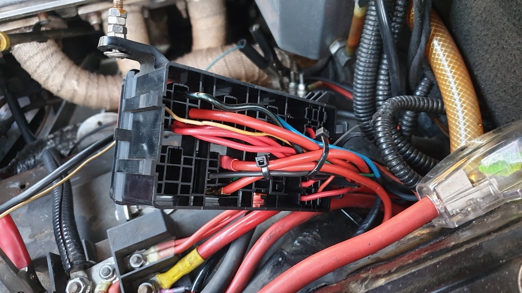 |
| |
|
|
eurogranada
Europe
To tinker or not to tinker, that is the question...
Posts: 2,555
|
|
|
|
I personally have little doubt that you will have this beautiful car returned to full running capacity but better than ever, I have nothing but total admiration for those who can meddle with "the black art", (ie - electrics,) Nigel Thanks for the vote of confidence! But, I'm by far a wonder in what you call "the black art" though. I get the basics mostly and simple circuits I can create, but there's plenty I'm not too sure of. In this case I'm reverse engineering what someone else once made for me and improving a little on the quality and fitment. I don't think there really is anything wrong with how it was made but I feel that some connections could probably benefit from a different approach. Although I must say that I can now much better understand what does what in the loom. |
| |
|
|


 )
)


