jonomisfit
Club Retro Rides Member
Posts: 1,790
Club RR Member Number: 49
|
|
Dec 13, 2015 17:05:35 GMT
|
Not had a good weekend. Went out the workshop for a bit, but not feeling great so didn't really get much done. I finally ordered up a load of bits I needed, so hopefully over Christmas should get some progress on it all. Main focus will be on making up the rack adapters so I can get the front suspension all set and mount the rack. Decided I should spent this afternoon working out what to do for the seat on CAD. Mark 1 attempted folded bomber / race seat. 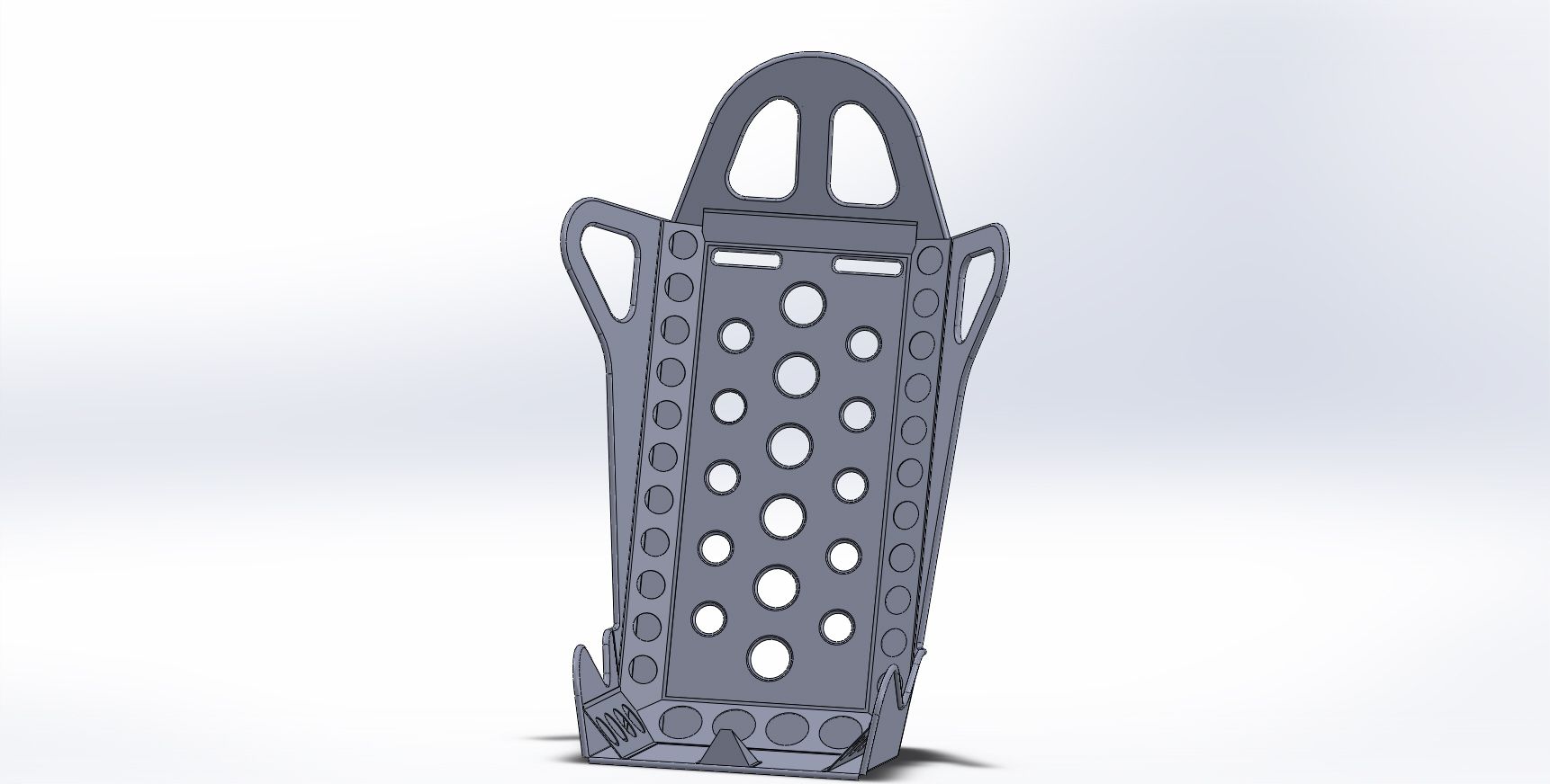 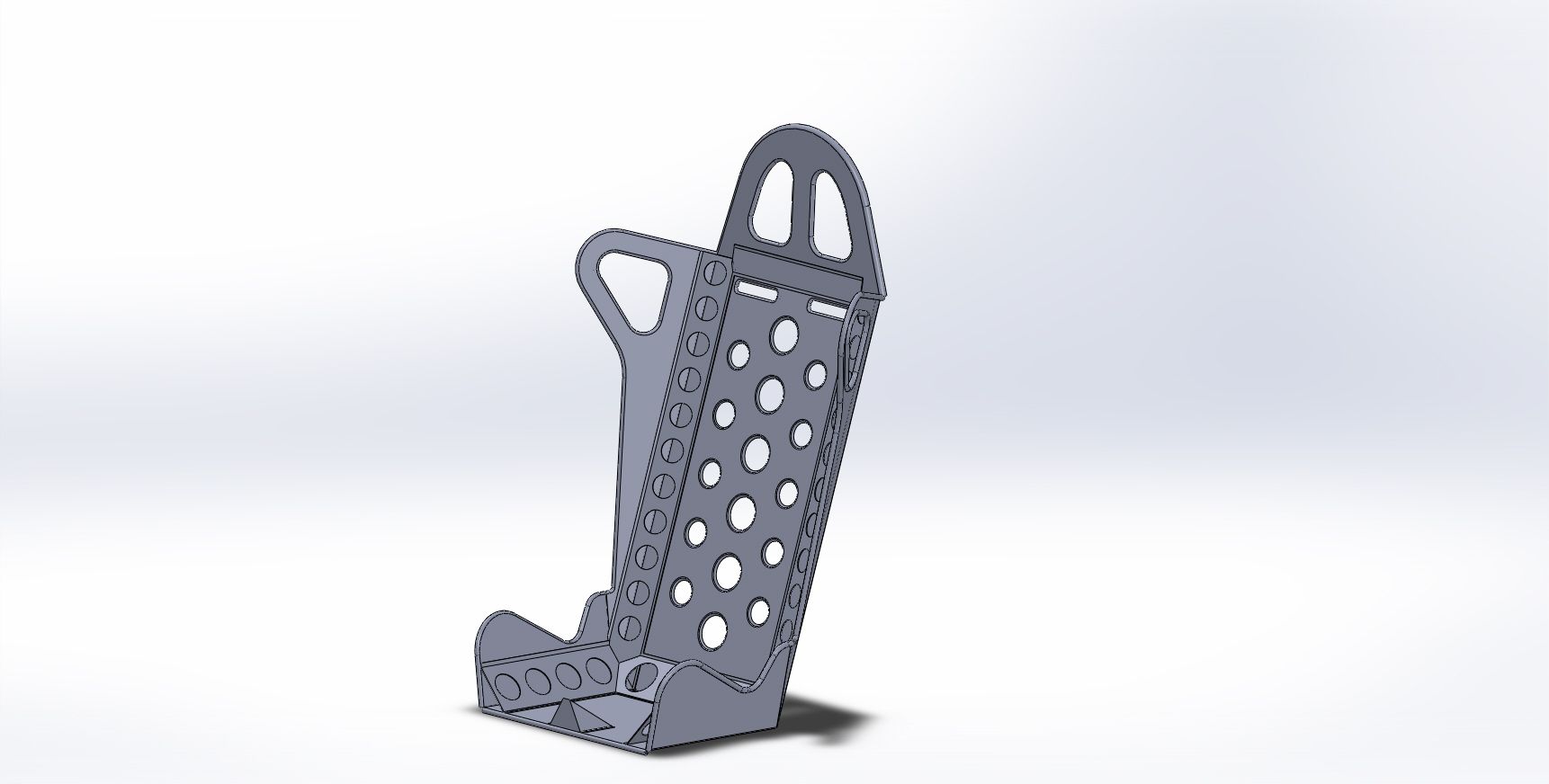 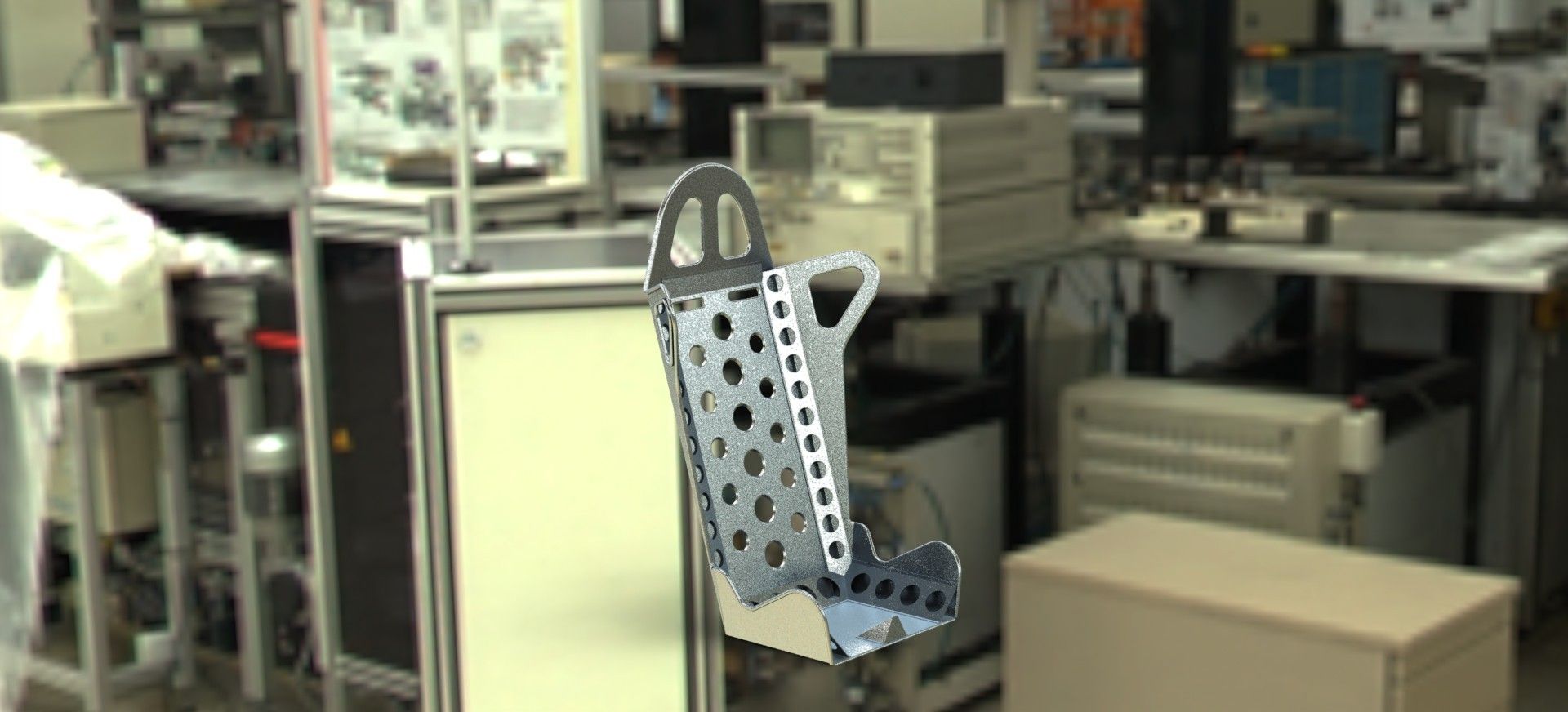 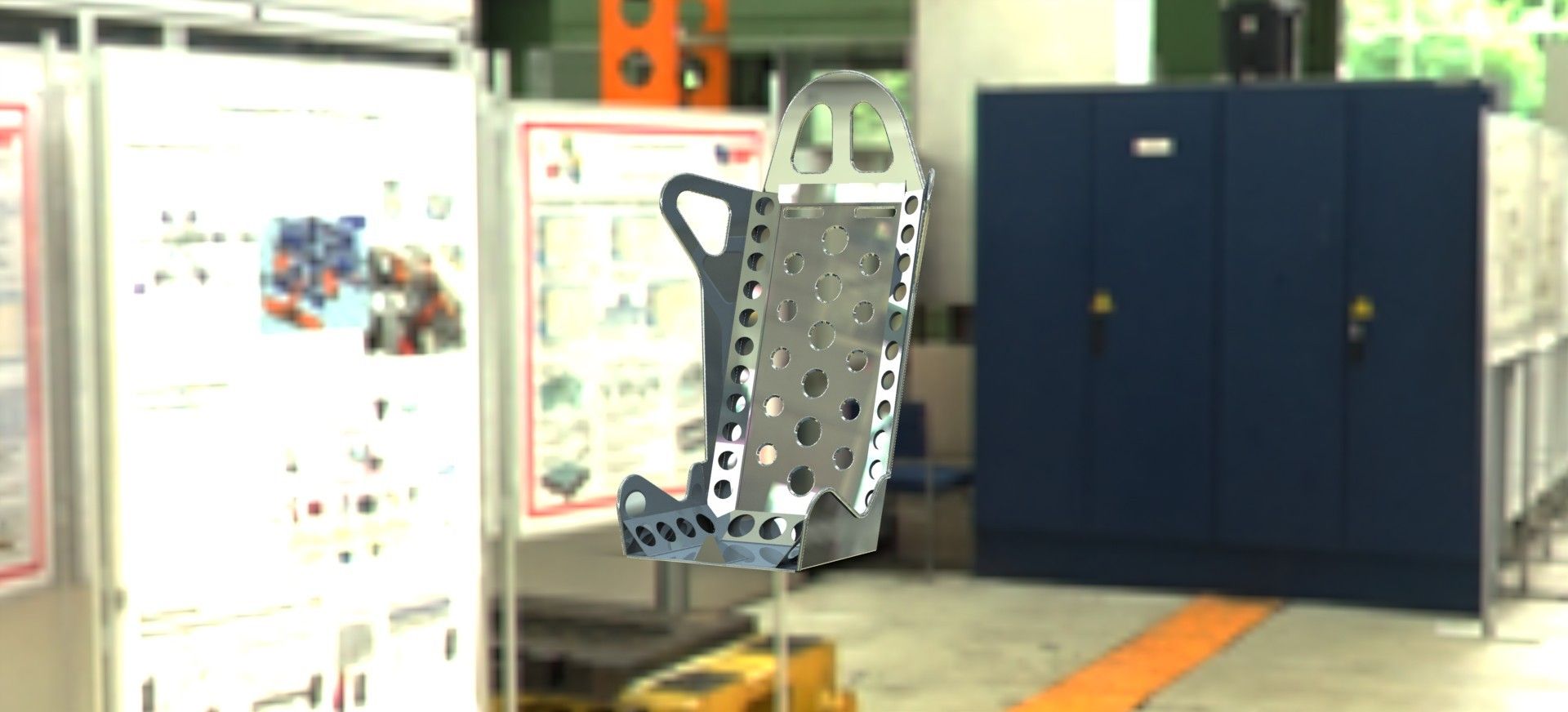 I'm not a fan of the top as it looks overly big, and i think the flat back doesn't look the best. I'm now on with designing a mk2 version with more of a segmented curved back. |
| |
|
|
|
|
vulgalour
Club Retro Rides Member
Posts: 7,286
Club RR Member Number: 146
|
|
Dec 13, 2015 17:45:01 GMT
|
|
Could you take an existing bucket type seat and deconstruct it to learn the shapes easier? If you got some cardboard and copied the basic shapes of an existing seat that should give you the proportions you want for the frame and suitable points to attach some padding for a modicum of comfort. I'd probably start with an existing seat frame and clad it to get the right look, a lot of your alignment and ergonomics are going to be done for you that way, surely?
|
| |
|
|
jonomisfit
Club Retro Rides Member
Posts: 1,790
Club RR Member Number: 49
|
|
Dec 13, 2015 21:42:56 GMT
|
|
That's sort of what I've started doing.
I found some plans and some images with measurements on the web, and my designs are based on those.
I've also taken measurements from the seats I have at home.
I'm going to refine the design till i get something I'm happy with.
Next step will be to make in ply to see if the basics works.
Padding will be glued on neoprene type placed at strategic points.
|
| |
|
|
|
|
|
|
|
I think instead of CAD, cellulose-based CAD will help a lot  Sturdy corrugated stuff. *n |
| |
Top grammar tips!
Bought = purchased. Brought = relocated
Lose = misplace/opposite of win. Loose = your mum
|
|
|
|
|
Dec 14, 2015 20:57:05 GMT
|
|
Or Meccano.
|
| |
 Click picture for more |
|
jonomisfit
Club Retro Rides Member
Posts: 1,790
Club RR Member Number: 49
|
|
Dec 20, 2015 21:12:29 GMT
|
Today was a lathe day. I needed 4 more bobbins for the passenger side rear arch support so spent a few hours making them. I'm not very quick on the lathe. Old trust 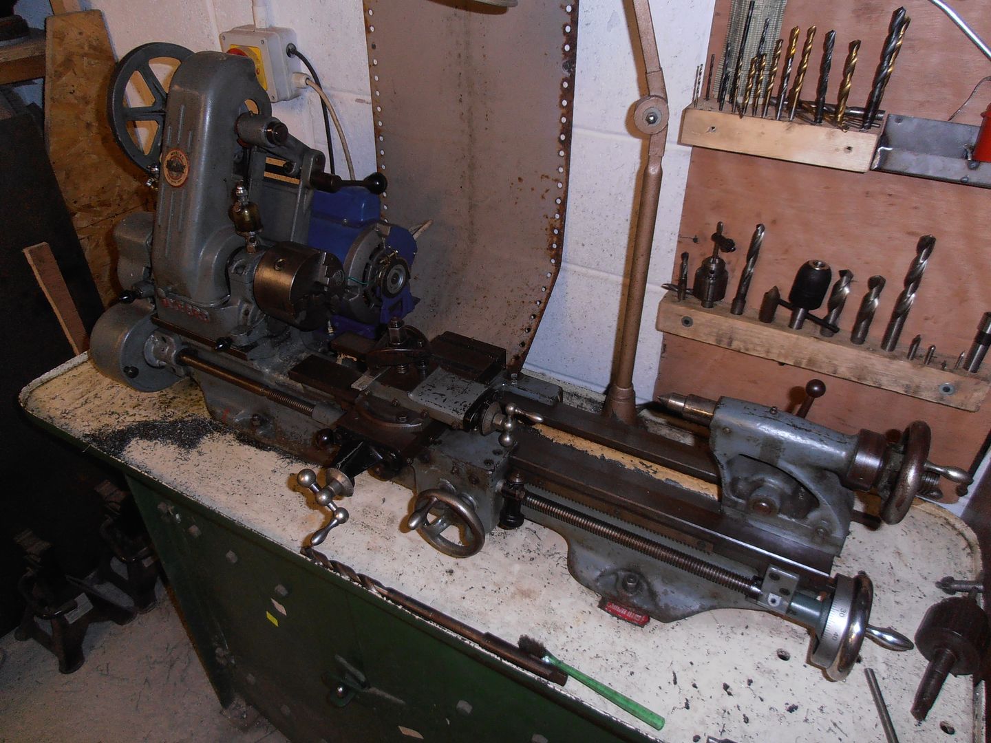 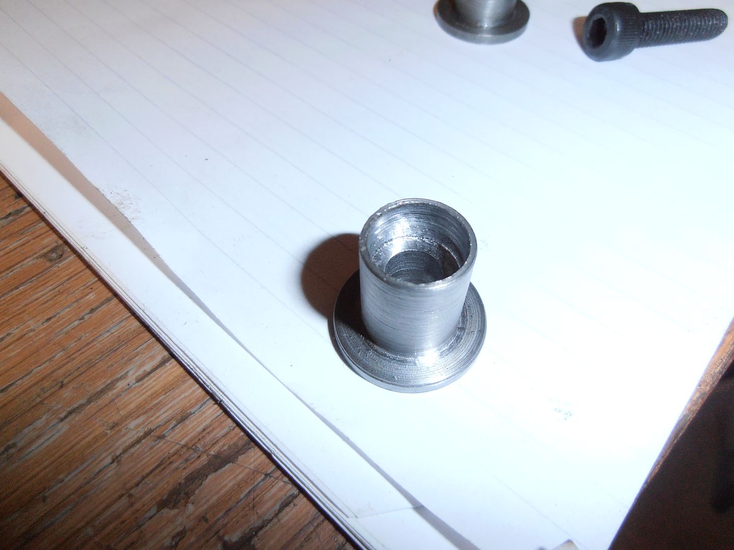 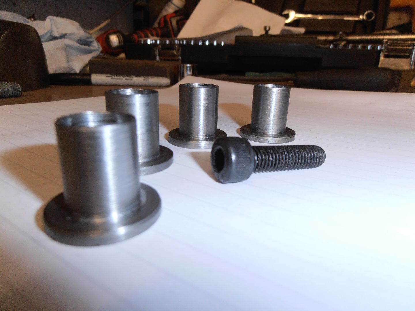 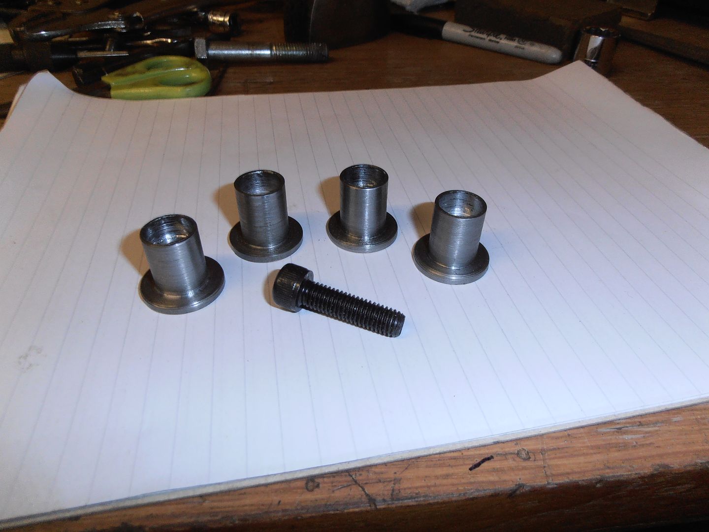 Also spent some time tonight starting work on seat mk 2 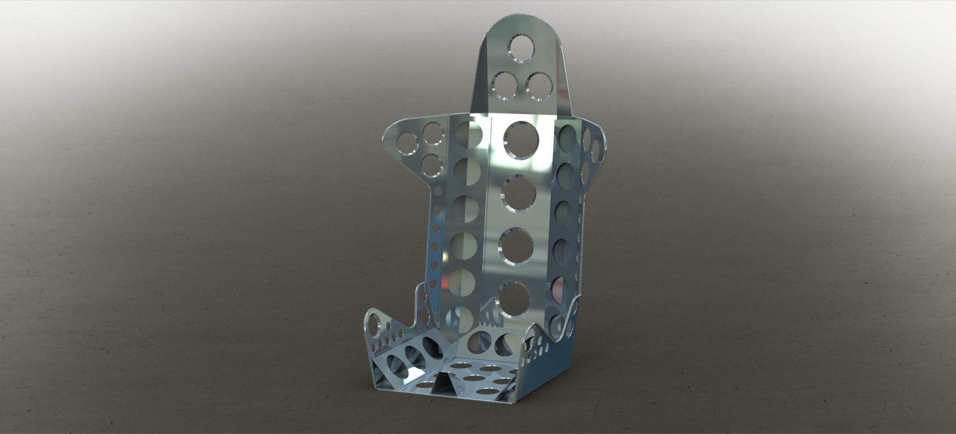  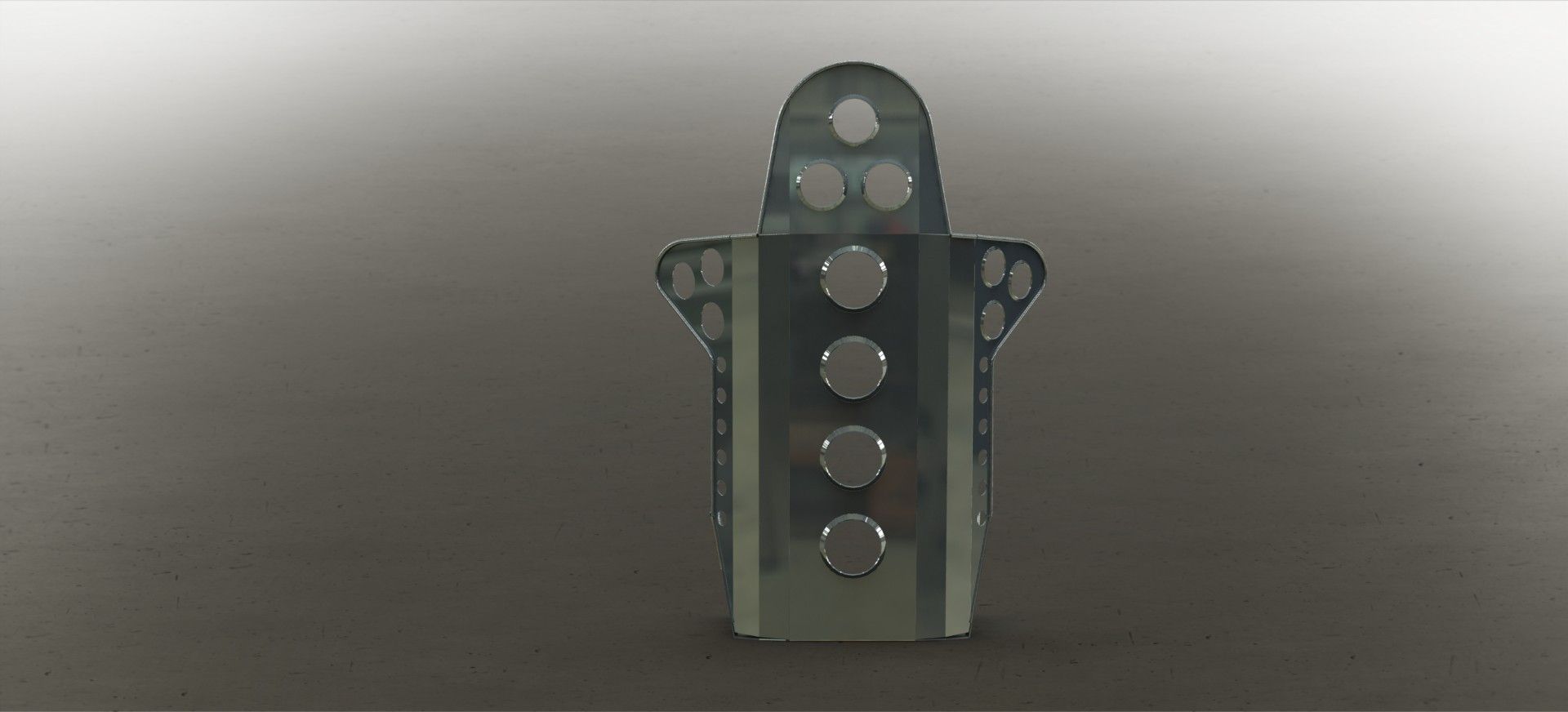 Bit better shape. I'm also working out what holes i think look good. Its current state is a bit over holed... swiss cheese seat at the moment :-) Hopefully get more done on the car this week. |
| |
|
|
jonomisfit
Club Retro Rides Member
Posts: 1,790
Club RR Member Number: 49
|
|
Dec 22, 2015 21:13:02 GMT
|
Decided to be productive on the first day of my holiday and turn some more parts. I need to get the rack mounting and steering sorted out and it been waiting for me to machine up an adapter from the upright to a rod end. This is so I can move the steering joint above the steering arm rather than below it. As this is just a mock up one to allow setting of the steering rack, its made out of mild steel. The proper one will be made out of EN24 but I want to know what it needs to look like first. Much turning on the lathe later... 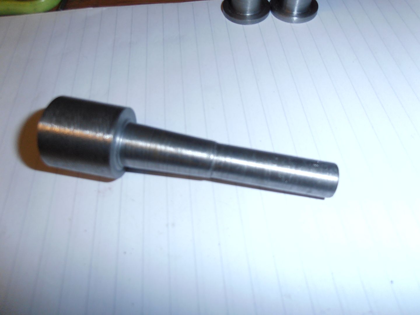 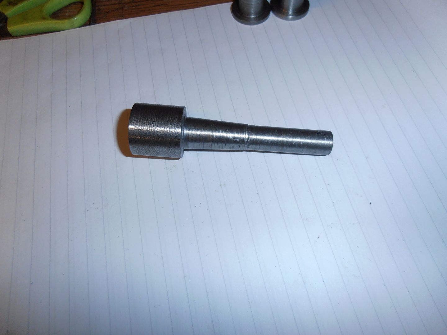 I had to cut a taper section to go into the taper on the steering arm. I took a load of measurement and then worked out the angle. The proper way of cutting the taper is to set the tail stock over. I've not got any drive dogs to allow between center turning so had to set and angle on the top slide and use that. It worked quite well. The bulbous bit at the bottom isn't needed, but i was lazy so didnt cut it off. I then turned up a couple of tapered spacers for the rod end to the shaft. 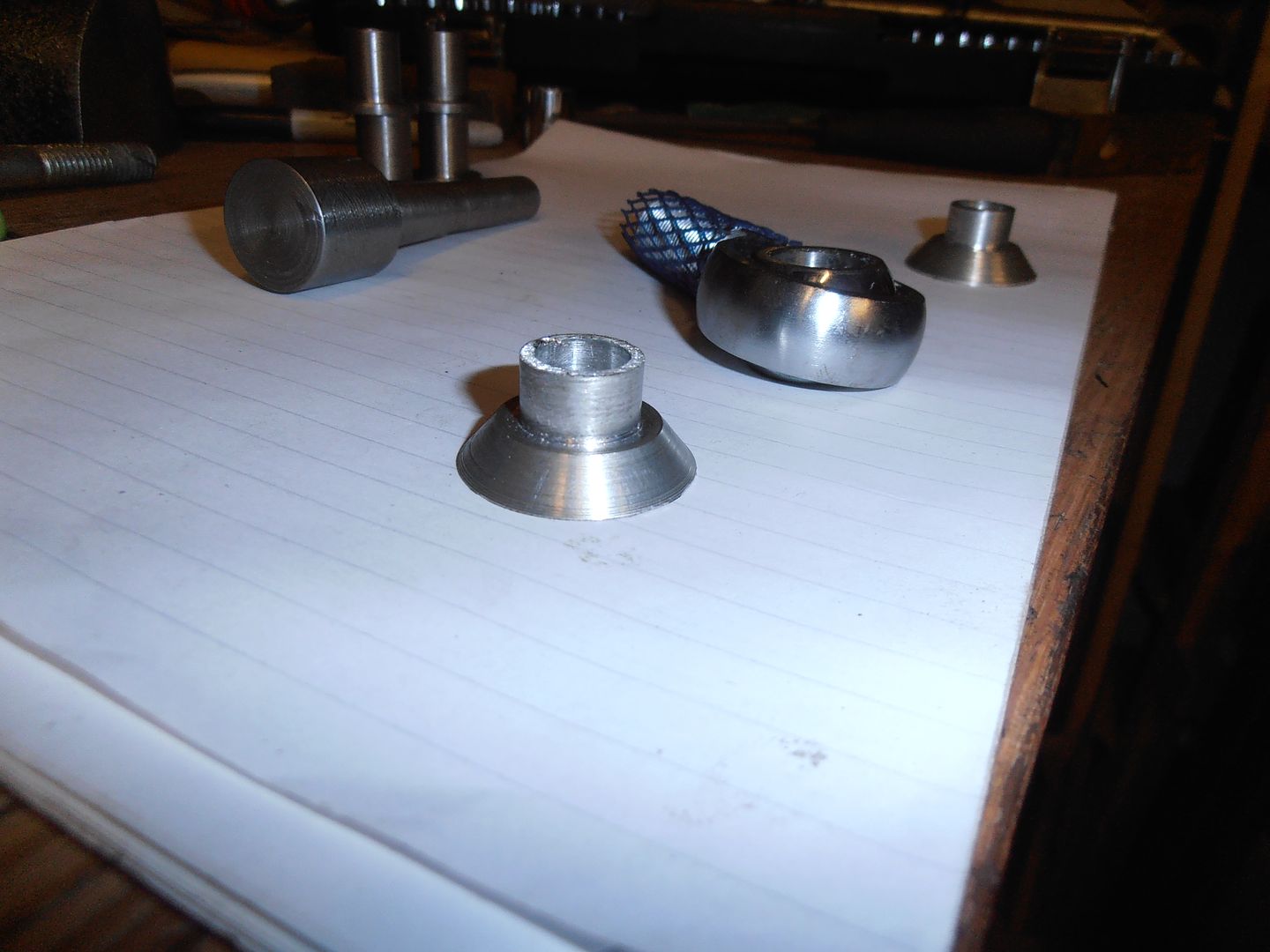 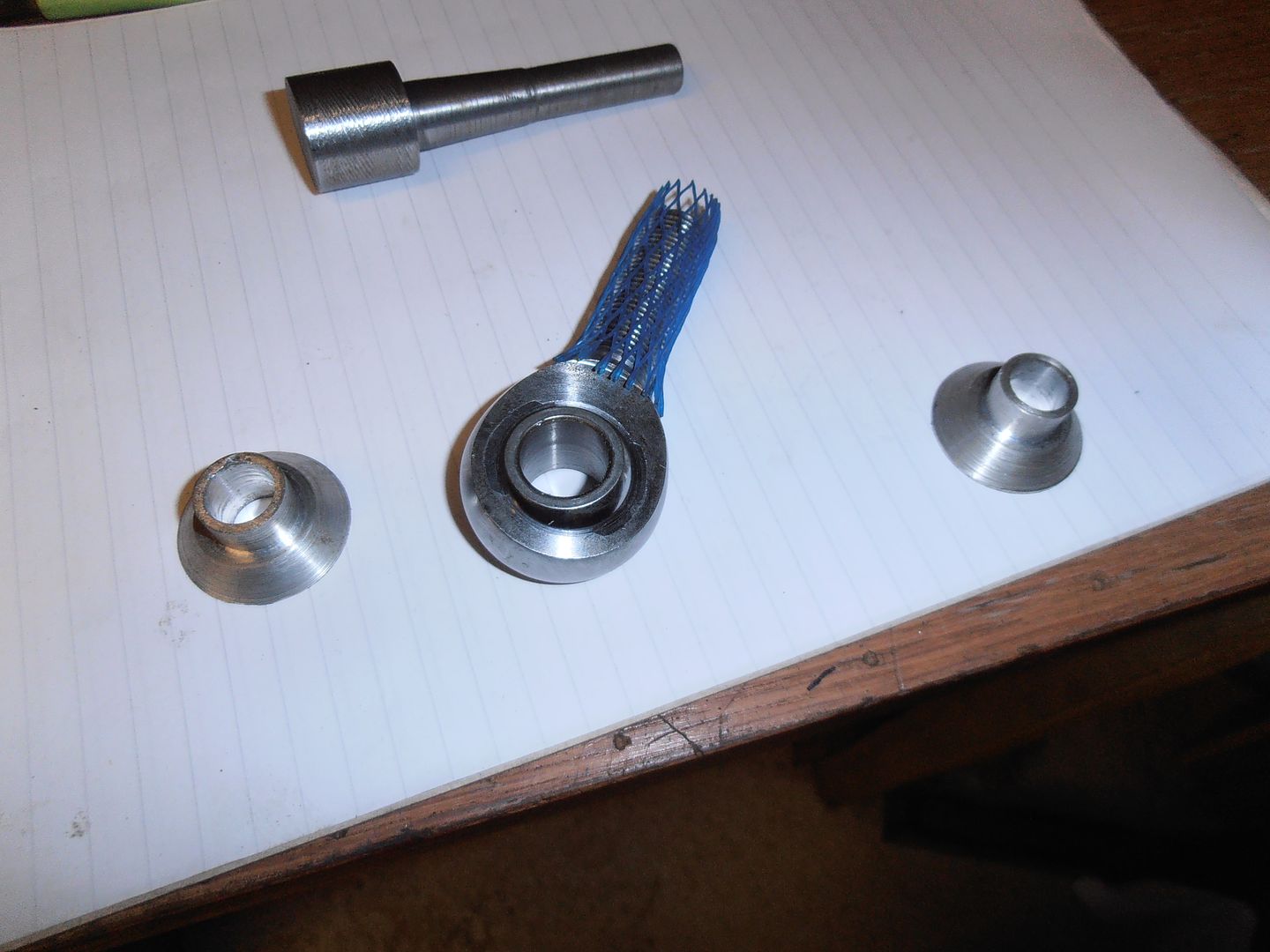 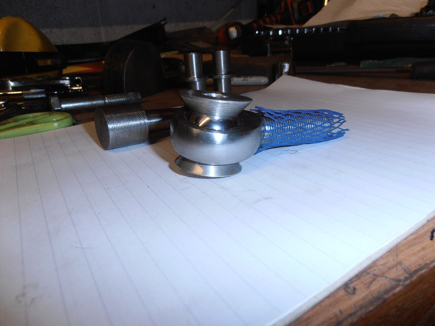 Parts assembled then look like this.  and on the upright. 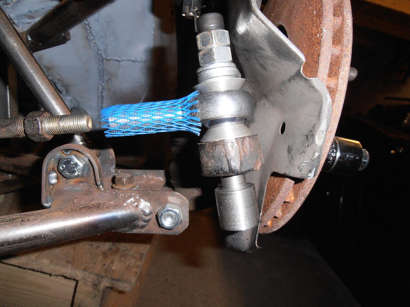 Considering it isn't cut the right way, the taper fitted fairly well and when lightly tapped in it grabs well. The shaft is over long to allow for some vertical adjustment of the rod end position. Once its all sorted out it'll be changed to the correct length. The washers and nuts are just temporary to hold it together. Next step will be trying to get the rack into the right position to minimise bump steer. |
| |
Last Edit: Dec 22, 2015 21:15:44 GMT by jonomisfit
|
|
mylittletony
Posted a lot
  
Posts: 2,426
Club RR Member Number: 84
Member is Online
|
|
|
|
Nice you that managed to get some productive work done in the break! You know that given your quick lashup worked so well the real taper won't work properly??  |
| |
|
|
|
|
|
Dec 23, 2015 10:51:52 GMT
|
|
Nice work,
|
| |
|
|
jonomisfit
Club Retro Rides Member
Posts: 1,790
Club RR Member Number: 49
|
|
Dec 23, 2015 20:56:29 GMT
|
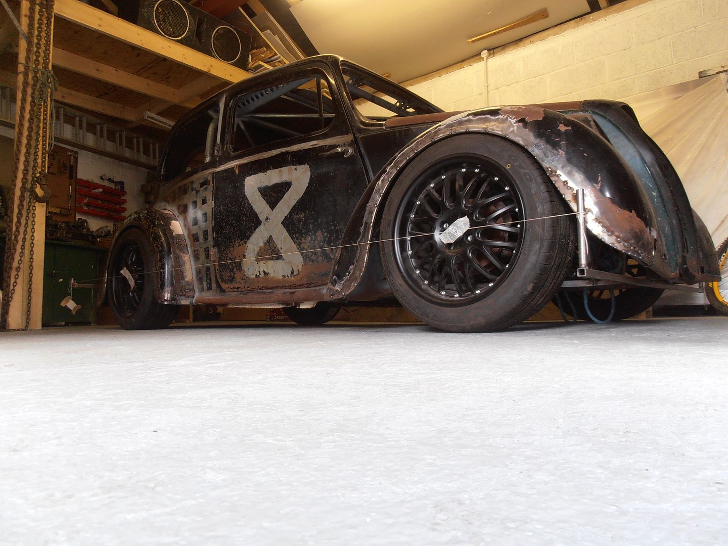
Got another few hours in the workshop today, so made the other adapter I need to start getting the rack position sorted. Turned up an adapter from M12 x 1.25 RH thread (for track arm) to 5/8UNF LF for the rod end.  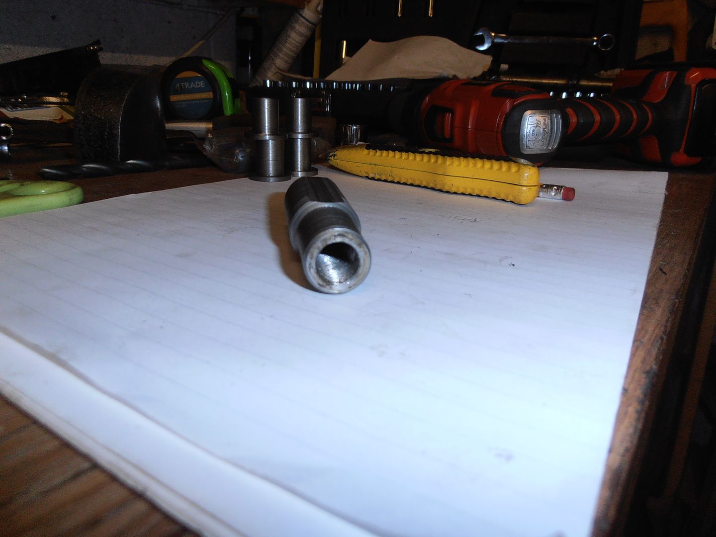 I also milled it to 20mm across flats so I can stick a spanner on it to adjust it. 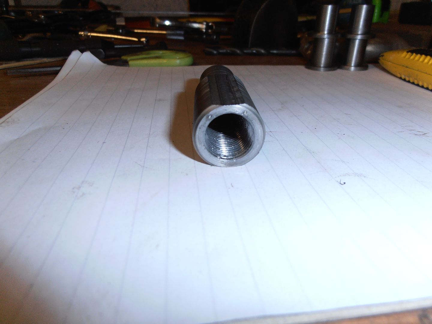 Assembled onto the other bits I made yesterday 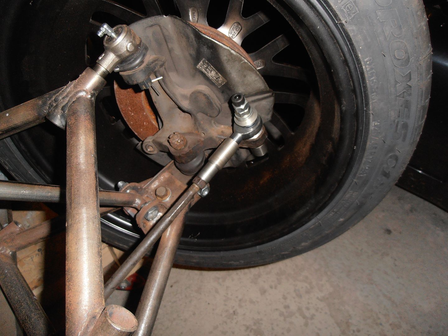 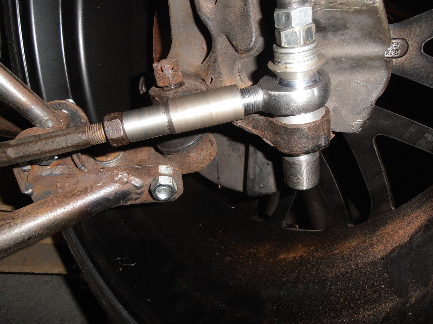 Just need to spend a while now setting up suspension and dialing out the bump steer. Full lock full bump clearance is good. 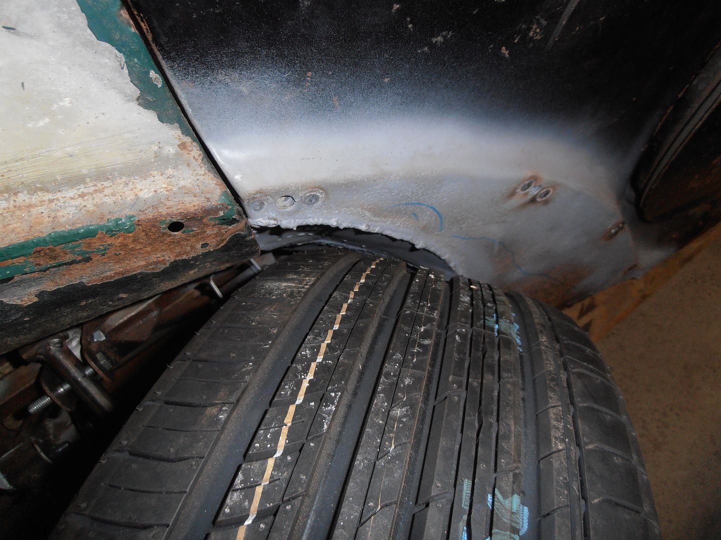 in both directions.  I also think the car look quite mean :-) 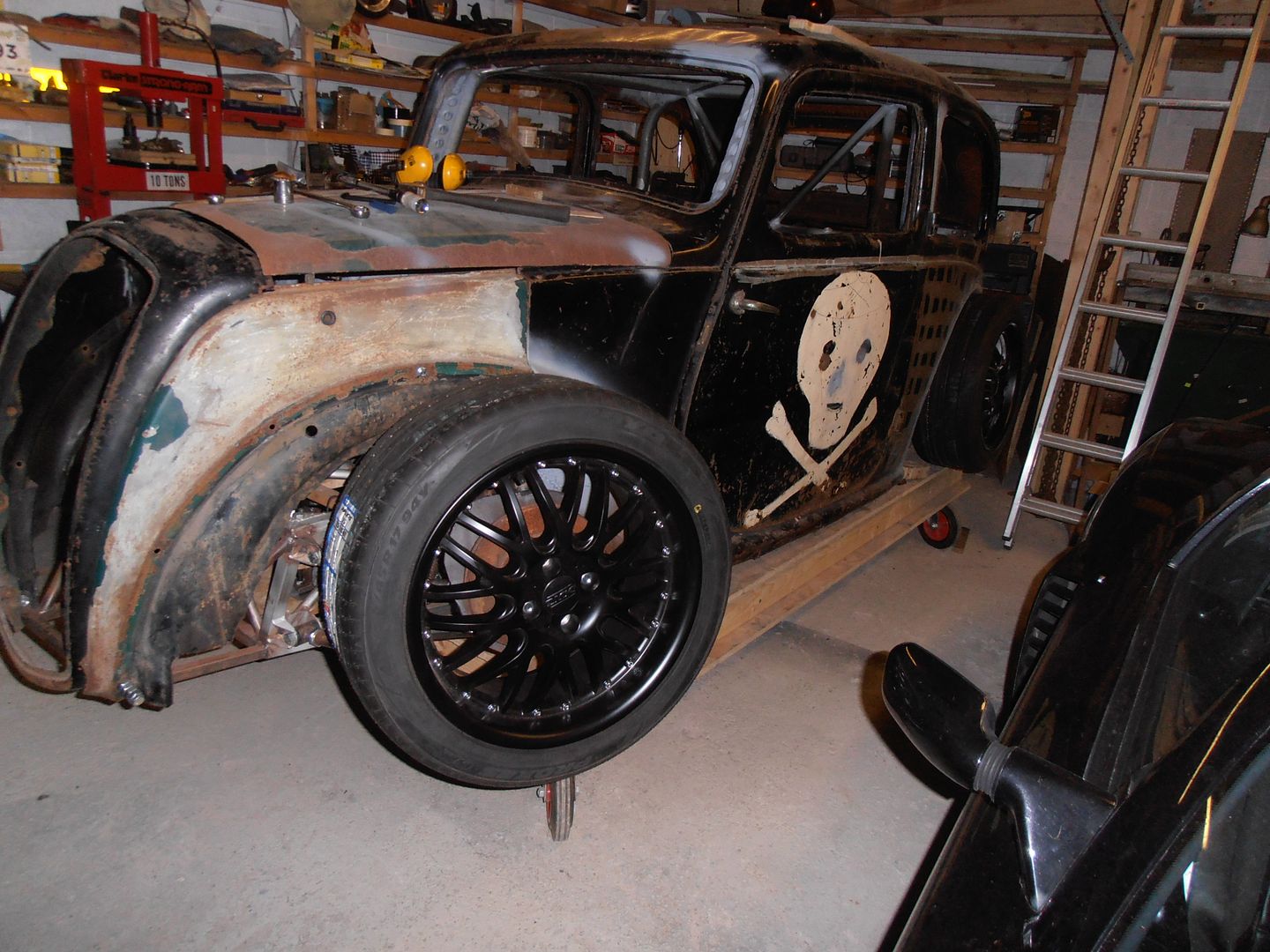 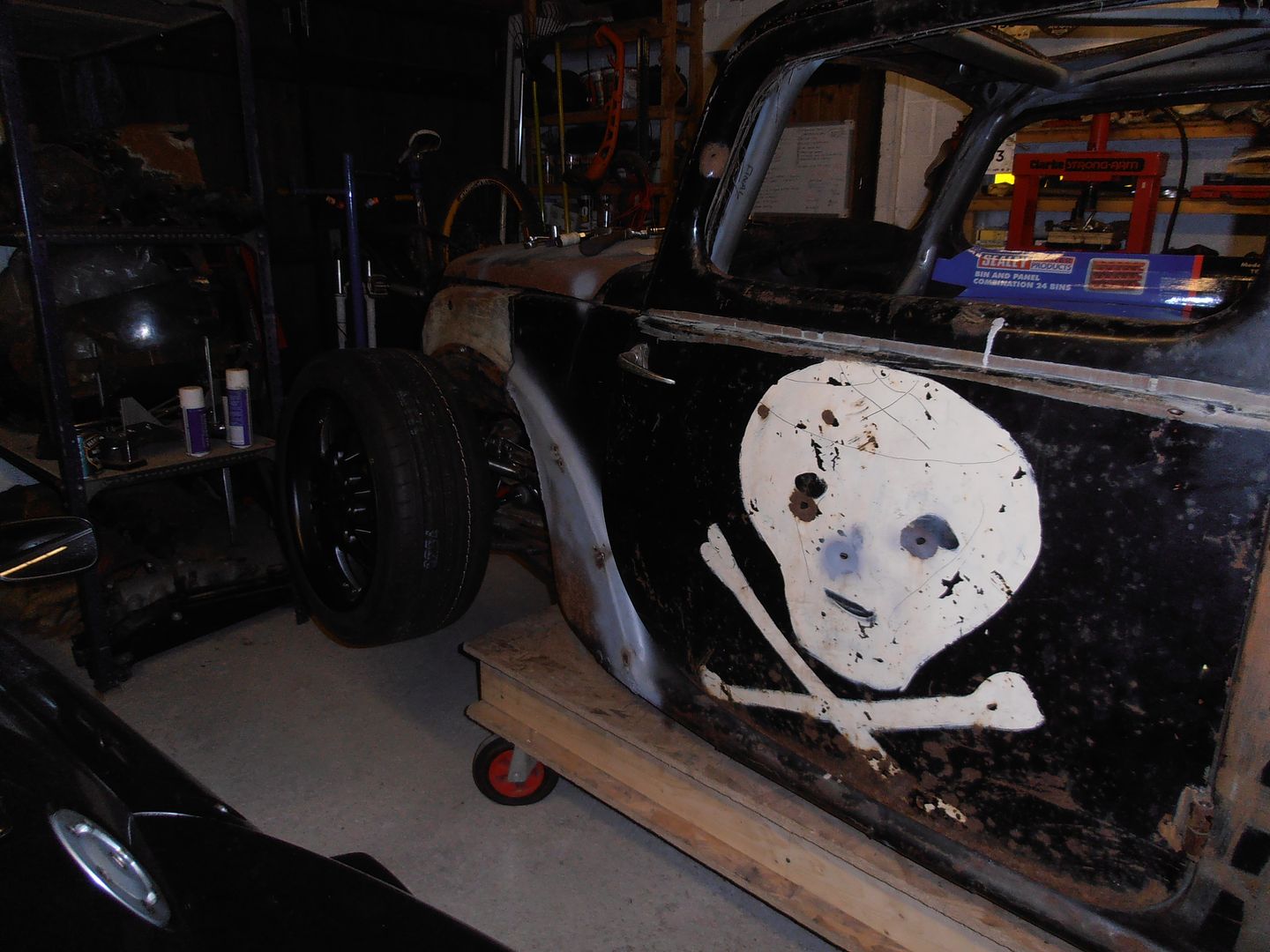 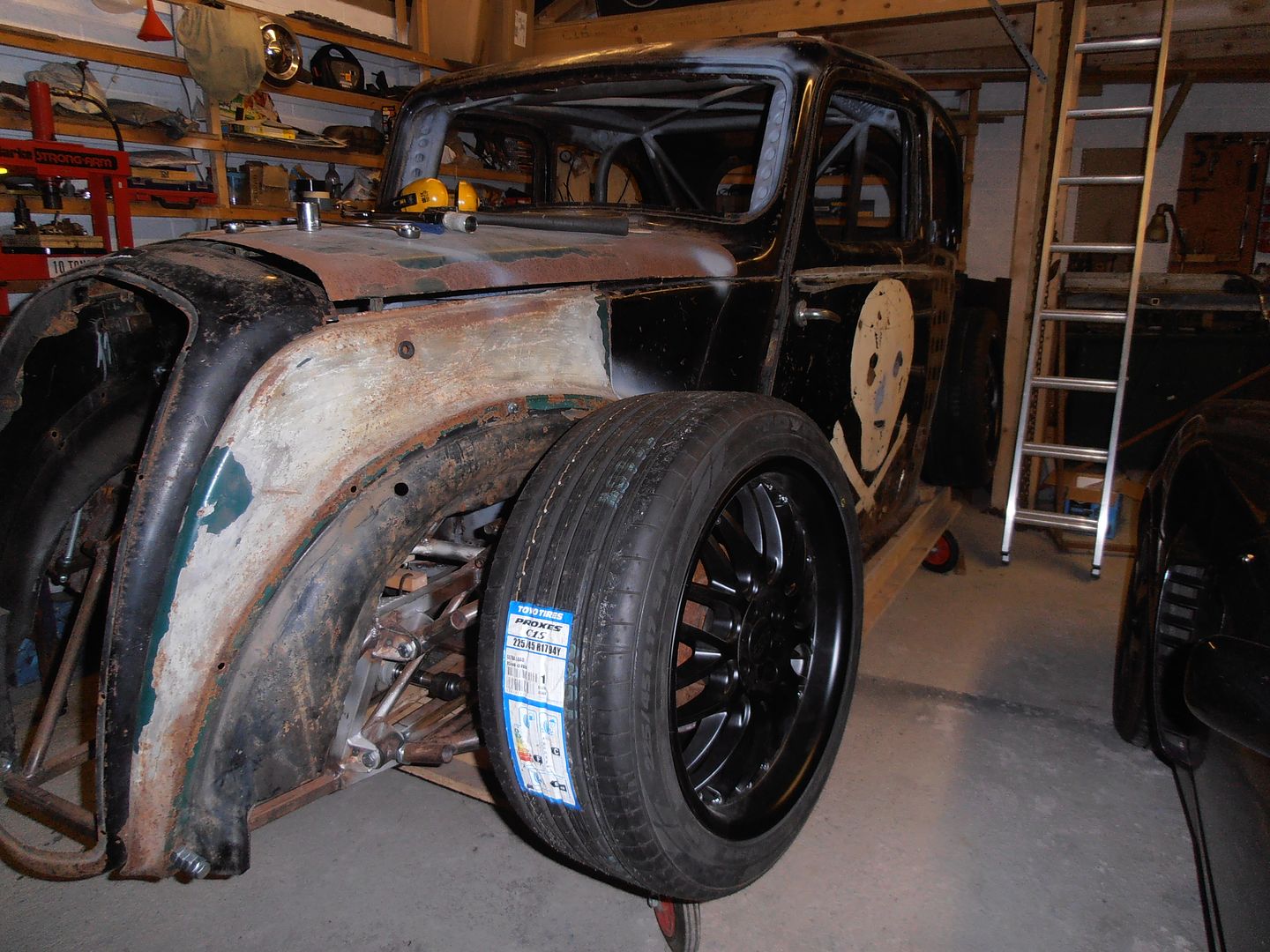 Not sure when I'll get onto the car next. Probably January. |
| |
|
|
|
|
|
|
|
|
|
|
Mean stance. Quite like the skull and cross bones haha
|
| |
|
|
mylittletony
Posted a lot
  
Posts: 2,426
Club RR Member Number: 84
Member is Online
|
|
|
|
...the car looks quite mean... UNDERSTATEMENT |
| |
|
|
heathrobinson
Part of things
  Broken everything
Posts: 848  Club RR Member Number: 111
|
|
Dec 25, 2015 12:36:32 GMT
|
|
It's quite easy to get lost in the wealth of detail in this thread, but seeing the car from a bit of a distance brings home quite how awesome this thing's going to be! Probably my most anticipated project roll-out!
|
| |
|
|
jonomisfit
Club Retro Rides Member
Posts: 1,790
Club RR Member Number: 49
|
|
Dec 27, 2015 20:41:08 GMT
|
Cheers Dudes. Having made the adapters it was time to check what else was needed to set up the suspension. Front end off again, and fit a leveled bar to give some reference 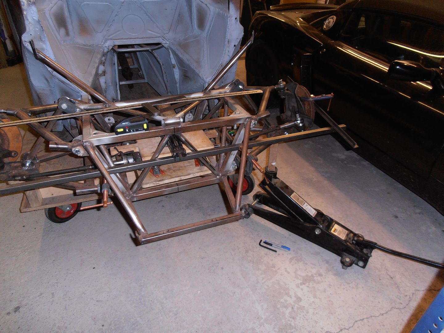 I then bolted some angle across the wheel for a quick indication of angle changes etc. 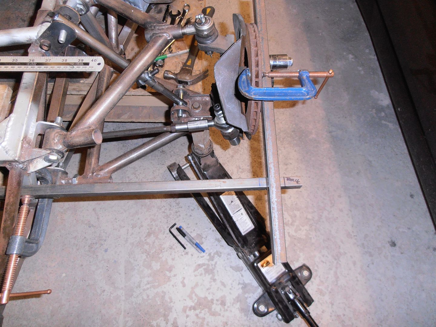 I needed to make a couple of adjustments to the tracking and camber. I pretty quickly got fed up of measuring upper and lower set points, so decided to make up a dummy damper that is of the correct maximum / minimum length 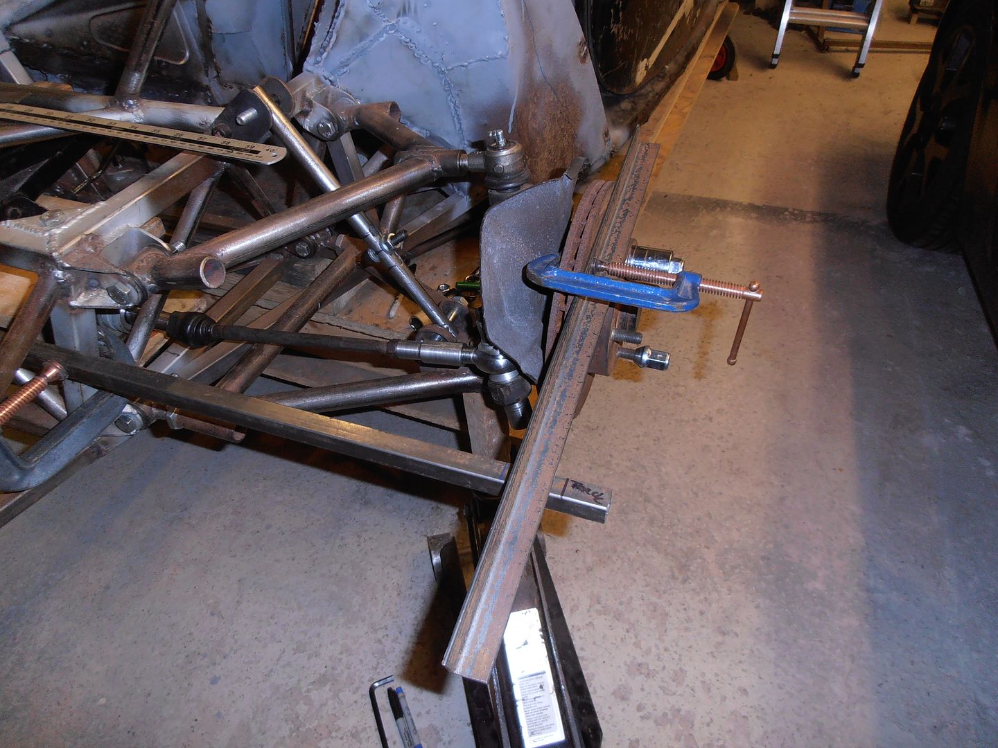 I used the mill to slot the right sized piece of tube 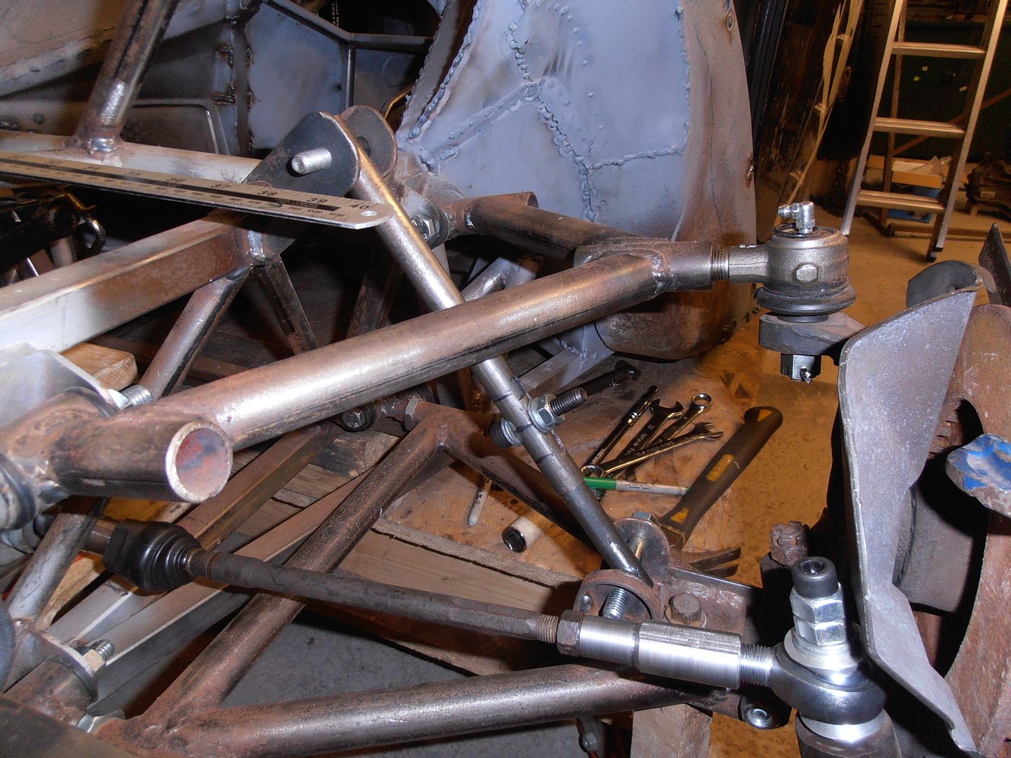 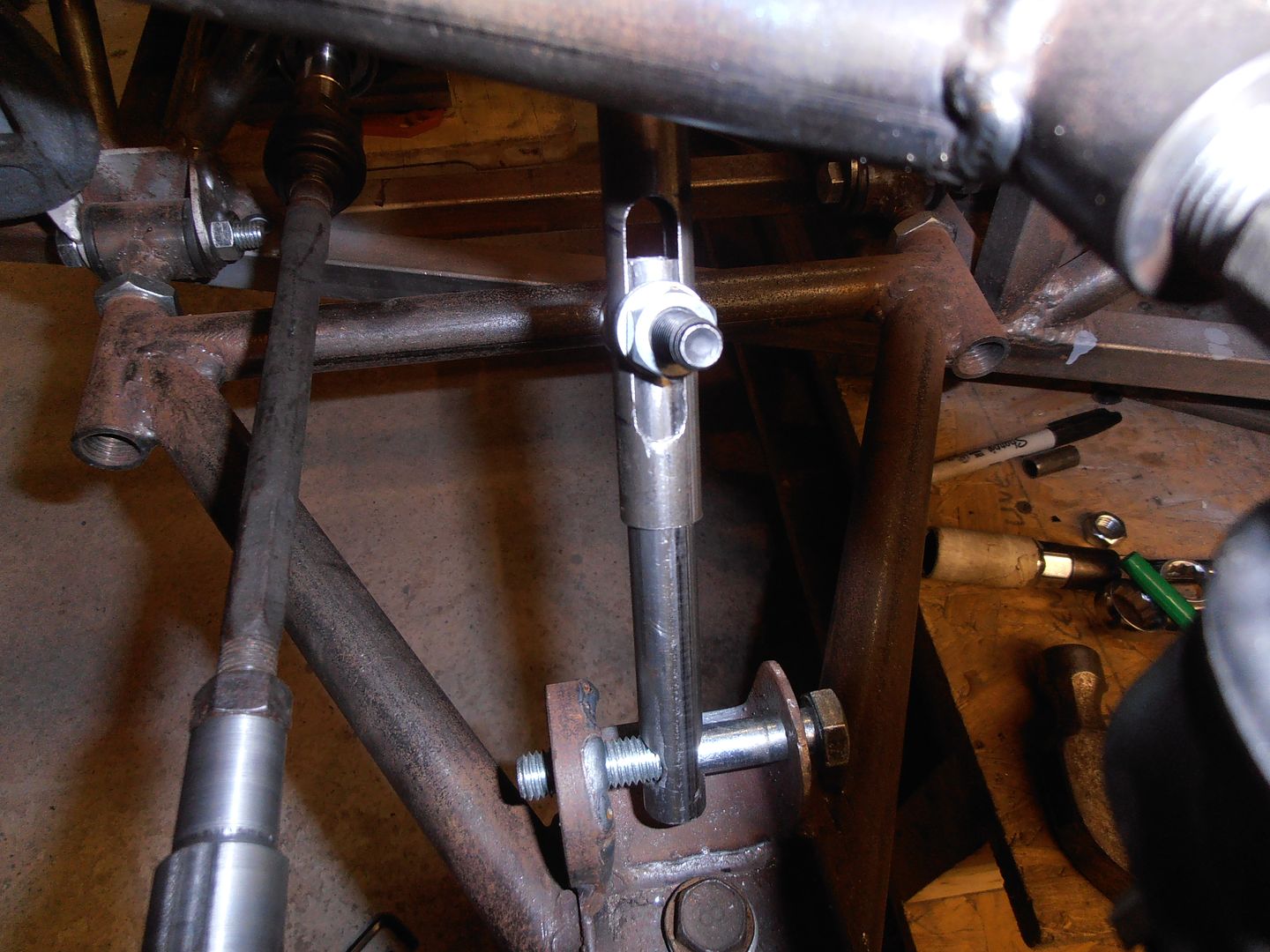 and marked it with the upper, lower, and mid positions... roughly... 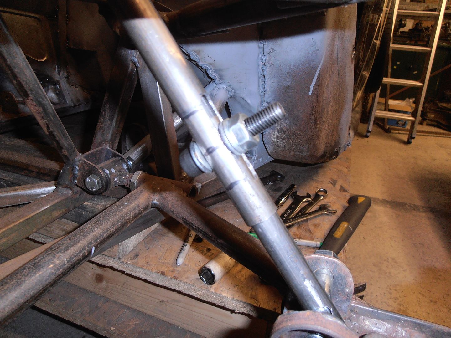 Excellent, now to make it go up and down... no... balls. Rod end catches on the top hats on full droop, need to make new ones with a slightly smaller seat to allow greater misalignment. Que two roughly made ones. 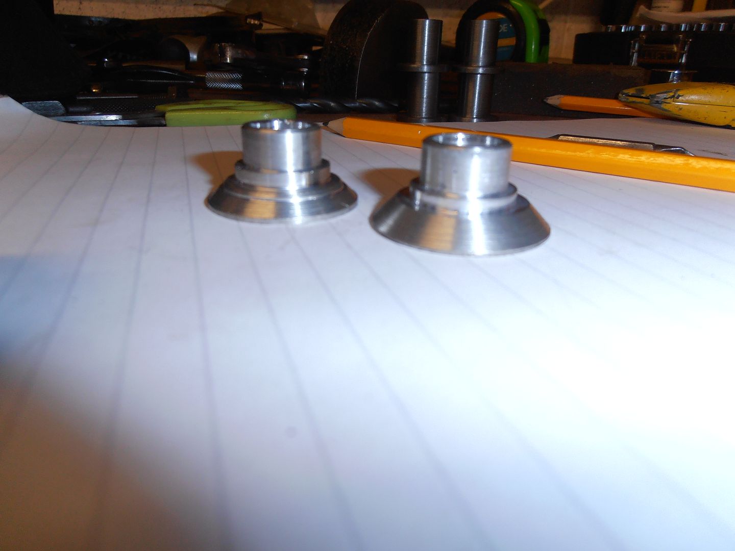 One has an extra step in it as I wasnt paying attention and the power traverse was on.... oops Give a lot more misalignment of the rod end, and a frankly over cut. But they can be used for setup and then re-made in final size once its all set up. 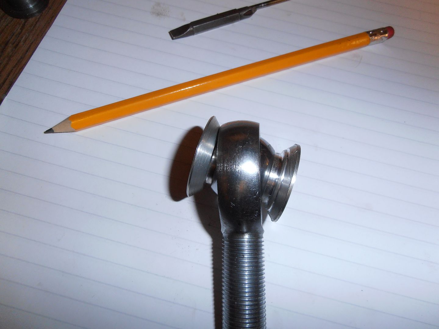  fitted 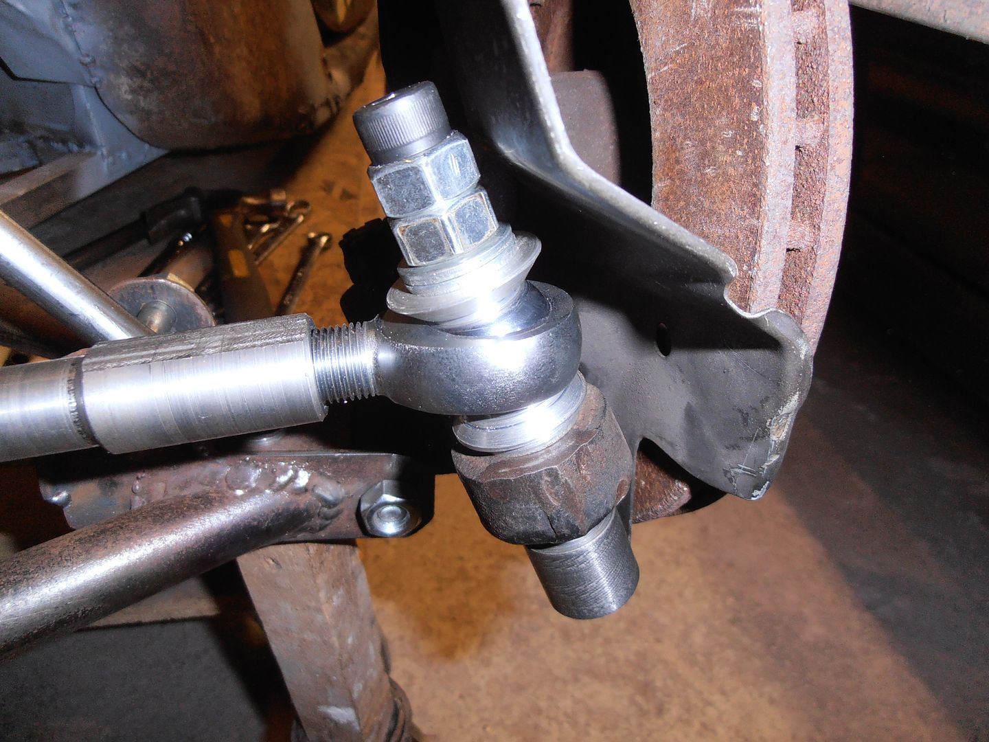 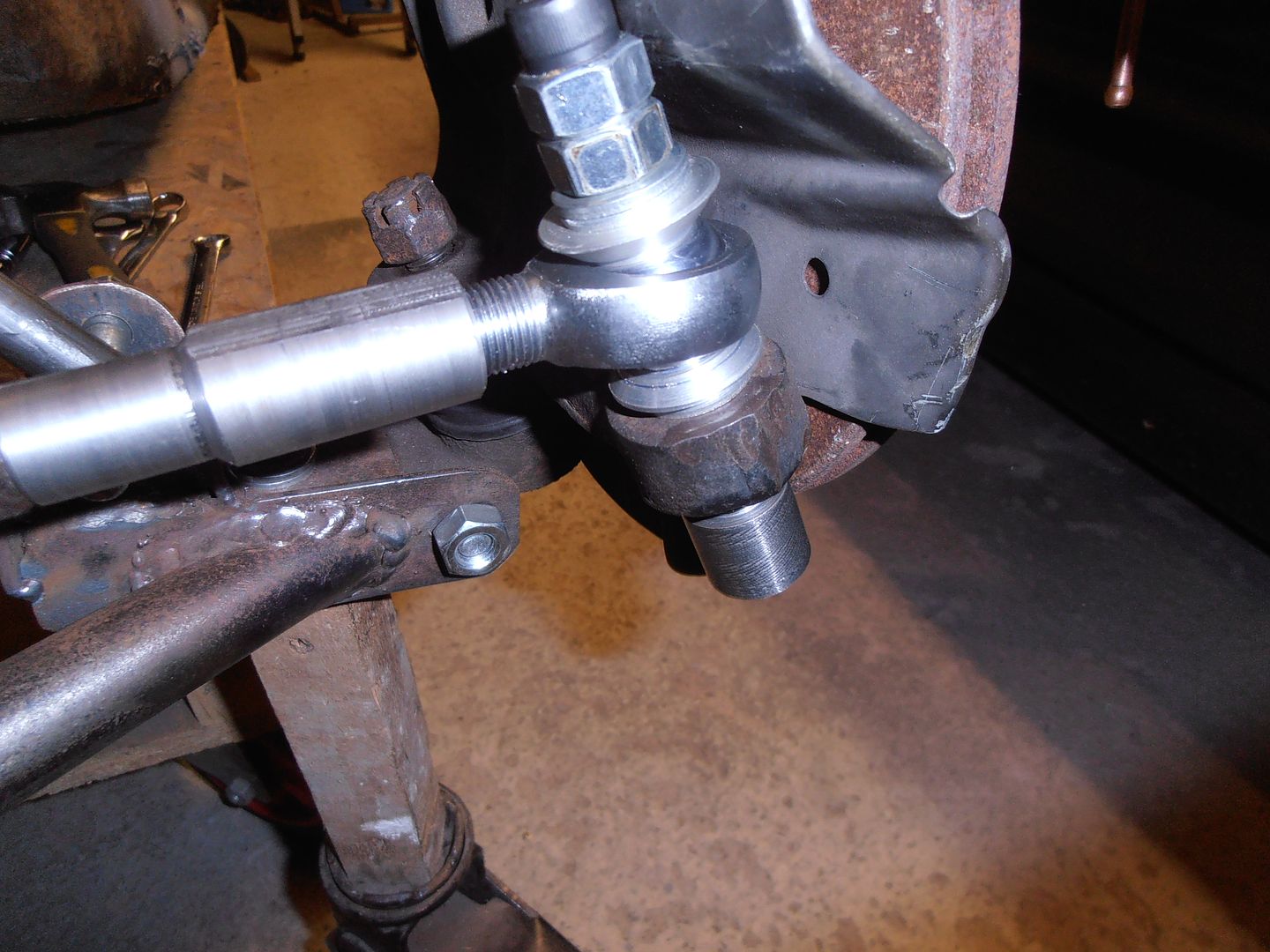 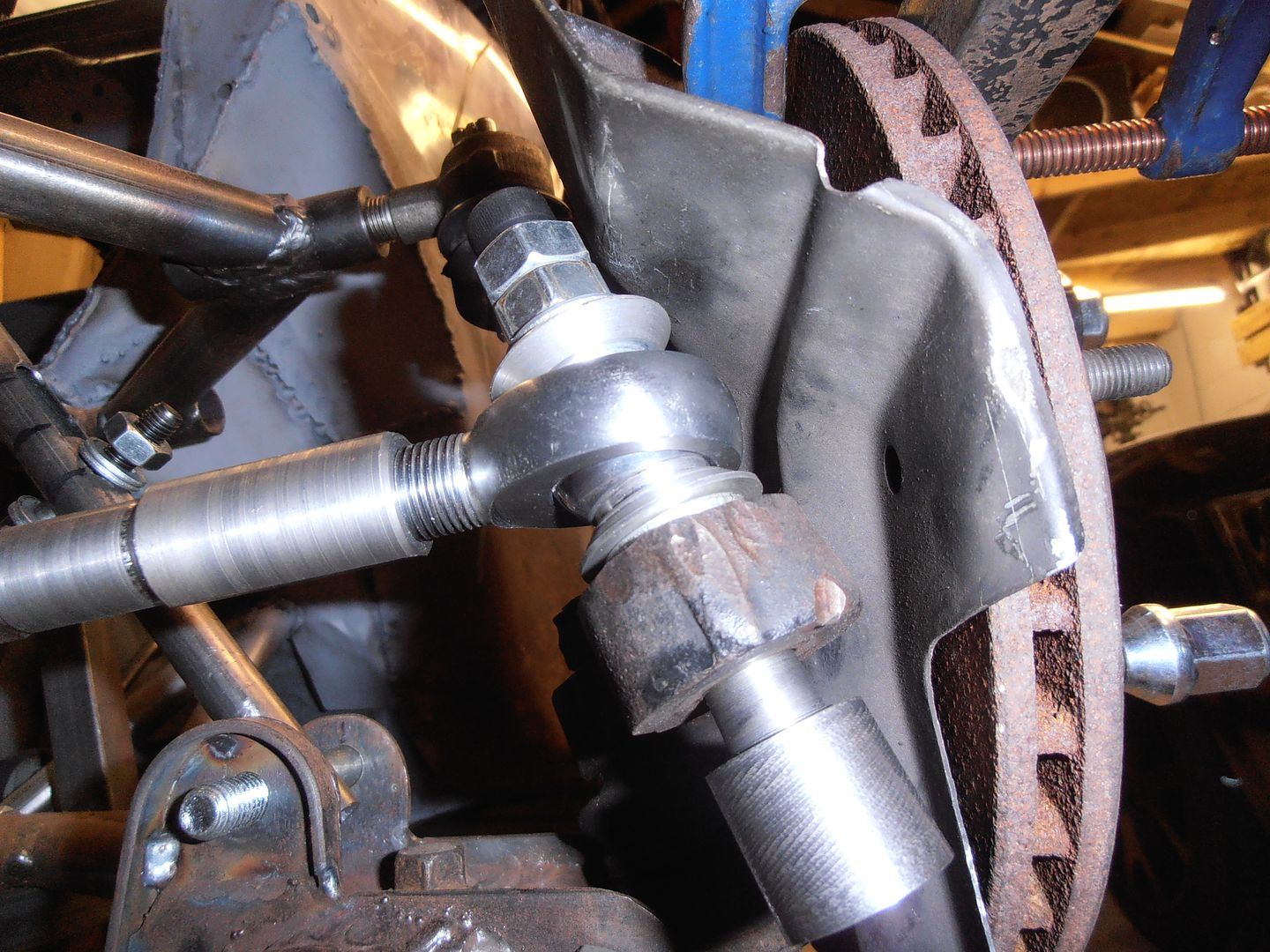 Will hopefully get closer to setting it all up tomorrow. |
| |
|
|
jonomisfit
Club Retro Rides Member
Posts: 1,790
Club RR Member Number: 49
|
|
|
|
Bump steer bump steer bump steer... I spent quite a while working on this. First things first. Accurate way of measuring required. There was an example of a setup in race and rally car source book, so made one of these.  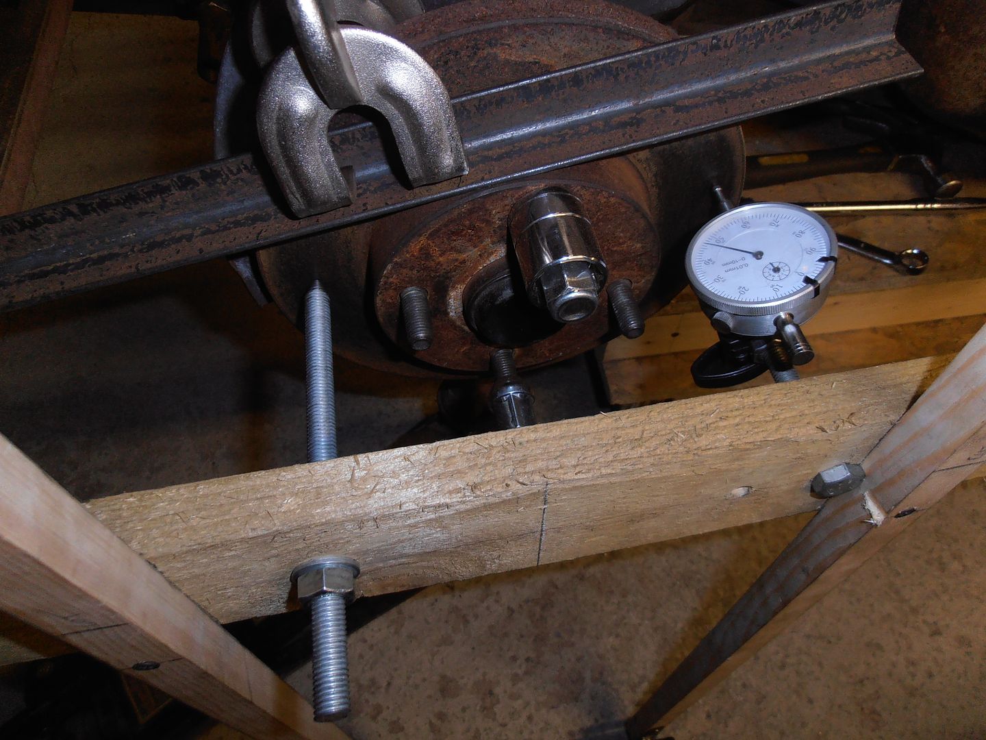 Left hand side is a length of threaded rod with a point turned on it. This sets a fixed distance for the bar from the surface. The other side is the clock. As the suspension cycles the hub turns for any wheel angle change and the reading comes up on the guage. 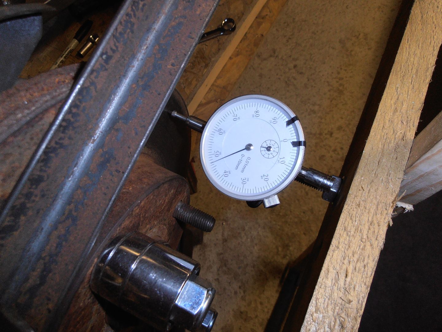 oh dear of dear. First go nets +/- circa 5mm change. rack is very much out. Pretty apparent the frame isnt sturdy enough either. mk2 frame (mk1 frame + extra plywood). very much stiffer 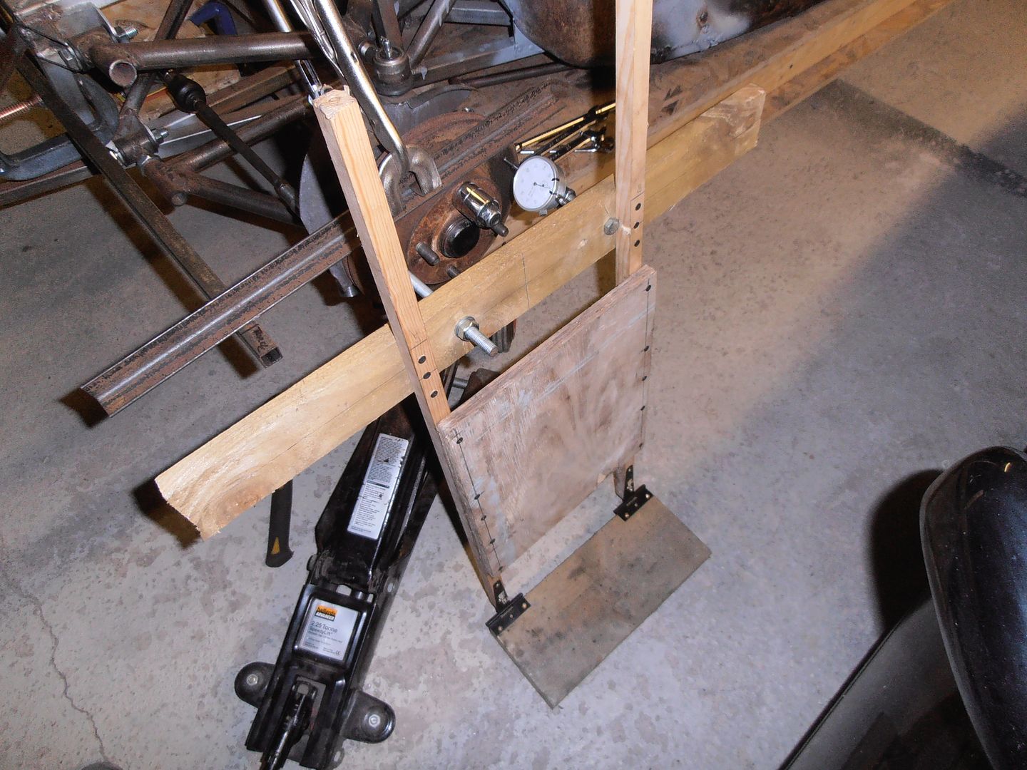 Next issue. moving the rack up / down accurately is a pain with the shims. Make a proper jig that maintains alignment. Rack base plate  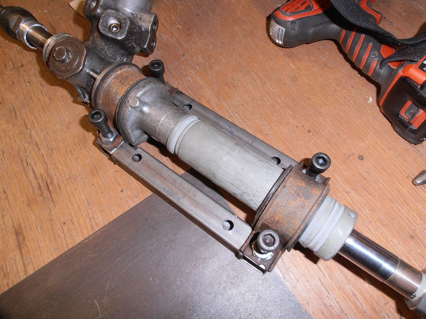 jig base plate 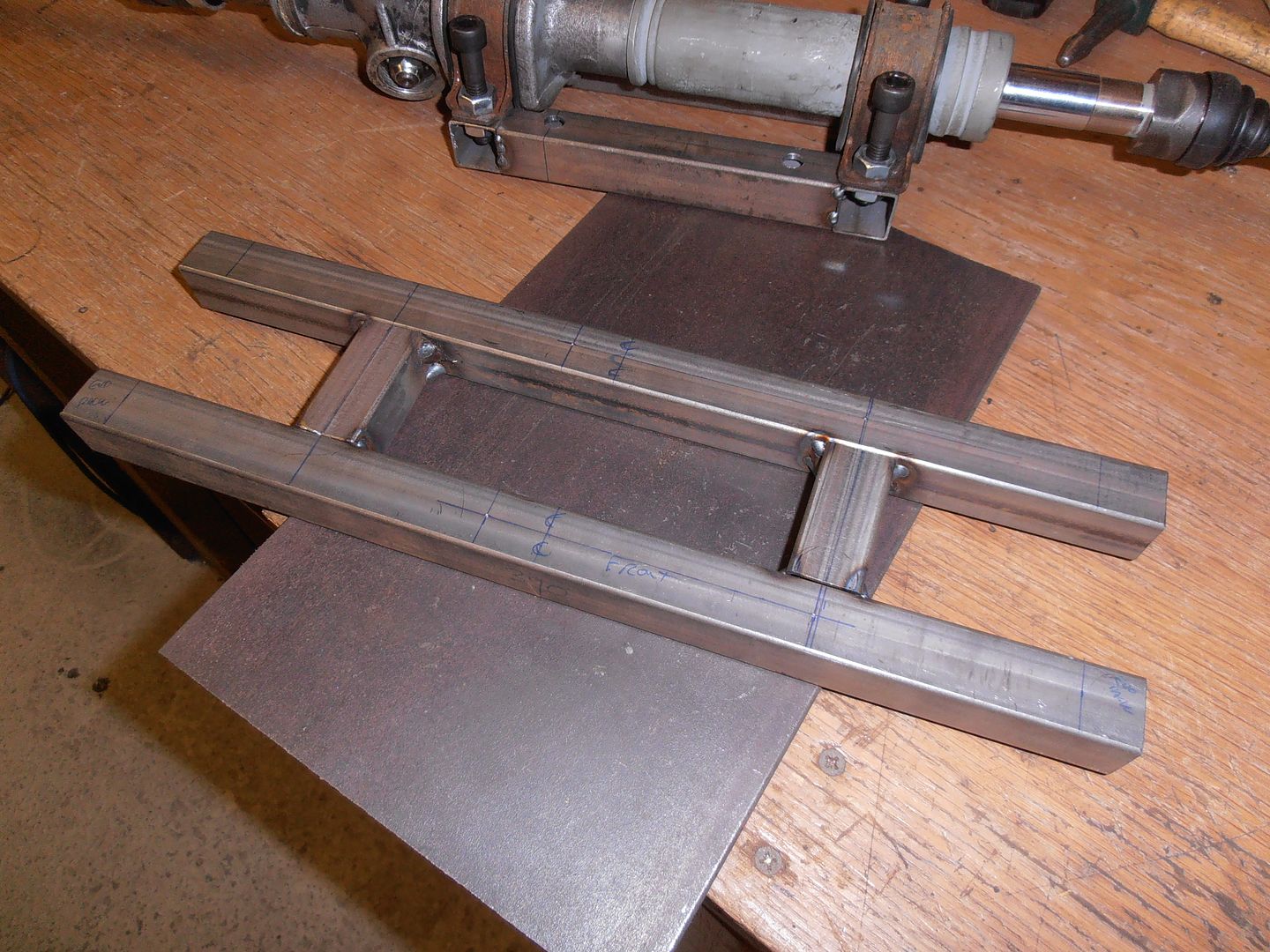 assembled. 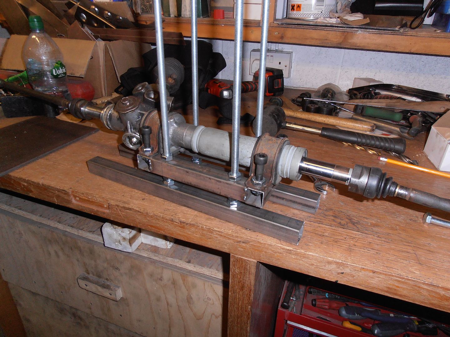 trial fit shows the rods are too long and get in the way. Cut them down and also weld into base to reduce amount of nuts required so rack can go lower. in situ 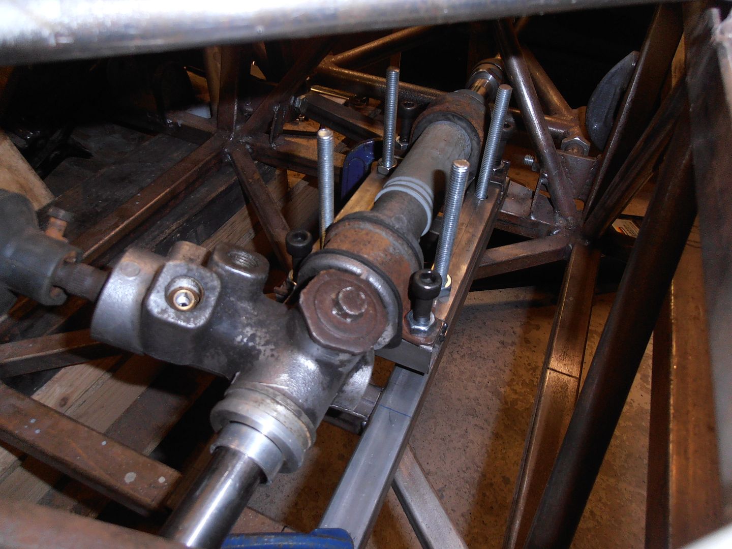 winding the nuts up / down raises / lowers the rack and means it can be locked in a fixed position. 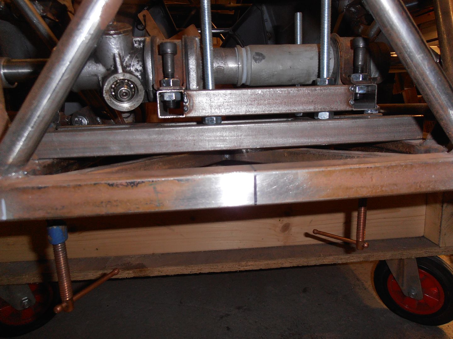 que a number of hours making it all go up and down, adjust rack, repeat. 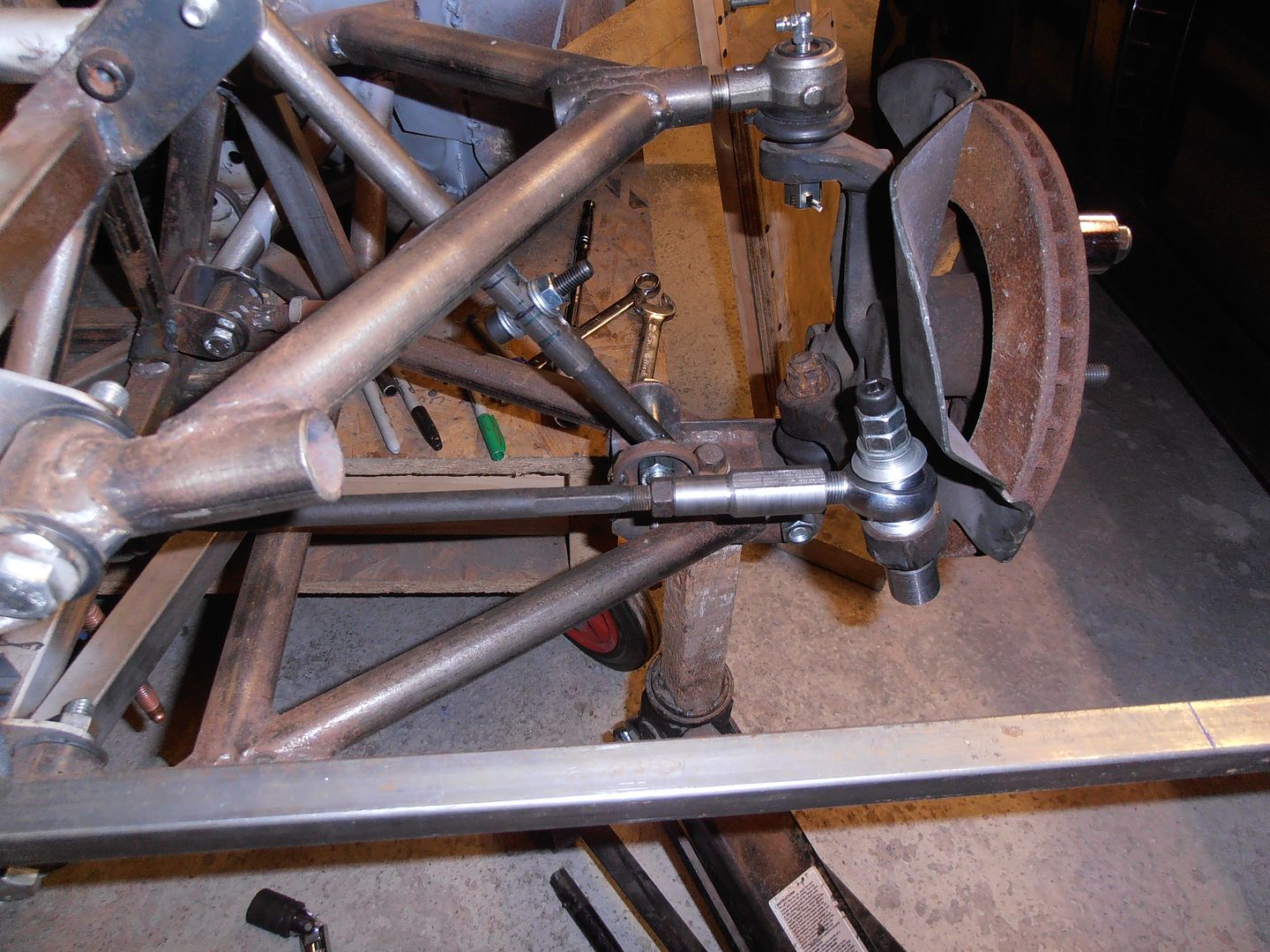 End result is pretty minimal toe change over the normal suspension range, with some increase of bump steer on extreme compression (which would require the bump stop to have collapsed completely (so a bit unlikely movement scenario). i'm pretty happy with the location, so onto designing the proper rack mount. This will be a few mm lower than the measurements so there is +/- shimming room should I make any changes to castor etc. CAD modelling. 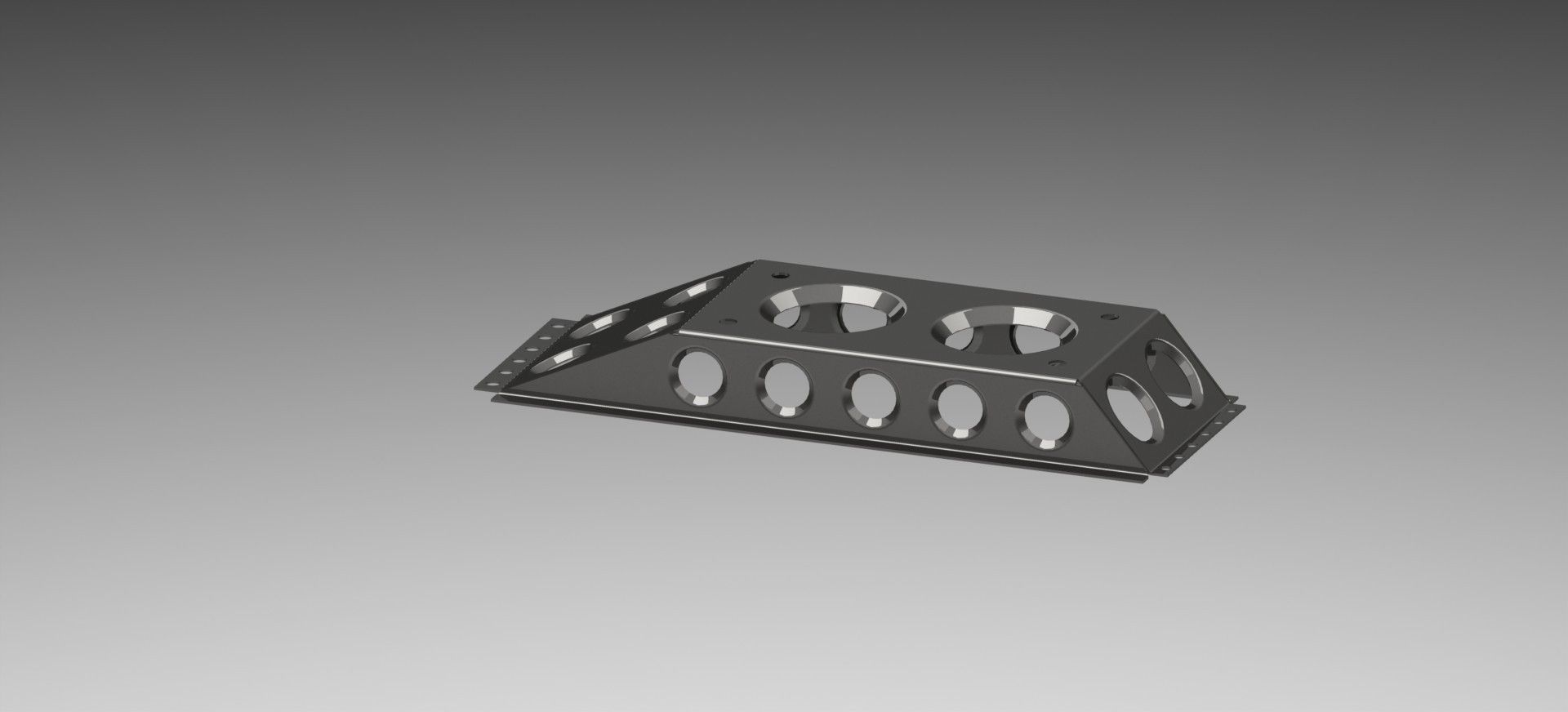 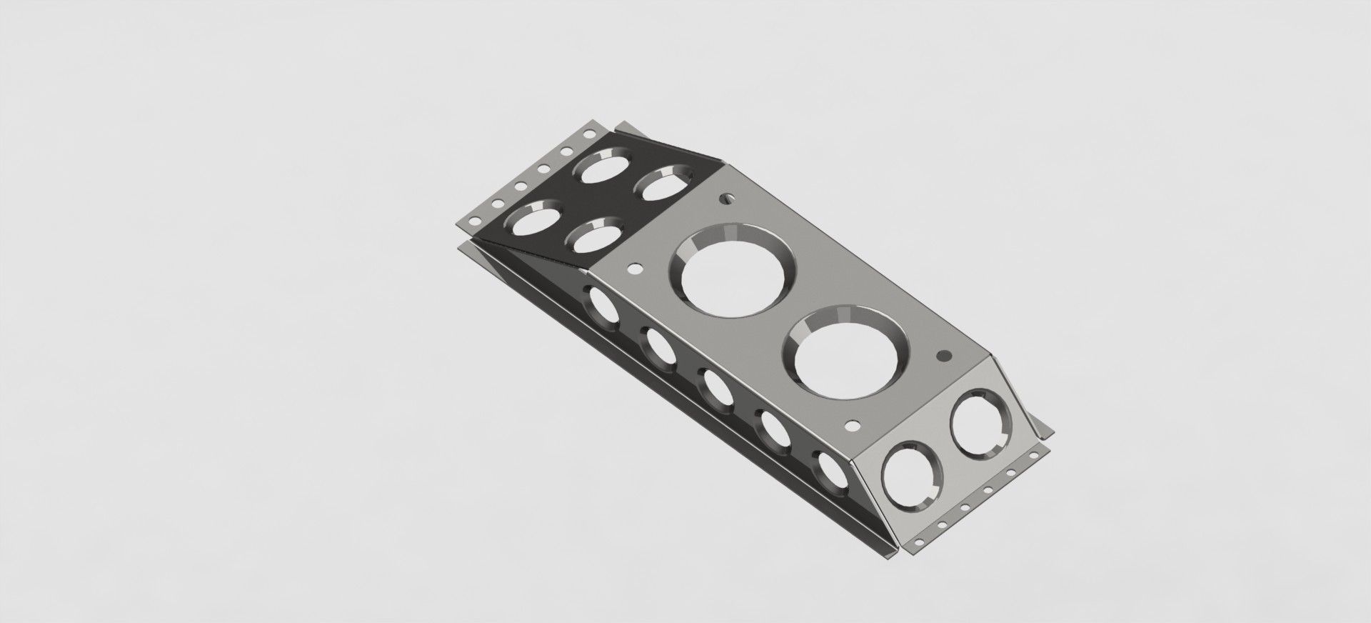 whats handy in the CAD package is that the sheet metal parts can be unfolded.  I can then do a drawing, print it out full scale, and I have a bend and cut map :-) In situ, it'll look a bit like this. 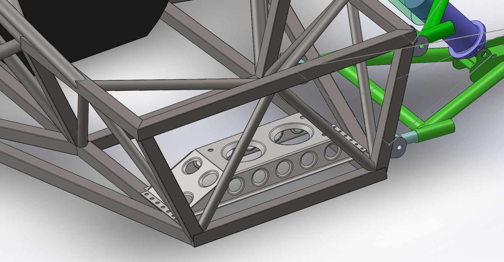 I have to decide now if I want to fab it from tube of from sheet like the mockup above. |
| |
|
|
|
|
|
|
|
But... sheet would make for more speed holes?  |
| |
|
|
jonomisfit
Club Retro Rides Member
Posts: 1,790
Club RR Member Number: 49
|
|
Jan 10, 2016 20:23:24 GMT
|
You make a valid point there Varelse. Spent a bit of time in the workshop today. I don't have a plotter so had to print off the full scale drawing in sections  so I can piece them together into a single drawing. 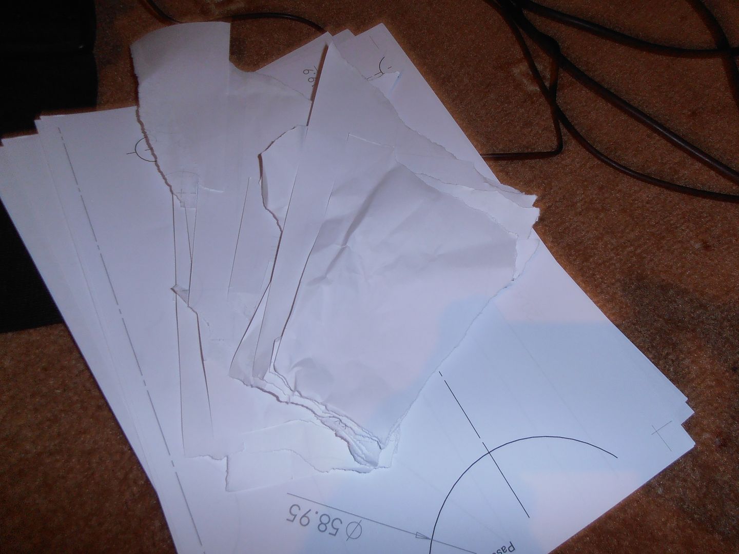 Printer scaling issues..... 3rd times a charm 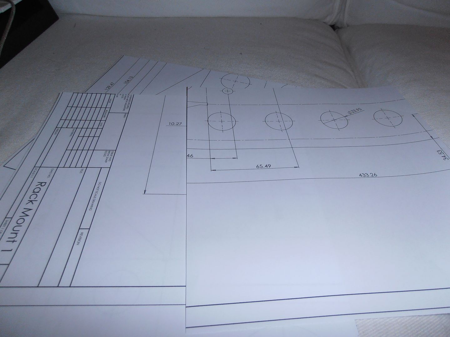 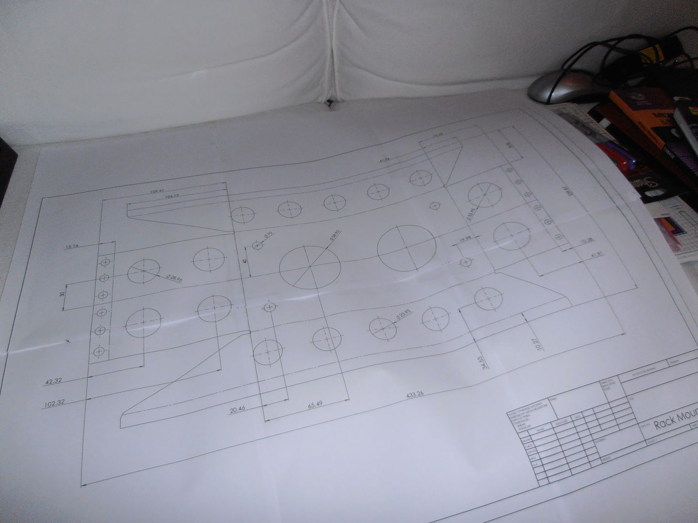 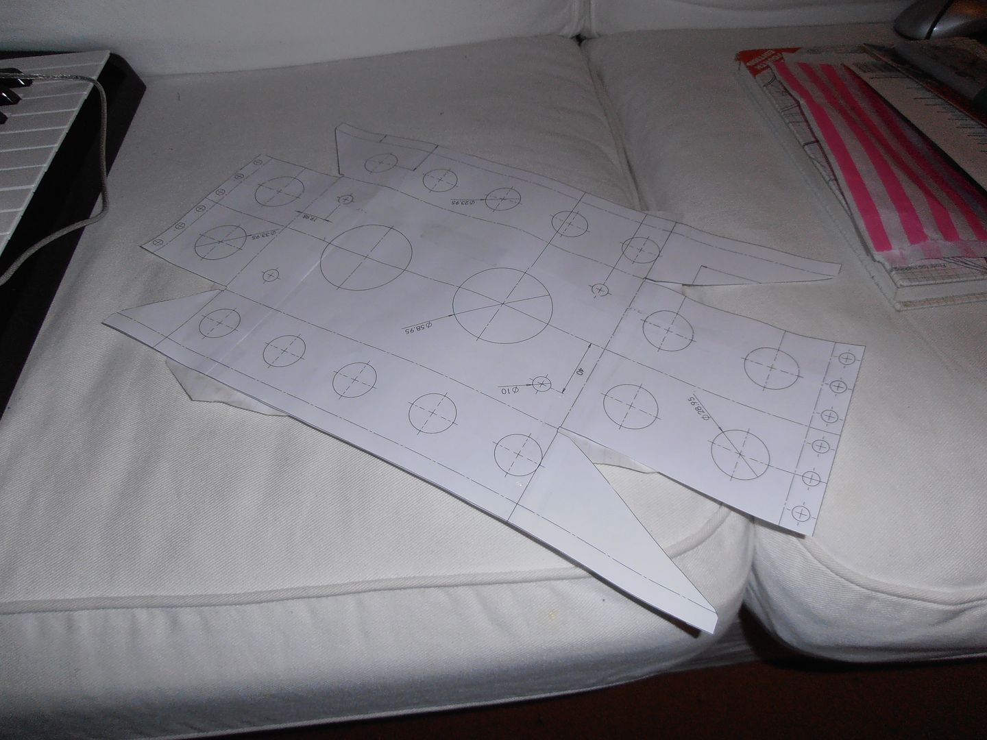 Then glue onto a piece of 1.5mm sheet 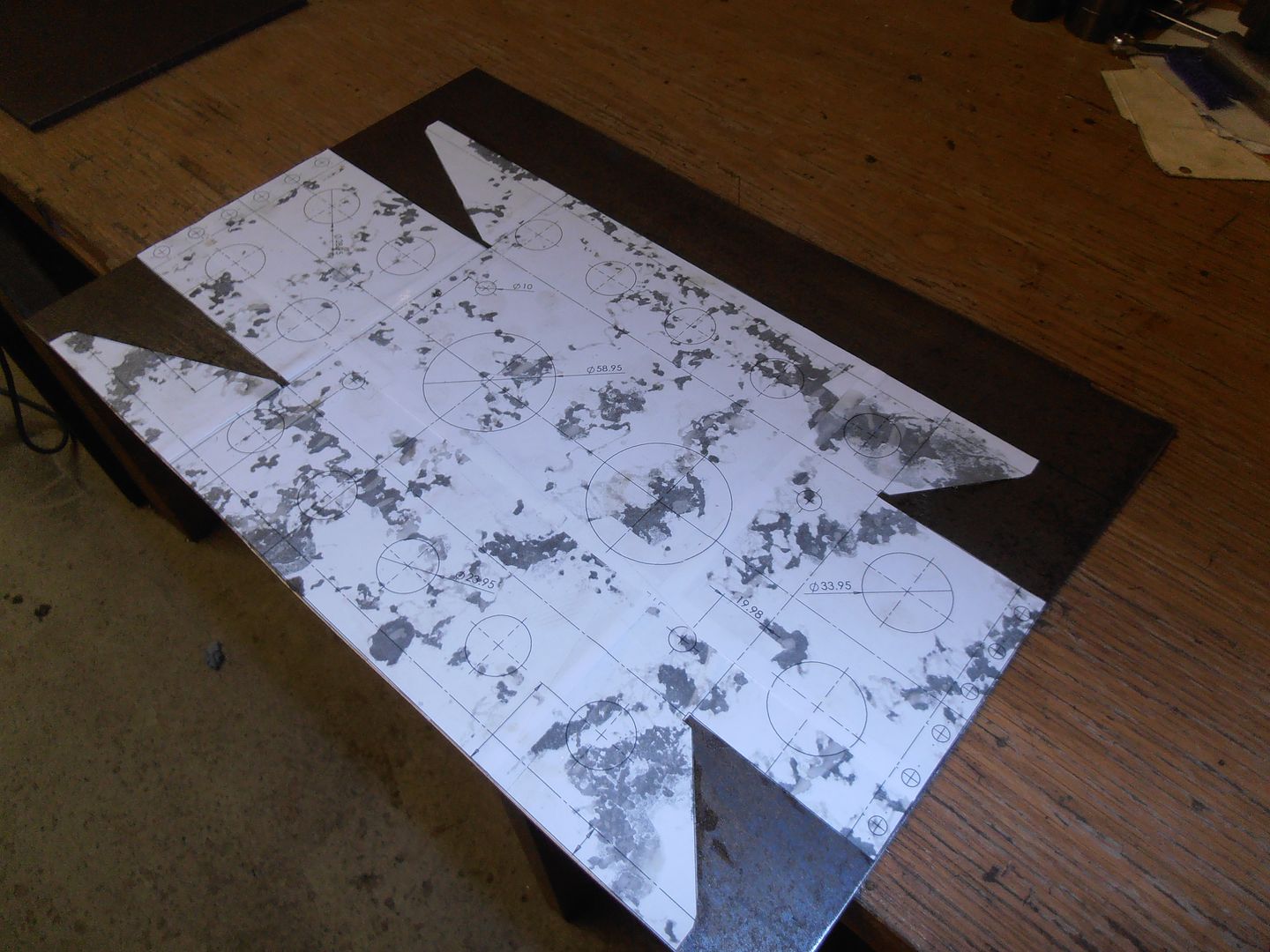 trim to size. Cutting 1.5mm sheet in my sheet metal shear requires much much jumping up and down on the bar. 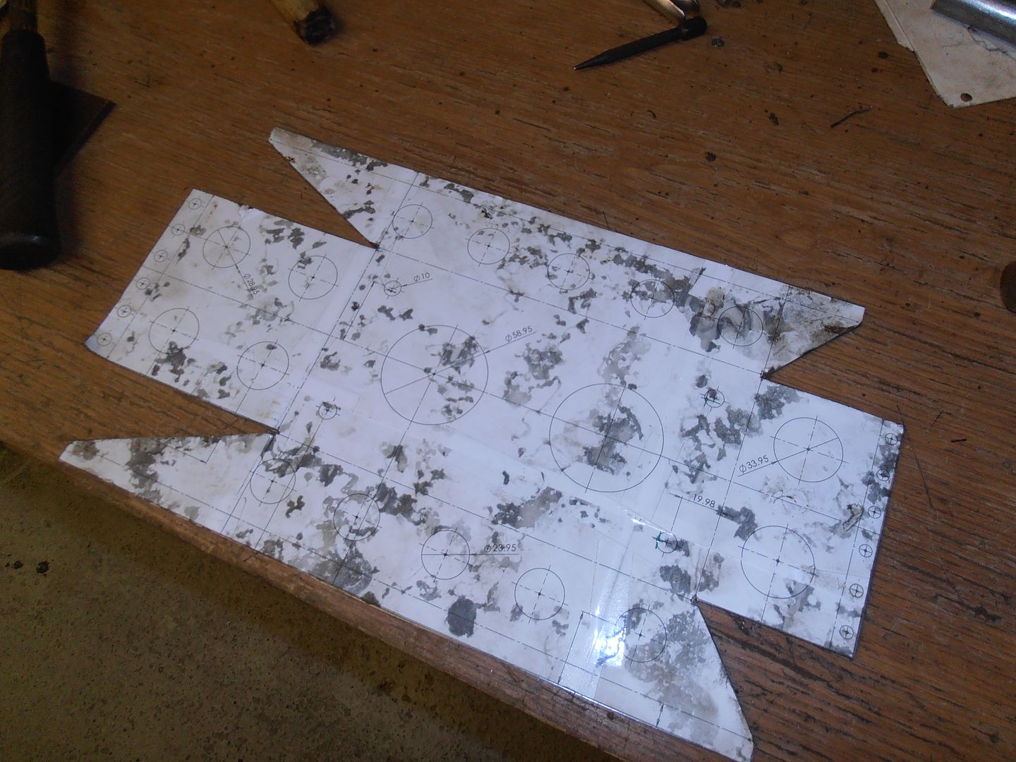 and commence the hole cutting 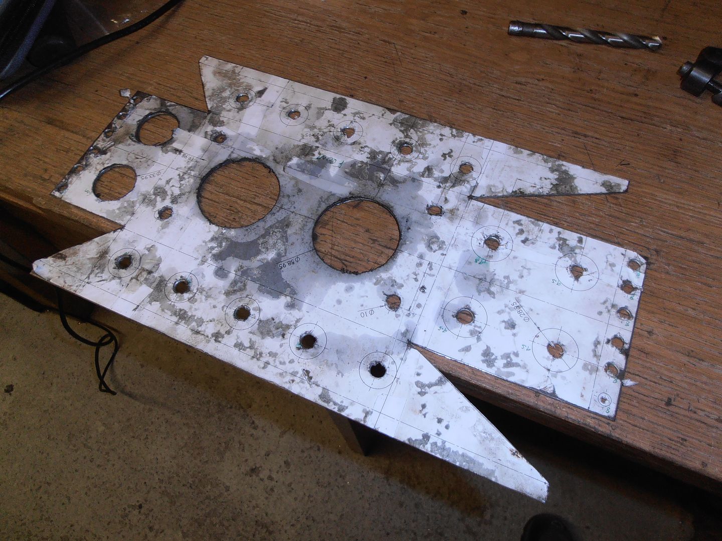 and more cutting 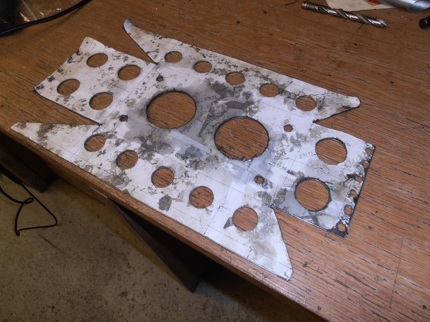 I had to use hole saws for the larger holes as I don't have a q-cutter the right size. I set the milling machine on slow and applied a load of lube. They cut surprisingly accurate holes. and begin folding. 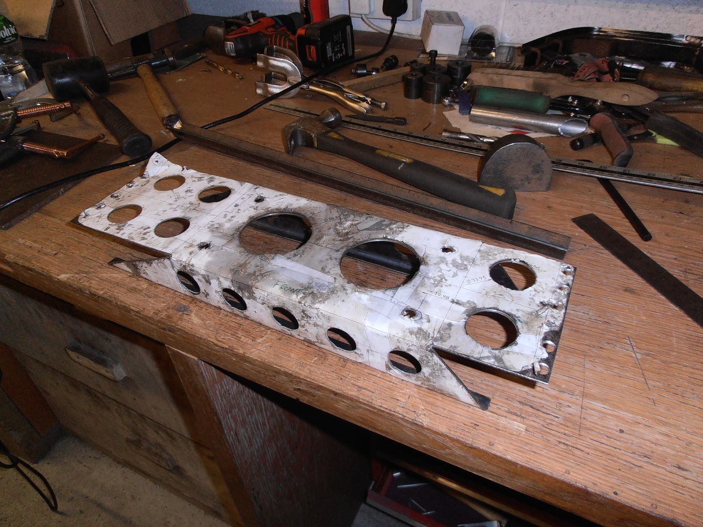 This required me to mod my home made bender with additional clamp bolts as it was flexing a bit and starting to change the bend rad with it 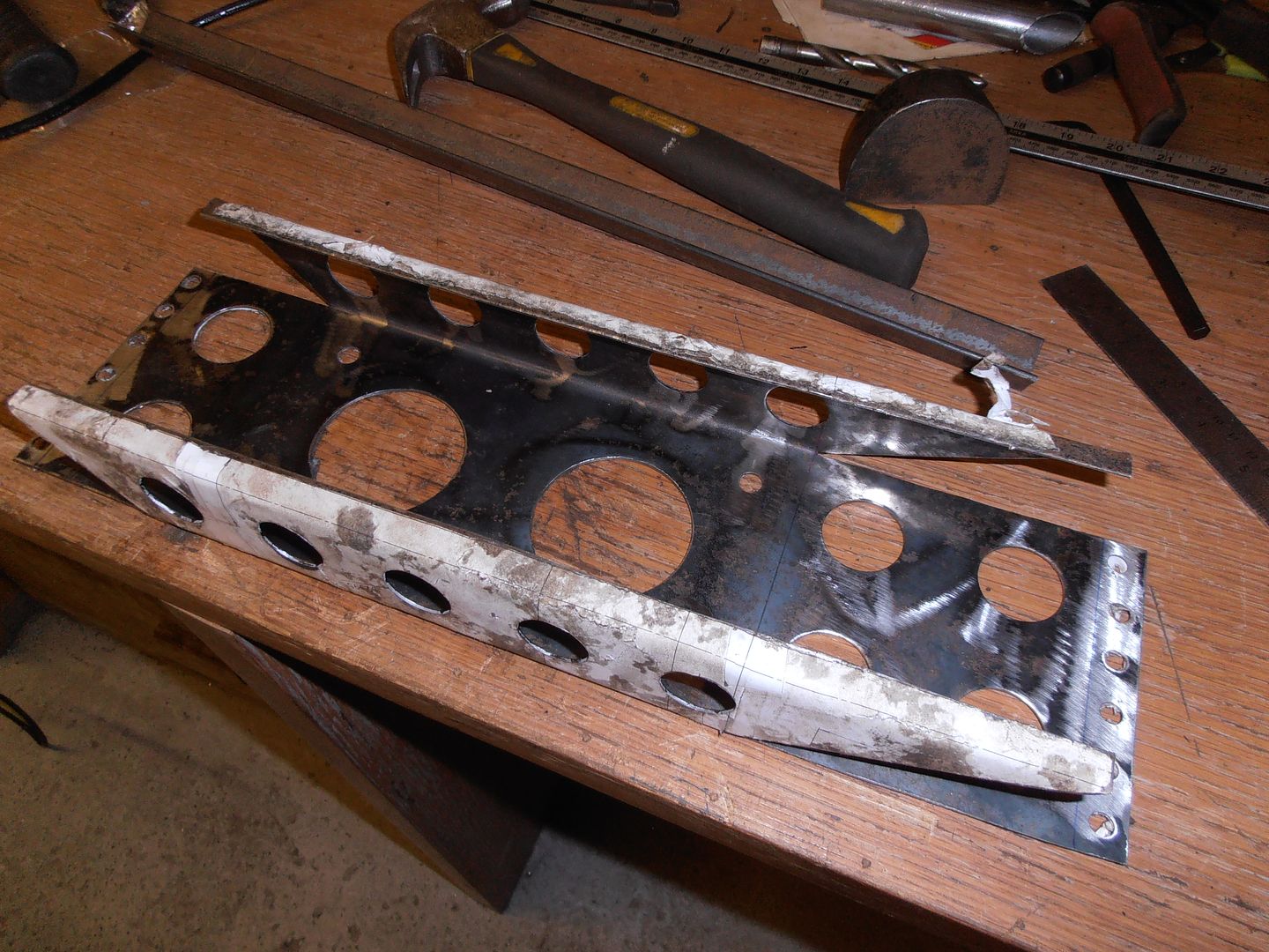 the second double 90 bend was completed partially in the bender and then completed using hammers... 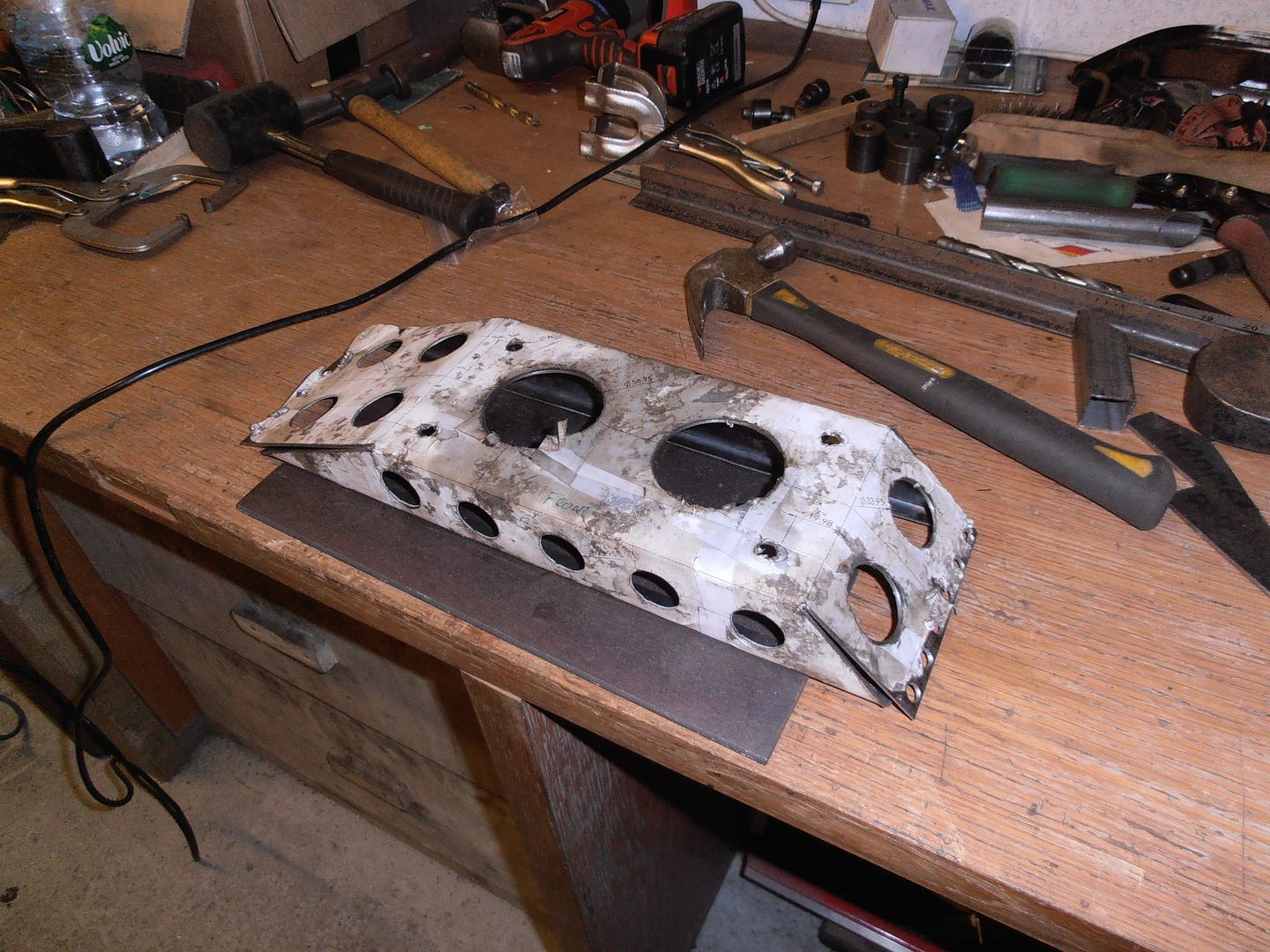 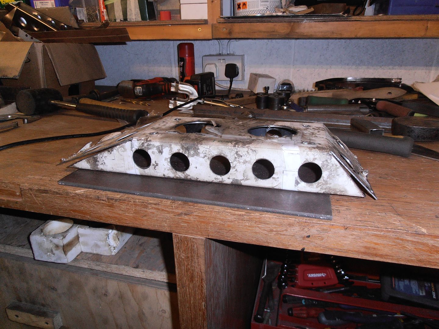 i then tacked it all together to check it, and removed the paper cut template. 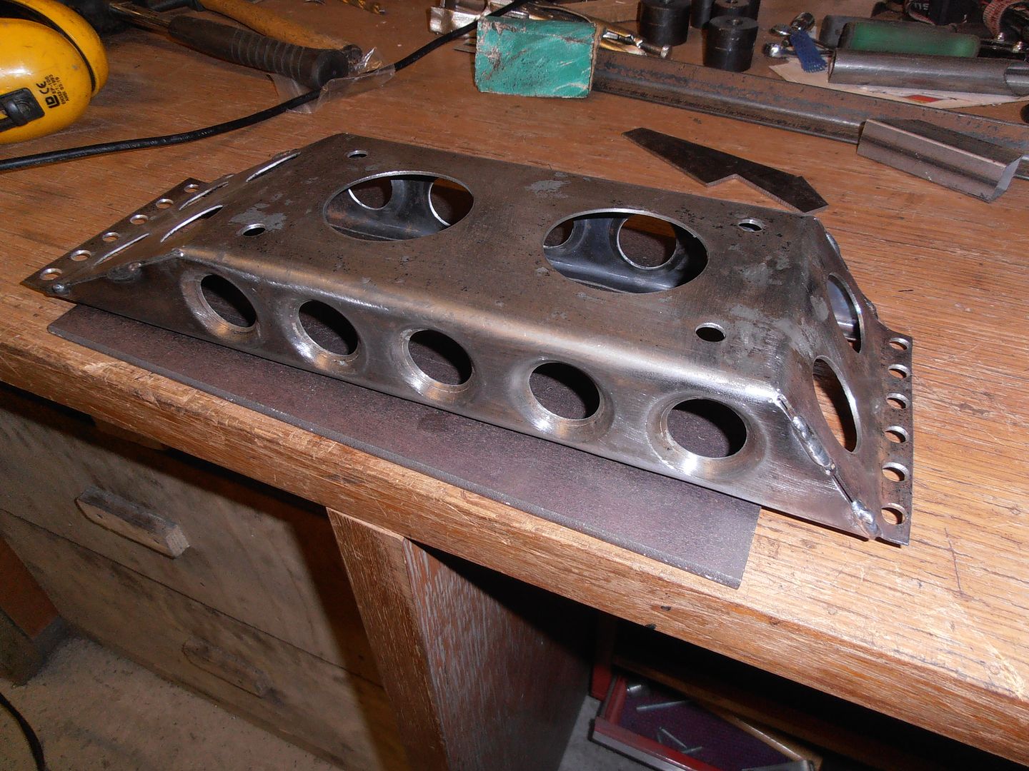 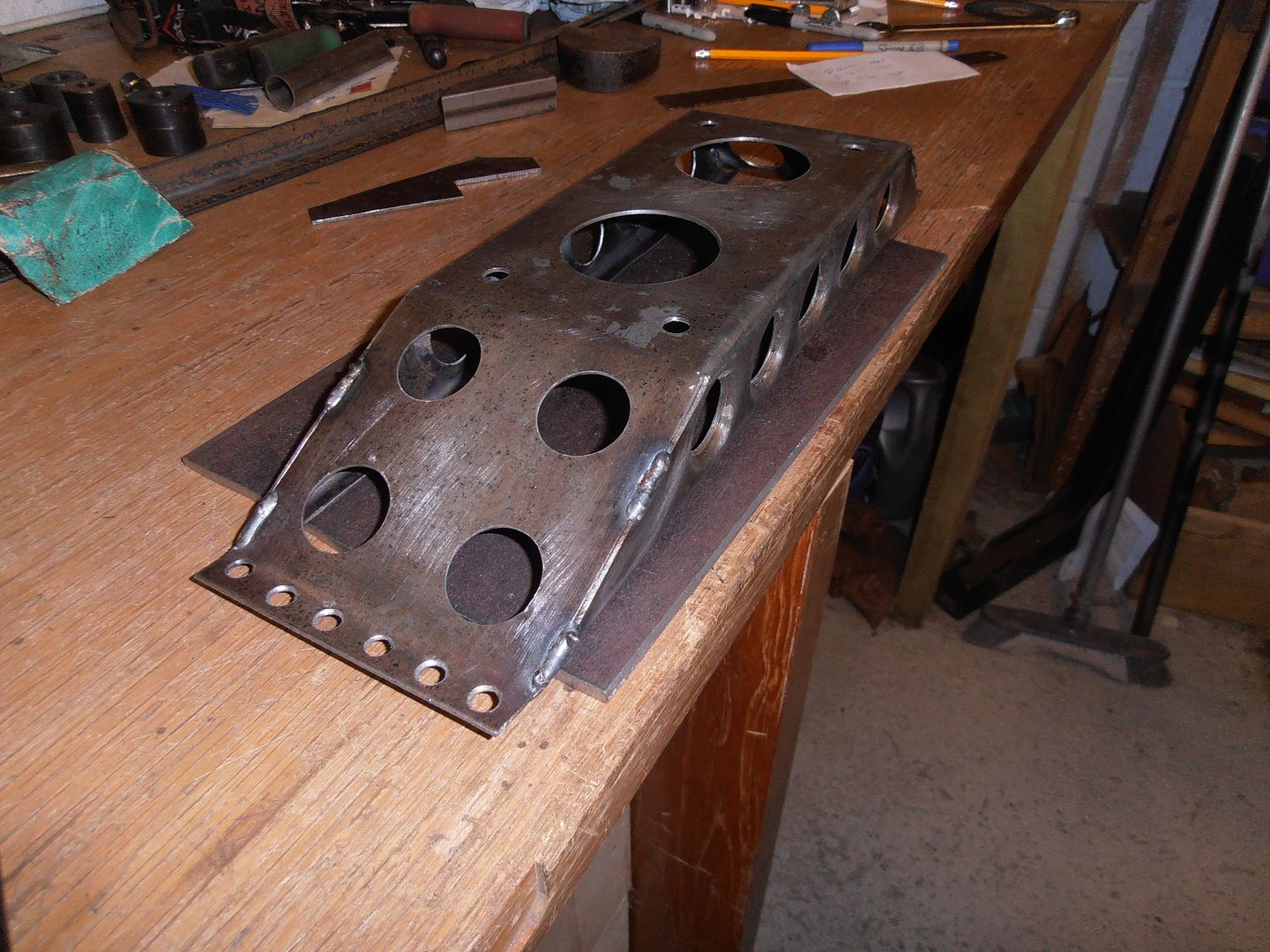 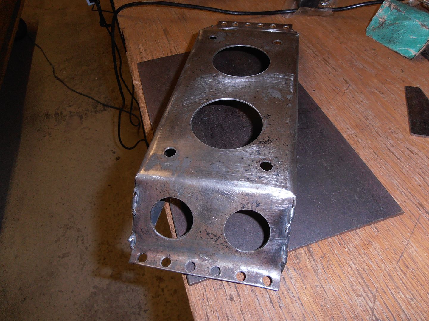 I now have the issue of having to make new swage dies to suit the larger holes (i only have up to 25mm diam). Biggest to do is 64mm hole, with the others 32mm. I've modeled them up and completed a drawing. Getting the right size piece of stock is expensive, so I think i'll probably get 10mm thick pieces of steel and laminate them together. Then I can turn them to he right size. 10mm thick offcuts rounds (basically waste hole center sections from laser cutting holes plate) are cheap and will do the job. Better get designing. |
| |
|
|
jonomisfit
Club Retro Rides Member
Posts: 1,790
Club RR Member Number: 49
|
|
Jan 17, 2016 18:13:46 GMT
|
So, I ordered the correct pieces of steel I needed, but unfortunately they didnt turn up on friday. Yesterday was dry (and freaking cold) so put the other car outside and started on the arch infill panel. 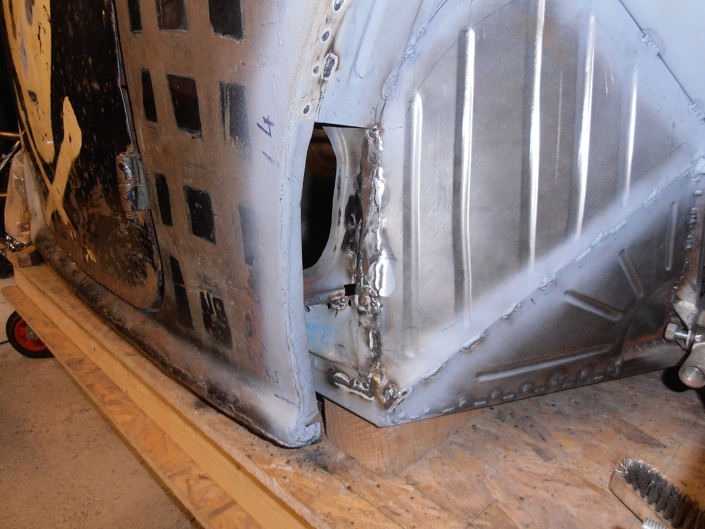 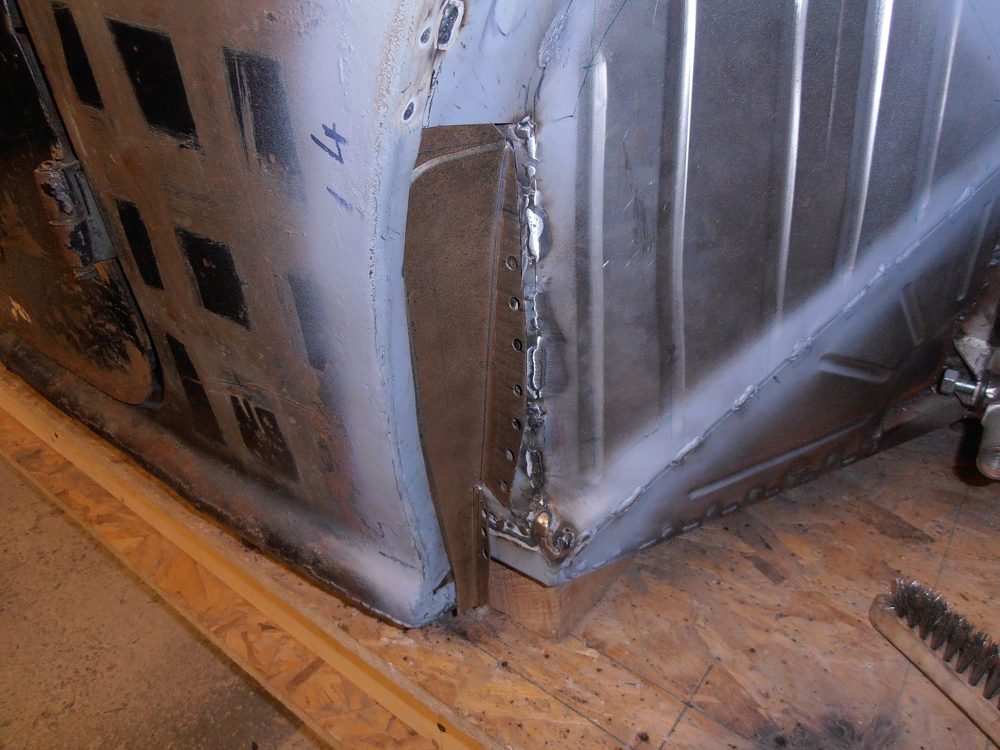 and got that closed off. 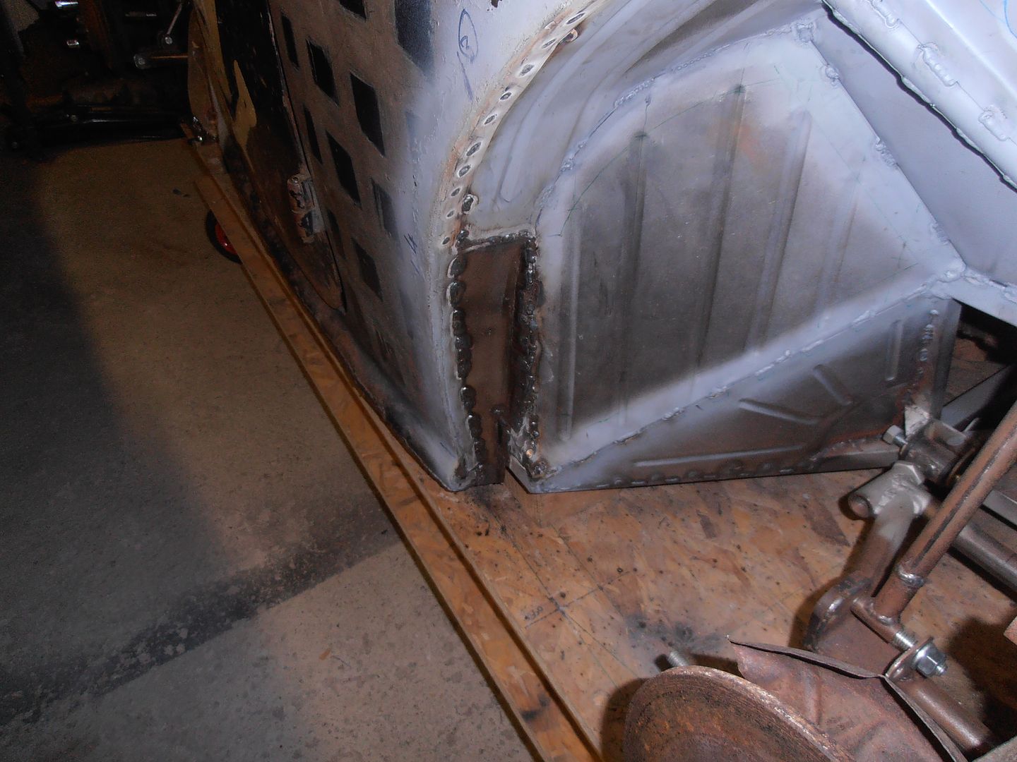 It then started snowing and got colder, so came back in the house. I'm getting pretty fed up moving the bead roller and shrinker / stretcher round out the way all the time so designed a stand. 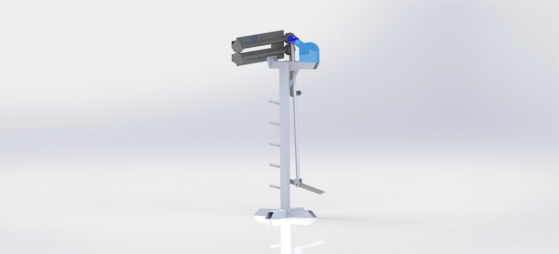  mainly so I can set it up out the way and not have to keep putting it all in / out the vice. Started on it today. Upstand made from 50mm box 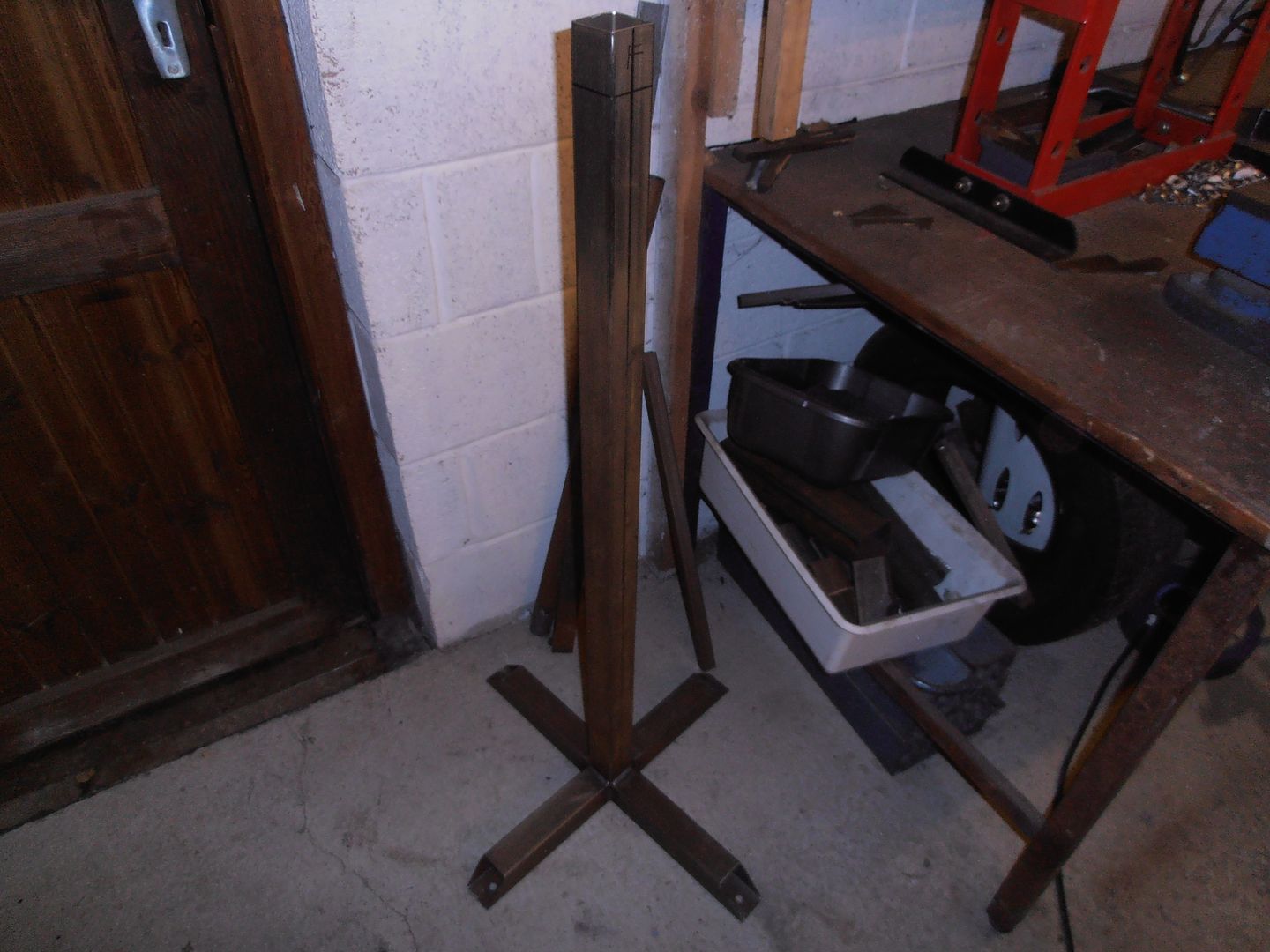 feet have bolt holes should I want to bolt it down shrinker mount started 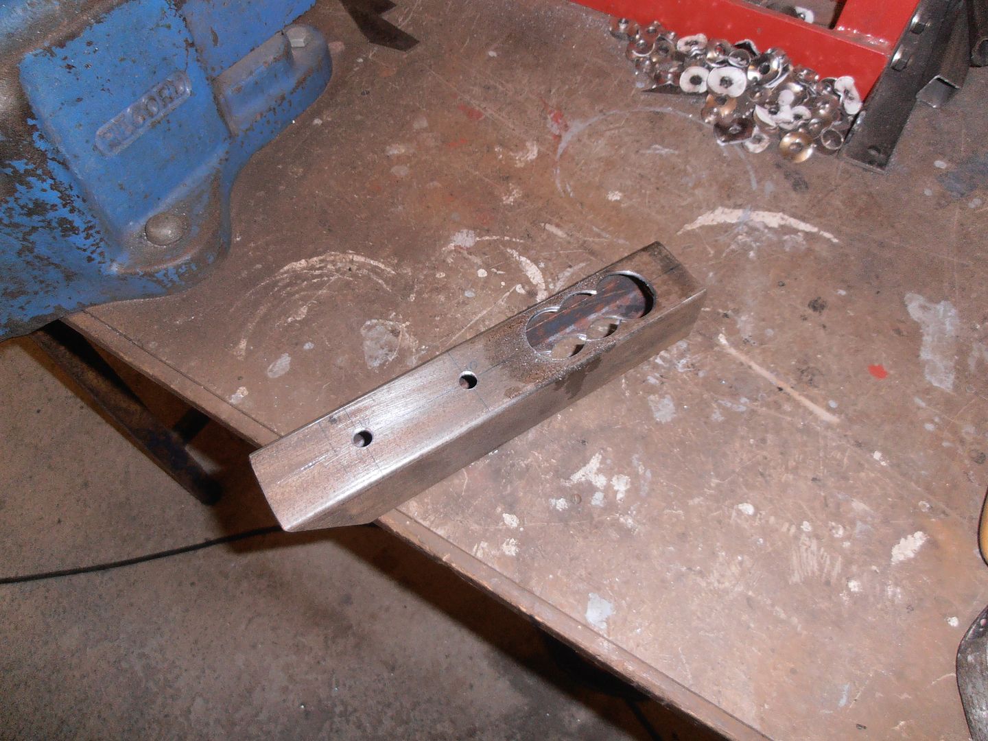 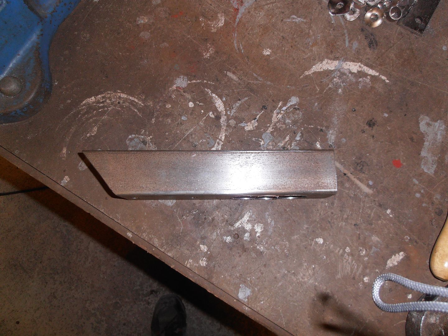 The slot is for the pull rod for the foot pedal. Cut with the hole saw, then finished with the mill.  Tacked into place, along with the mount for the bead roller. 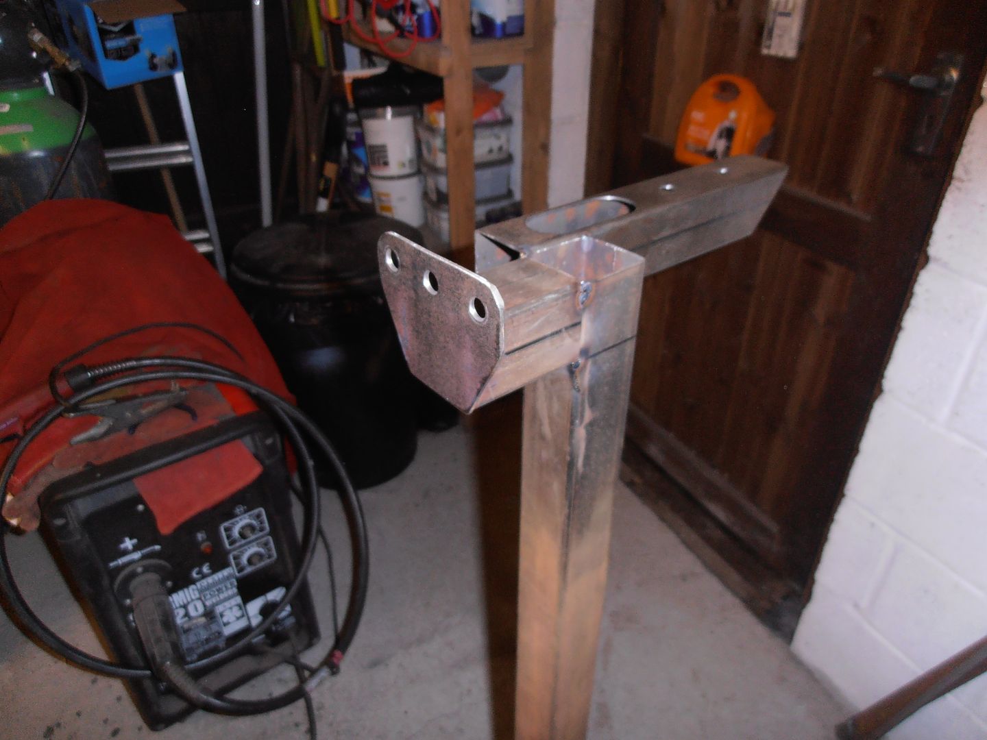 drill the mounting holes on the bead roller. The plate is 10mm thick with 6mm box behind it. 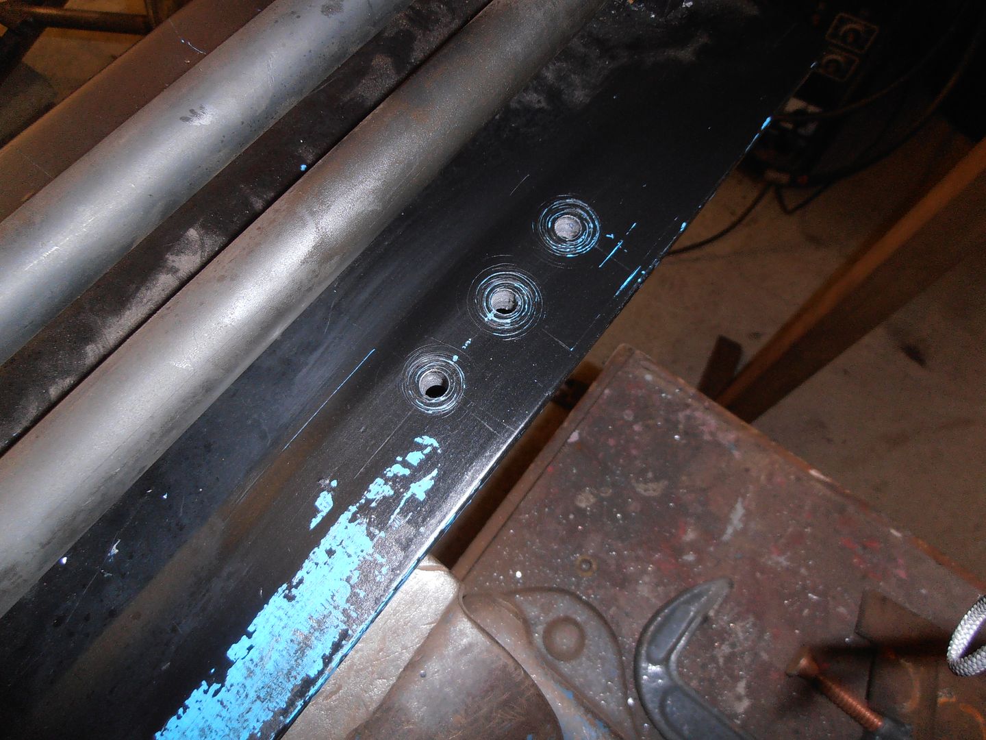 So i've tapped it directly. 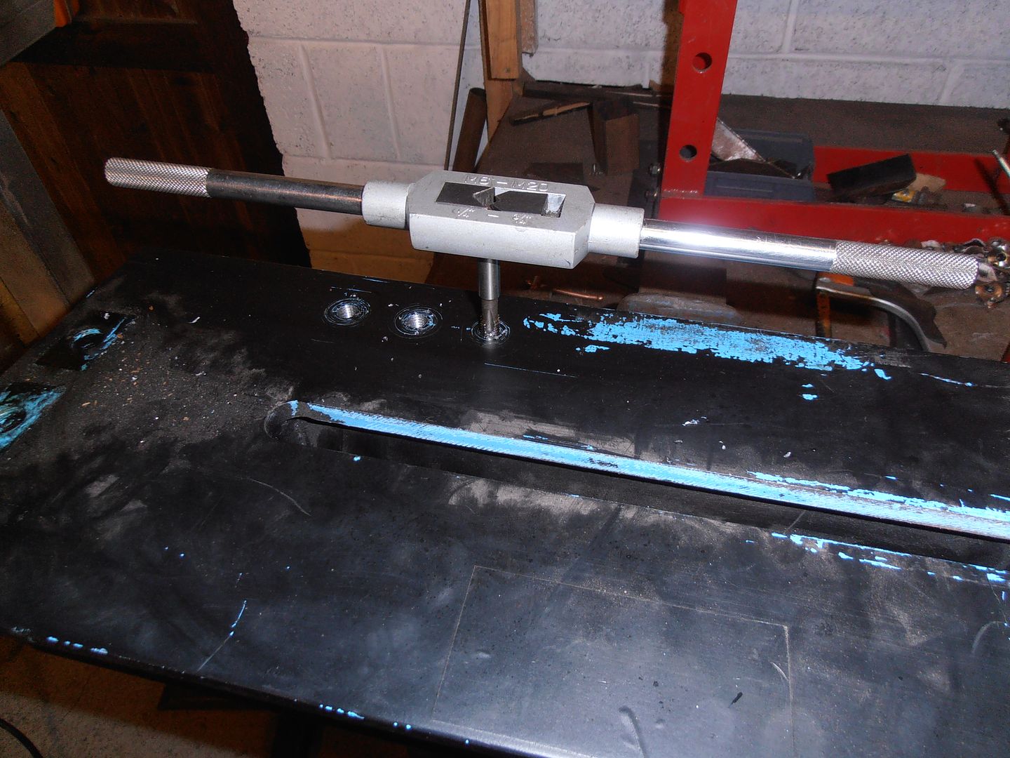 Trial fit 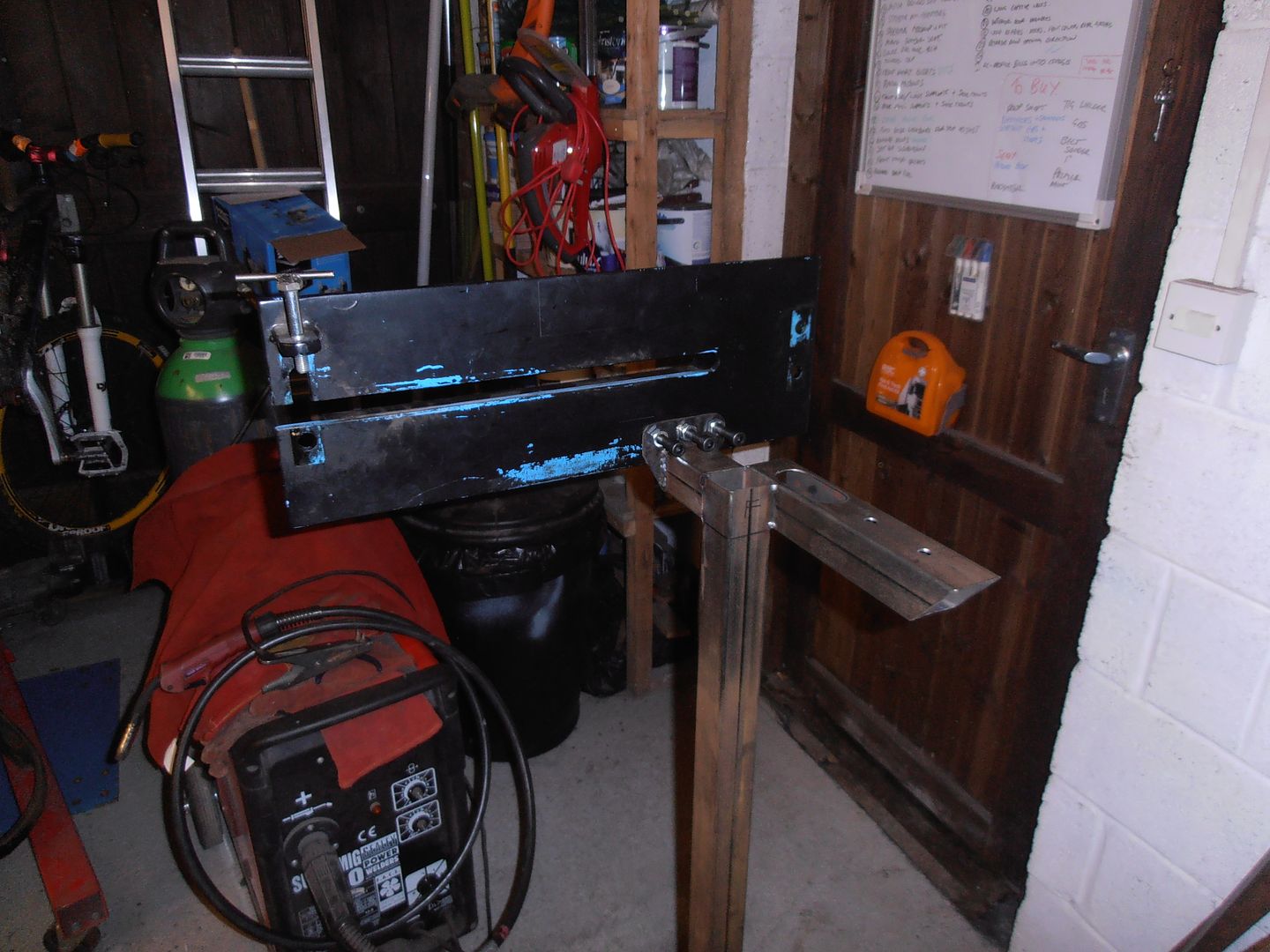 and shrinker trial fit 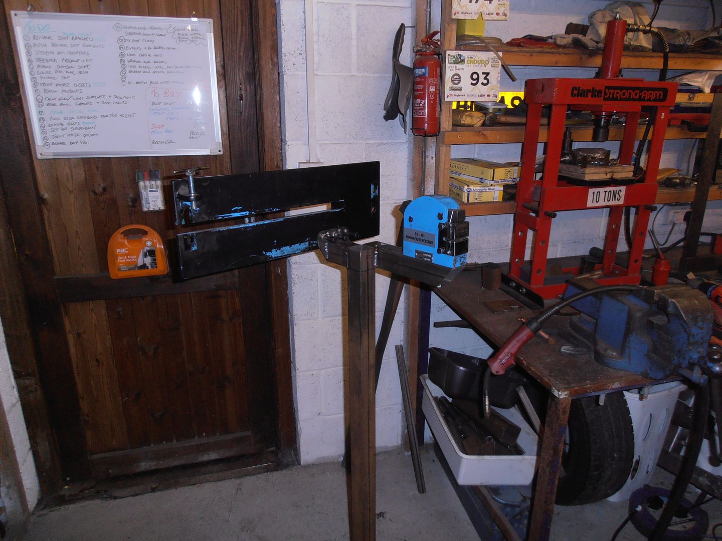 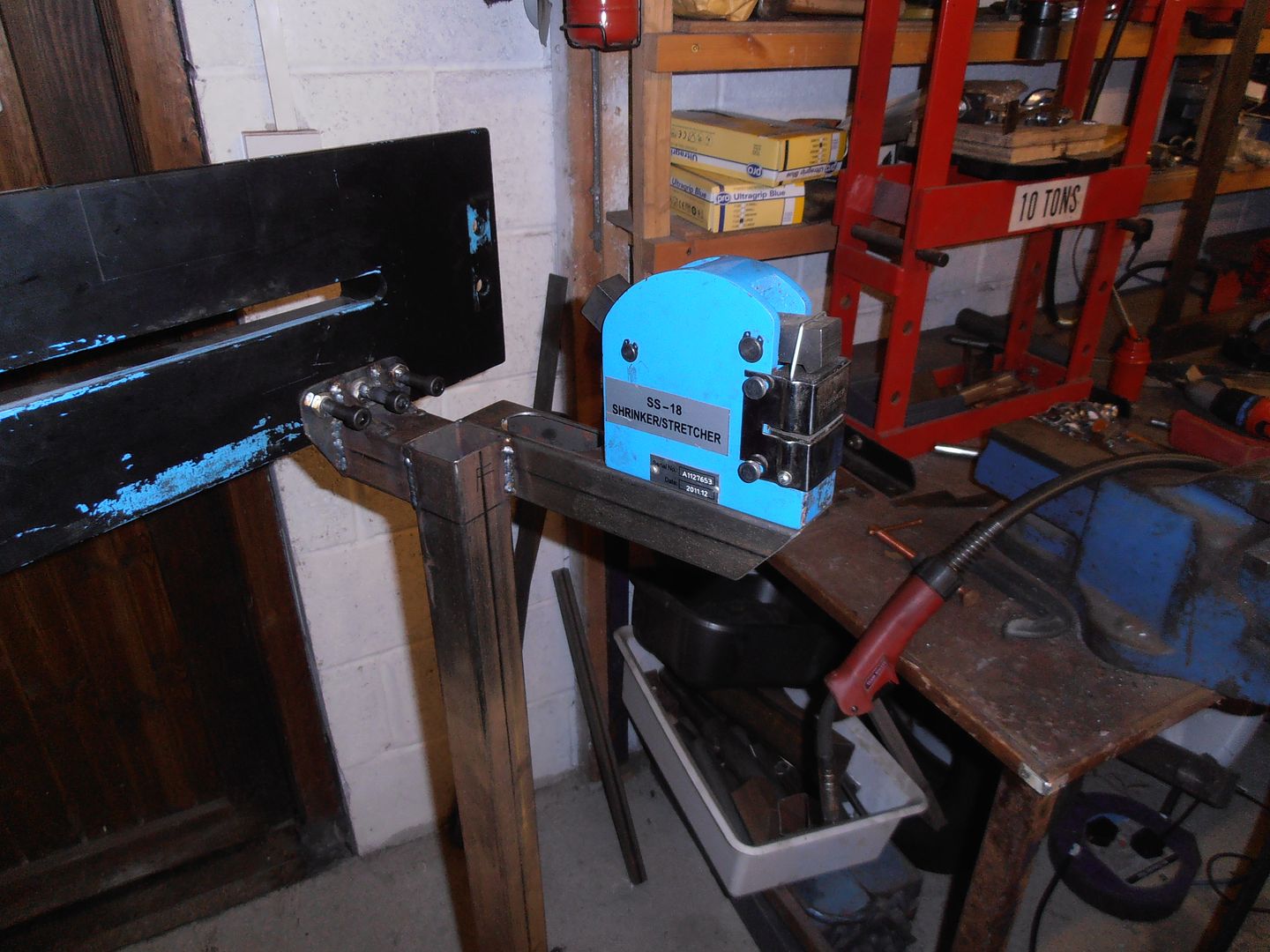 Next session will be the foot pedal and pull rod, although i'm busy the next few weeks so not garage time :-( I'll also probably fit stiffeners from the end of the feet (19mm or 25mm box) to the top, to ensure it doesnt vibrate in use. |
| |
|
|
|
|
|
|
|
|
wow, really cool work on that stand....I'm very jealous and would love a bead roller!
JP
|
| |
I know its spelled Norman Luxury Yacht, but its pronounced Throat Wobbler Mangrove!
|
|
jonomisfit
Club Retro Rides Member
Posts: 1,790
Club RR Member Number: 49
|
|
Jan 30, 2016 21:12:08 GMT
|
Operation complete the steering rack bracket re-commences My rounds turned up so was able to make a start on the press tools. Using the internal jaws on the 4 jaw chuck drill a center hole in all three pieces of the male half of the press tool. 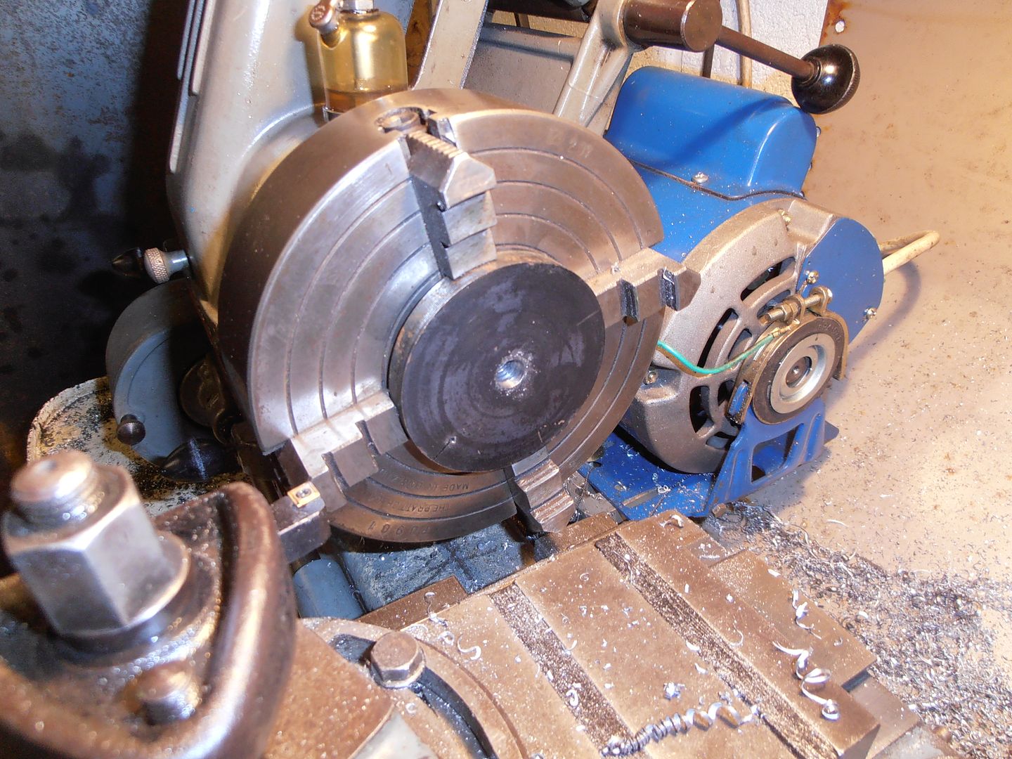 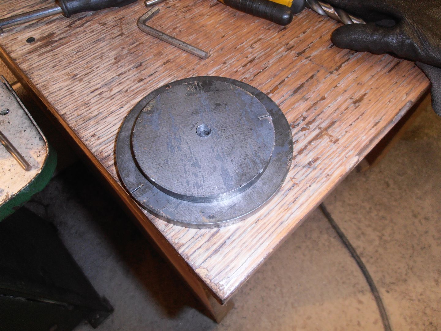  I bolted them solidly together and scribed a line for the two m8 cap head bolts 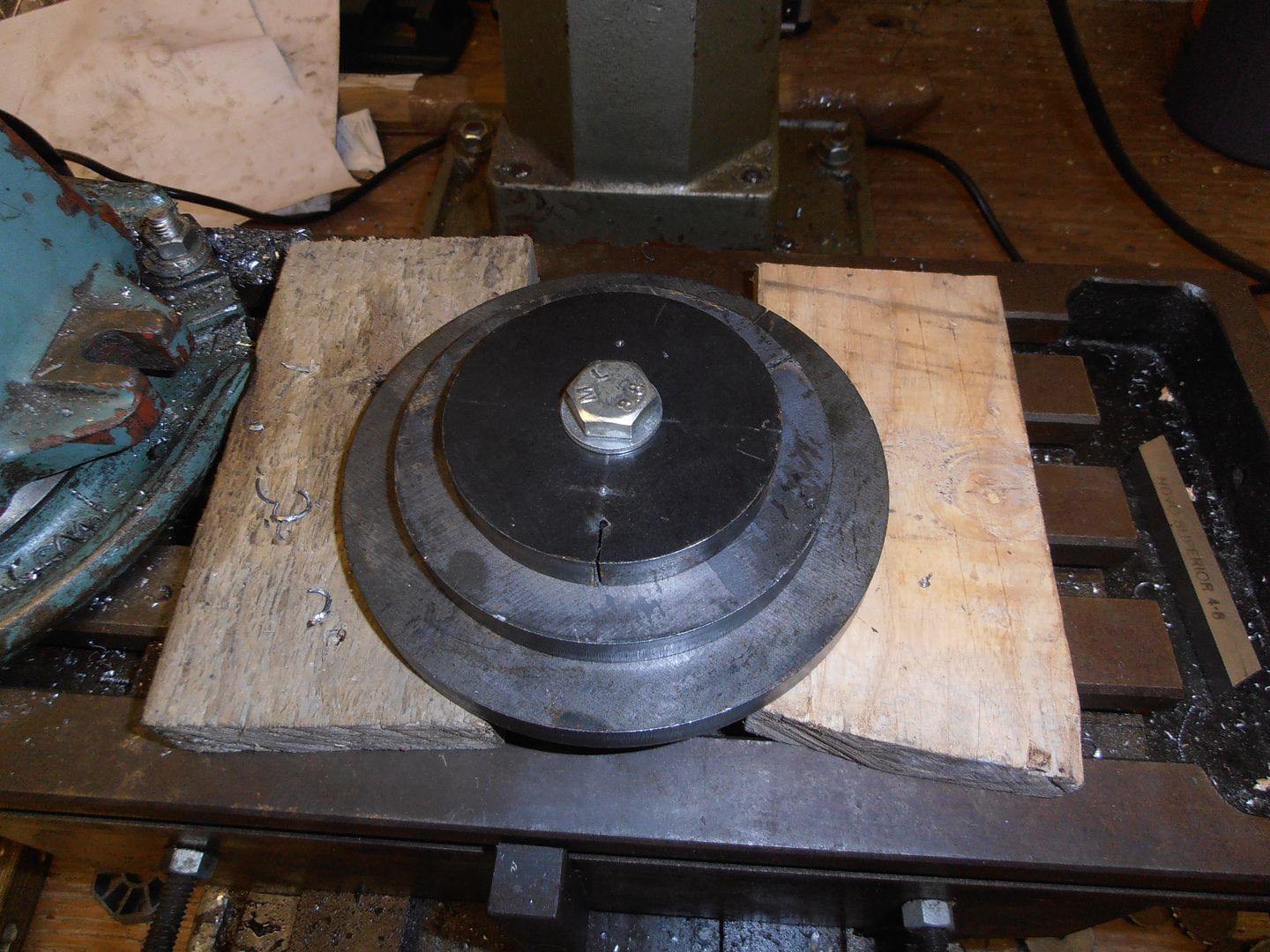 drilled through the first two plates and tapped the back plate then bolted solid 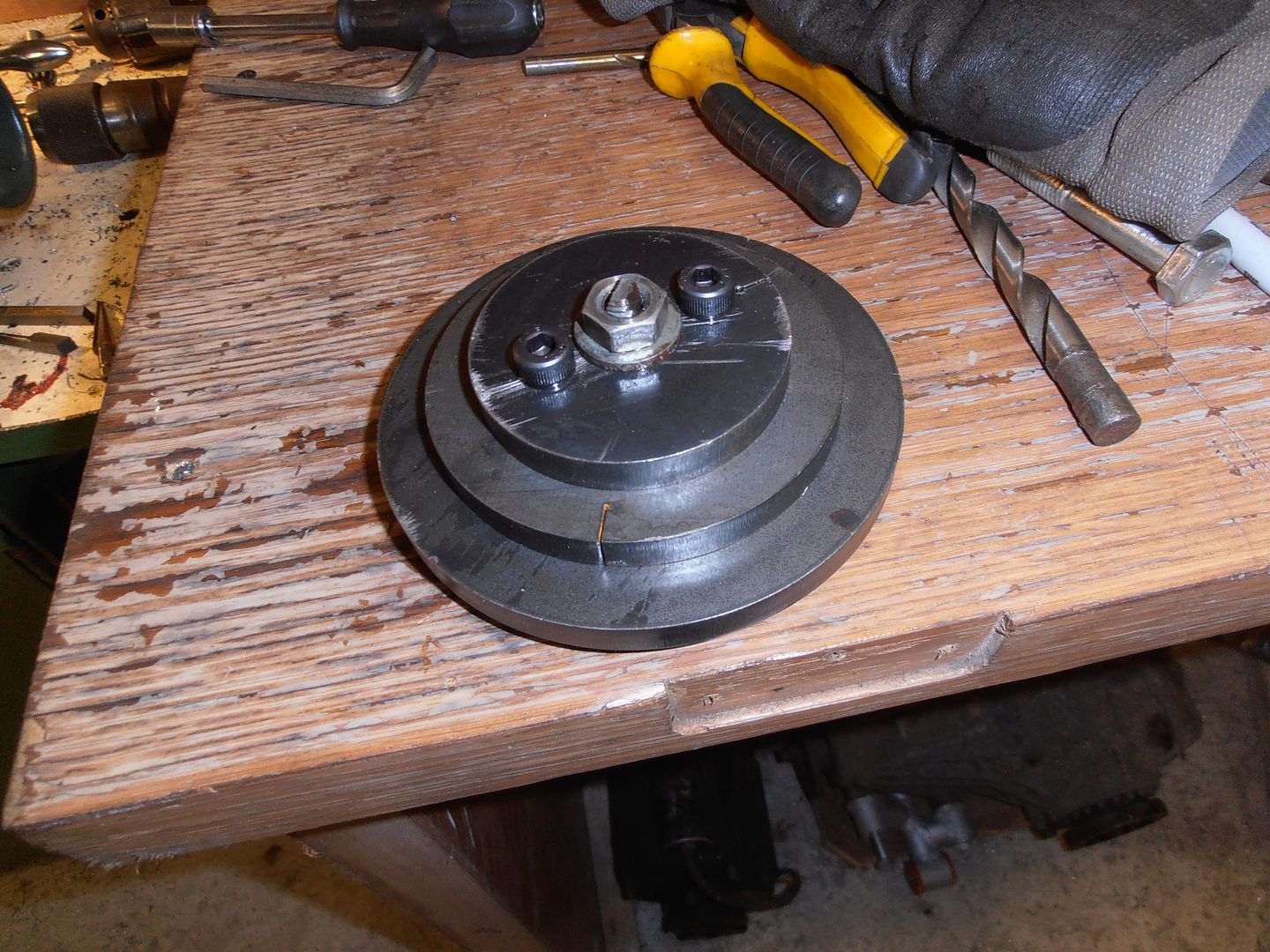 then center back in the late so I can start turning the taper 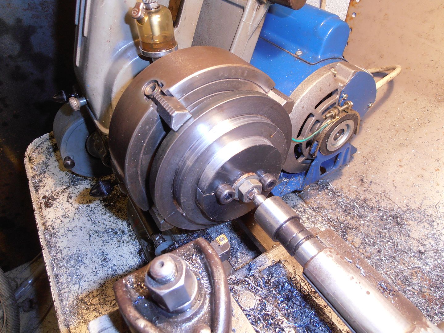 turn all to size and cut the angled section   male half made. Onto the female half cut a starter hole in the round. 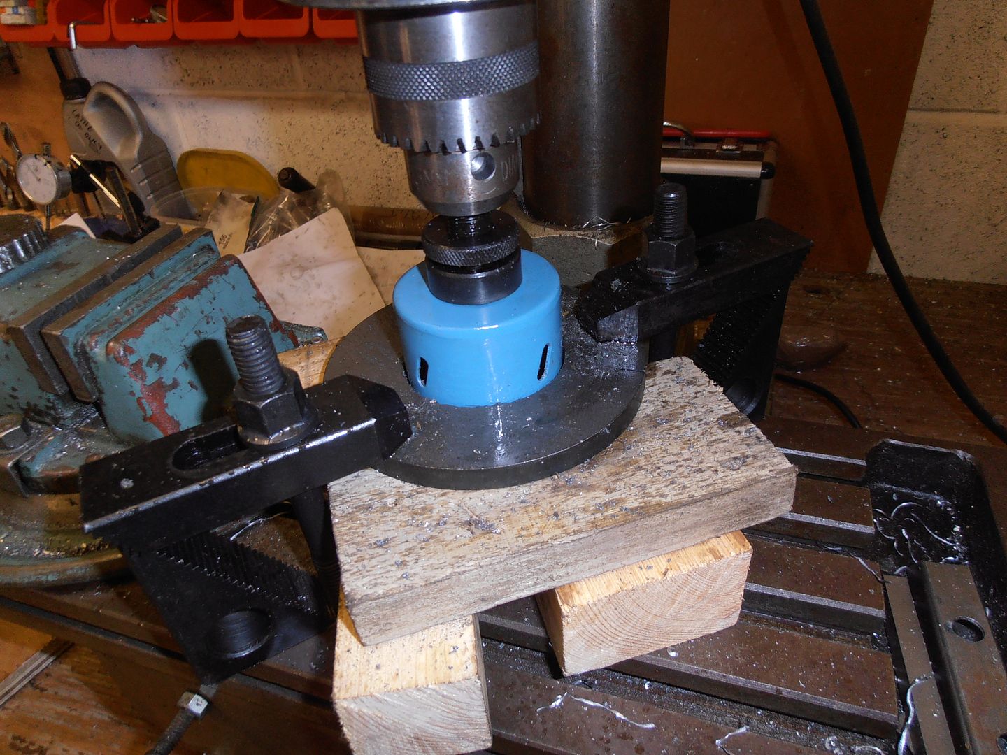 to make it a bit easier for the hole saw / drill i did a chain drill all the way round first to reduce the amount to be cut. clamped it all up and started cutting  took about 10 mins  starter hole 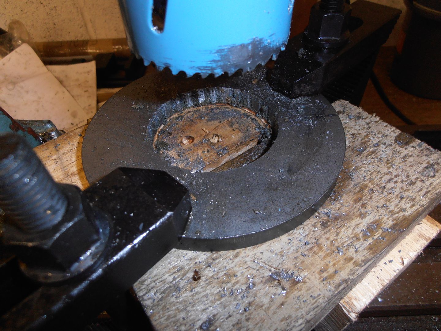 spare piece of blank 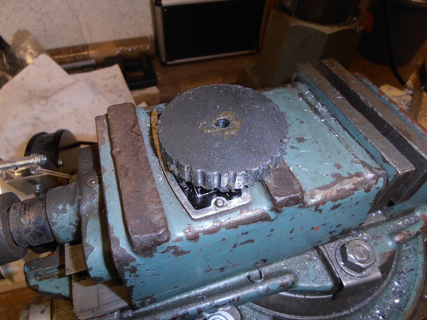 i then scribed a location line (using the lathe and lathe tool) to mark out where the inner piece should sit Clamped and tacked together 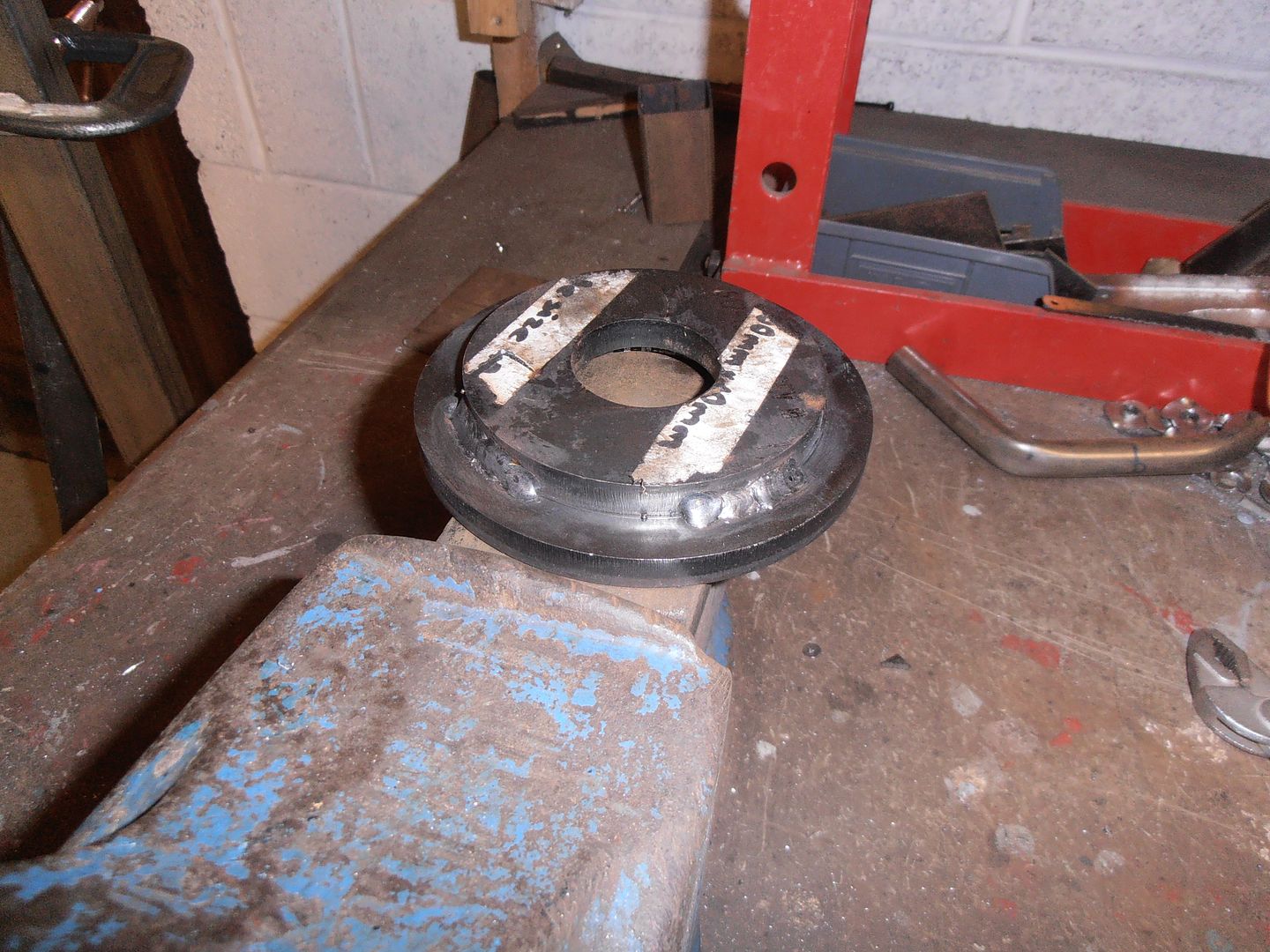 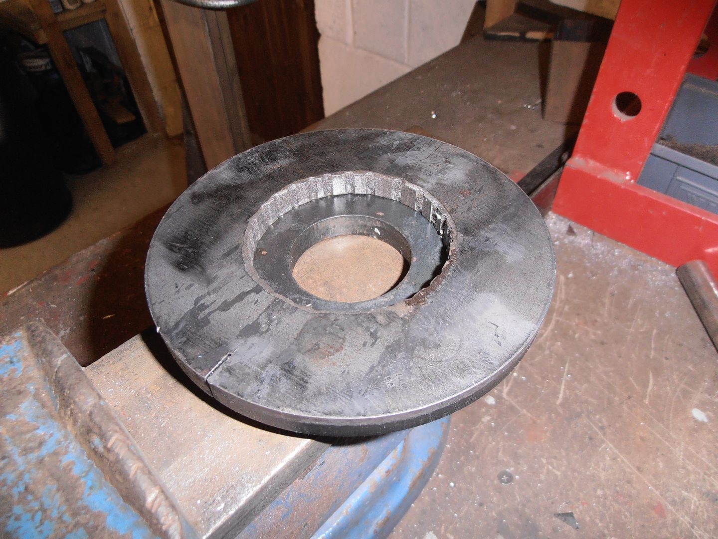 I then changed my mind on center bore size, so its back to chain drilling. 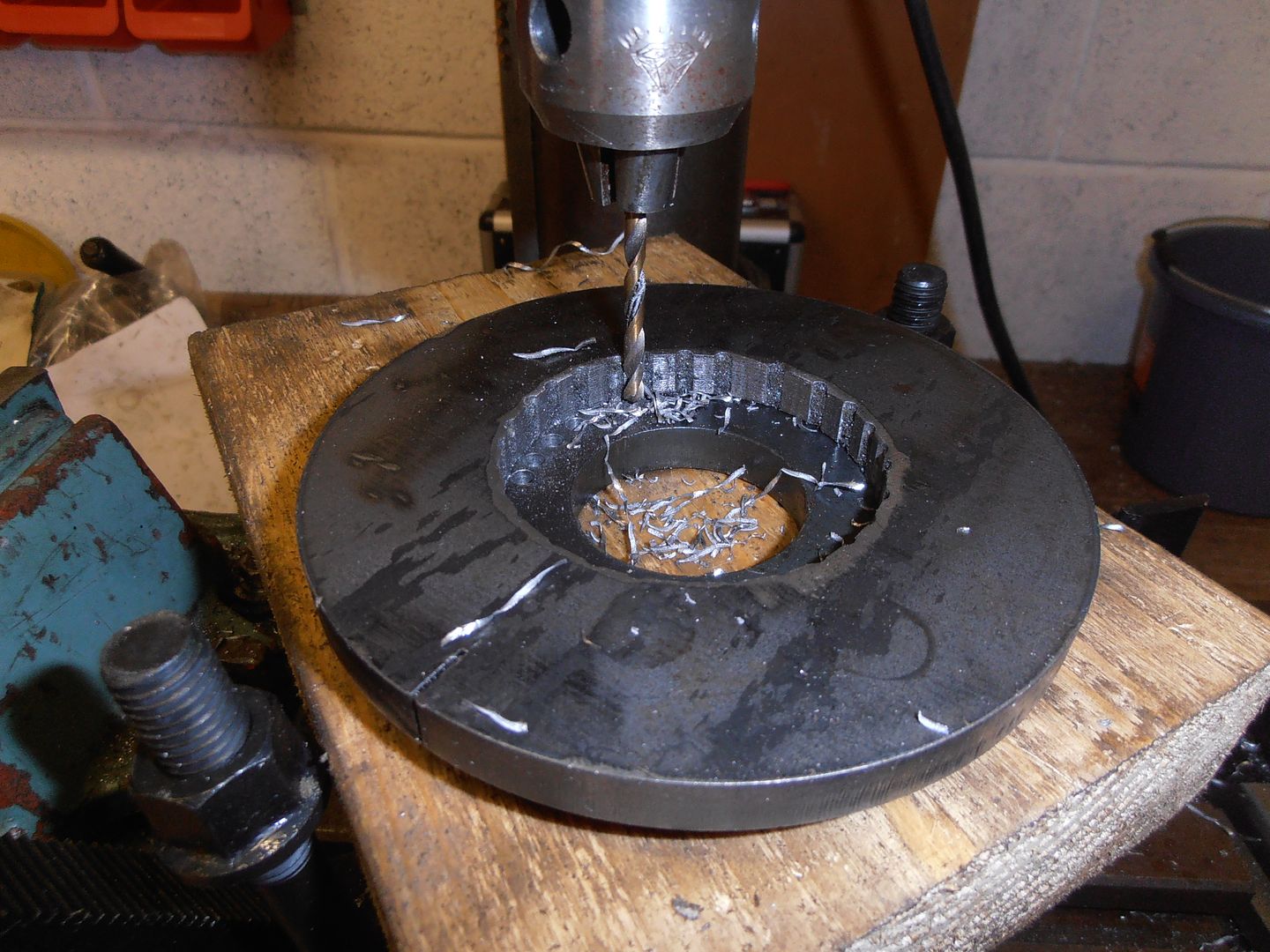 Will hopefully complete it tomorrow. where it'll be a case of bore the lead in to size and test it out. If there's time i'll also be trying to finish the tool stand. |
| |
Last Edit: Jan 30, 2016 21:14:03 GMT by jonomisfit
|
|
|
|


