|
|
|
|
|
Some good stuff going on Bruce, but please....buy the man some safety specs, A&E is a grim place to spend your time! There are a number of pairs of goggles, safety specs etc...around the unit. One thing I can't do is make people wear them. I've had metal filing in my eye a few times now. Not nice! I've never been to A&E though, I just wait until it works its way out (the rusty staining looks quite interesting for a week or so)  Is that the box in for good now? :-D You probably woulda got it done sooner if I hadn't sat in the Landy all day making brrrrrmmmm and wobba wobba wobba noises ;-) Box is currently out. It had only been test fitted so I could build everything around it. It's currently sat on a tabletop awaiting a proper clean and new sump etc...before being refitted. I've got to sort something quite important before I can make any progress with it though  As for you visiting, yes I think I could have got a fair bit more done but it was amusing to see you hopping in & out of the LR like an excited kid! It was the first time I'd seen it in the metal and realised just how low it is and how awesome it looks from the rear!!  |
| |
Koos
|
|
|
|
|
|
|
|
|
Once the shifter cable was in, James and I spent a while adjusting it to give the optimum gear selection although I think I may revisit this and tweak it a bit more once everything is finally in and running. Next step was to fit the kickdown cable. A job I really wasn't looking forward to doing. Mounting it was relatively simple, just a case of bolting the gearbox kickdown cable to the engine kickdown cable...this took all of about 5 mins (finding the right size bolt to join the two cables together) and about another 5 mins making sure the mount was fitted and secure. Once we started testing it we found the throttle was running out of travel before the kickdown came in. The cable moves nice & smoothly right the way through the throttle range (as it should) but there just isn't enough to engage the kickdown itself which should be the last 20% of the throttle movement. I suggested adjusting the throttle stop to see if there was any more travel left. James quickly grabbed the throttle and twisted it, confirming that there was indeed some spare throttle movement left before hitting the end of the travel on the throttle body itself. This meant we could happily adjust the stop on the pedal. Except for one thing...there was no adjustment left! With some team work to get the throttle stop out (me under the pdeal box and James in the engine bay) we fitted a new set-screw rather than a bolt which gave use more room to adjust the pedal and therefore the cable. With some careful adjustments, an hour later we not only had a working kickdown, but also a pedal & throttle that worked fully. Awesome. No photos of this bit though.... Next up I suggested something that neither of us really wanted to do...it was a pig of a job before, but it was going to be an even bigger pig of a job seeing as there were only two of us this time. Relocating the engine. Again! Without going into too much detail I wasn't entirely happy with the amount of thread left when bolting in the new mount spacers previously, so I decided I could sleep happier if we dropped the whole thing by 5mm (originally spaced up 20mm, so now will be 15mm higher than it was when the BW box was fitted) I'd checked the clearance on the bottom of the bellhousing and worked out there was enough room to drop it 5mm and still clear the crossmember. Without further ado we got the engine connected to the engine crane and started hoisting. 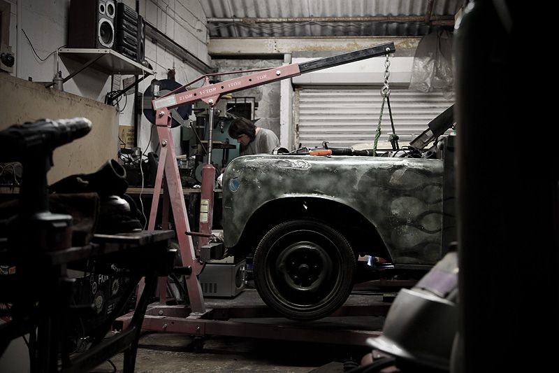 I don't really have any photos from these few hours, but I can tell you we had a pig of a job getting the mounts changed. To cut a long story short it ended up with us somehow lifting the whole engine, and car, and crane on the newly fabricated transmission tunnel (which I'd forgotten to undo!!). It was only after the third time of the car coming up off the ramp and the crane trying to pull itself over that we realised the error. 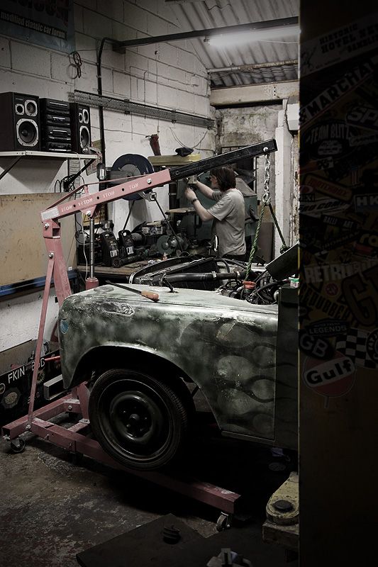 On top of that I ended up with one of the mounts landing right in my face (into my glasses luckily!) then when refitting one of the heavy spacers decided to make a break for it and smack me full force in the temple. That was jsut a little bit painful. Eventually with some heavy levering and even heavier language we got the mounts in and located, the bolts done up and the car back on the deck. Happy days! It was one of these that hit me. About five inches round, 10mm thick and pretty heavy! Well, it certainly was when it hit me. 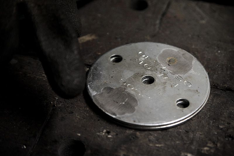 At least it's all done now. The next morning we removed the gearbox to get started on the sump conversion but that ended quickly in a fail (that's a story for another day) so it go left on the temporary table.... 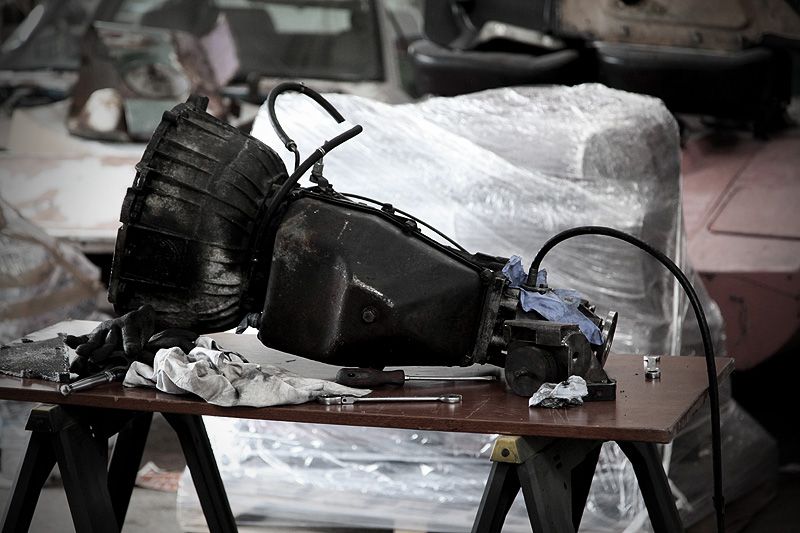 ....while attention turned to the once again big empty void in the middle of the car. 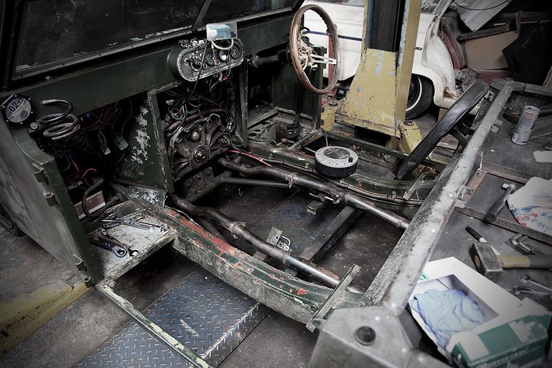 |
| |
|
|
|
|
|
|
|
|
Bruce, good to see you getting some use out of the lathe at last
you might want to keep an eye on homeworkshop.org for people selling tooling.
Cheers
Brian
|
| |
|
|
|
|
|
|
|
|
I've loved this car since I saw a pic of it in a mag (SM?) quite some time ago. This thread has really brought it to life so massive thanks for sharing it. What you all get up to in that lock up is truly inspiring.
I'm hopefully picking up a new car next week and this has made me think that I really need to stop driving around in stock old bangers.
|
| |
Jaguar S-Type 3.0 SE
|
|
ruffgeezer
Posted a lot
   Attracts french tat.
Posts: 1,252
|
|
|
|
Do you have any idea on sizes of the tooling/ live centres that you need? I have a few handy contacts so might be able to "turn something up" Sorry... I'll get me coat  |
| |
|
|
Rob
Part of things
 
Posts: 252
|
|
Jun 10, 2012 11:33:10 GMT
|
|
just read this from the beginning, and the thing is awesome. just be sure to use the correct oil for that box, not dextron 3. they get curse word about it and break. not the best box but hey ho.
|
| |
|
|
|
|
|
Jun 10, 2012 14:58:36 GMT
|
Bruce, good to see you getting some use out of the lathe at last you might want to keep an eye on homeworkshop.org for people selling tooling. Thanks Brian. I'm so pleased to be getting some use out of it now. It sat for a long time until I got the three phase connected, then it sat for even longer due to it being covered up (out of sight, out of mind) but since Dez came down and got some work done on it, I'm really inspired to start using it more.  I'll take a look at that website when I get a chance. I know quite a few tools are needed, but I don't really know where to start (especially with my current lack of budget) I've loved this car since I saw a pic of it in a mag (SM?) quite some time ago. This thread has really brought it to life so massive thanks for sharing it. What you all get up to in that lock up is truly inspiring. I'm hopefully picking up a new car next week and this has made me think that I really need to stop driving around in stock old bangers. Thanks for the kind words. One thing I would say, there is nothing wrong with having a standard old banger....it just seems to be more fun owning a modified one.  Do you have any idea on sizes of the tooling/ live centres that you need? I have a few handy contacts so might be able to "turn something up" Many thanks Tim, I currently don't have a clue what sized of what I need, but I'll look into it and let you know. Anything you think you can get cheap will be a massive help. Many thanks again. ;D not the best box but hey ho. I guess there will always be someone out there suggesting something bigger/better. On my (very limited) budget I was pretty pleased to have picked up this box. I've been told by numerous people that it's a massive, massive improvement over the BW65 plus I get a 4spd instead of a 3spd. On top of that it should be easy to get bits for because they came in a numbe of common cars (bought a new filter, sump gasket and O-rings last week for £12 delivered) I am sure there are better boxes out there, but 'hey-ho' aside, I doubt I'd have been able to afford one even if I wanted to. This one will do me and I am pretty please to have got it. I'm aware of the trans fluid needed, I have the DAF manual for it which outlines all the recommended oils. Thanks anyway.  |
| |
|
|
Dez
Club Retro Rides Member
And I won't sit down. And I won't shut up. And most of all I will not grow up.
Posts: 11,790
Club RR Member Number: 34
|
|
Jun 10, 2012 15:15:47 GMT
|
|
i think the lathe needs 1" tooling bruce, going from memory, cos my 1-1/4" stuff was too high on the centreheight.
|
| |
|
|
ChasR
RR Helper
motivation
Posts: 10,309
Club RR Member Number: 170
|
|
Jun 10, 2012 15:23:30 GMT
|
Are you sure Rob? A number of people reckon DIII is backwards compatible with Dextron IID, including Ashcroft transmissions and the chaps who convert these for other classics  . To be fair it is a simple(ish) box to work with, as long as you don't rev it too much in neutral (something to do with the A clutch pack always being partially engage; there were emissions testing procedures written for these 'boxes ) in addition to ensuring it receives spotlessly clean oil (one reason why mine went up in smoke). The lockup drive in 4th gear is probably the biggest difference I noticed. Going from another BW35 Stag which was screaming at 70mph, it's quite a serene experience in mine in addition to the fuel gauge not moving quite as quick to empty  . Good to see you are getting stuck in there. Not long before it hits the road again then? |
| |
|
|
|
|
|
Jun 10, 2012 15:33:17 GMT
|
With the gearbox back out and me left looking for a new solution to a problem I'd thought I'd overcome, I decided to turn my attentions to tidying up the area around the sides of the transmission tunnel....particularly where I'd cut out the original crossmember. This is one side where I'd cut the original crossmember back to clear the ZF gearbox. The angled piece coming up off it is where the seat frame mounts to this was realistically as far back as it could be cut (I'd have cut the box section further back but it proved impossible to get a grinder any further in whilst still keeping the cut neat). The edges were still jagged and rough...time to clean it all up. 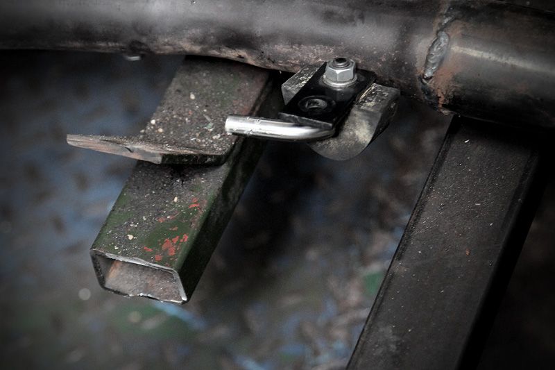 While I was cleaning up the edges with a flap wheel and getting everything nice & square, James cut some sections out of the centre part of the original crossmember that I'd removed early on. 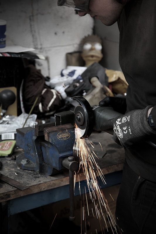 I then put a slice in each corner of one end of the newly cut section and clamped it in a vice to squeeze the ends together slightly 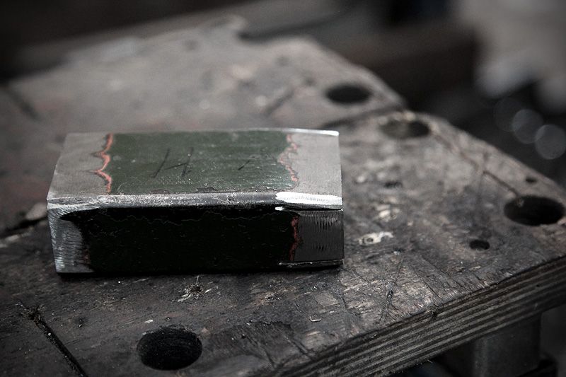 I didn't need much of a slice out, just enough of a pinch so that this end would sit flat/flush against the new crossmember which was 5mm shallower than the original one. 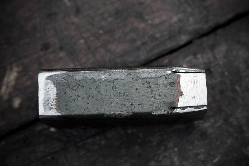 I then welded both sections along the notches/slits and dressed them back. 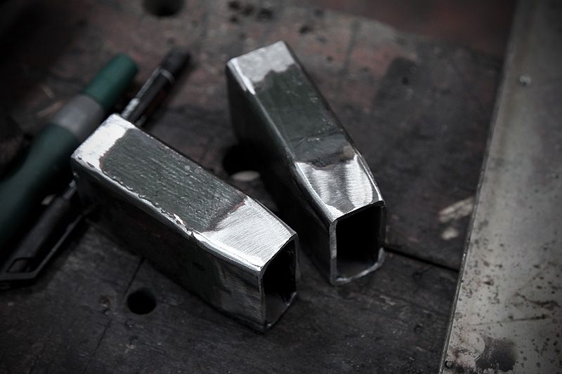 Next up I cut some plate down and welded it onto the ends of the original crossmembers to cap them off. The holes were already in the plate so I left them there but may well fill them with weld when the car is next in the air. Only one edge was dressed back as this stage.... 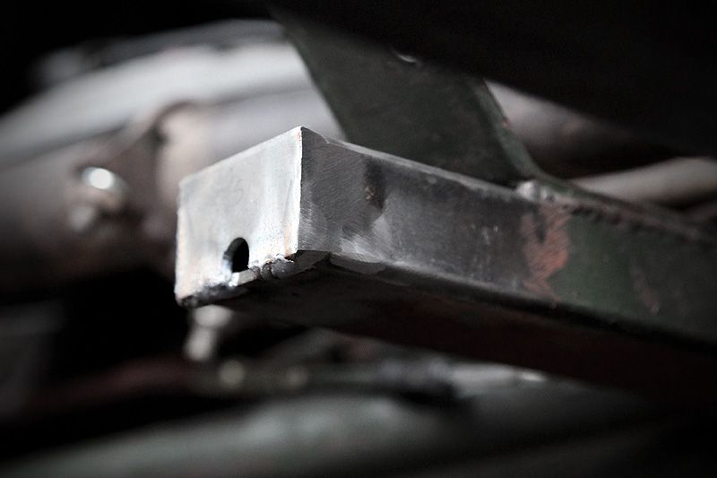 ....because I then welded the sections in to tie the two crosmembers together. 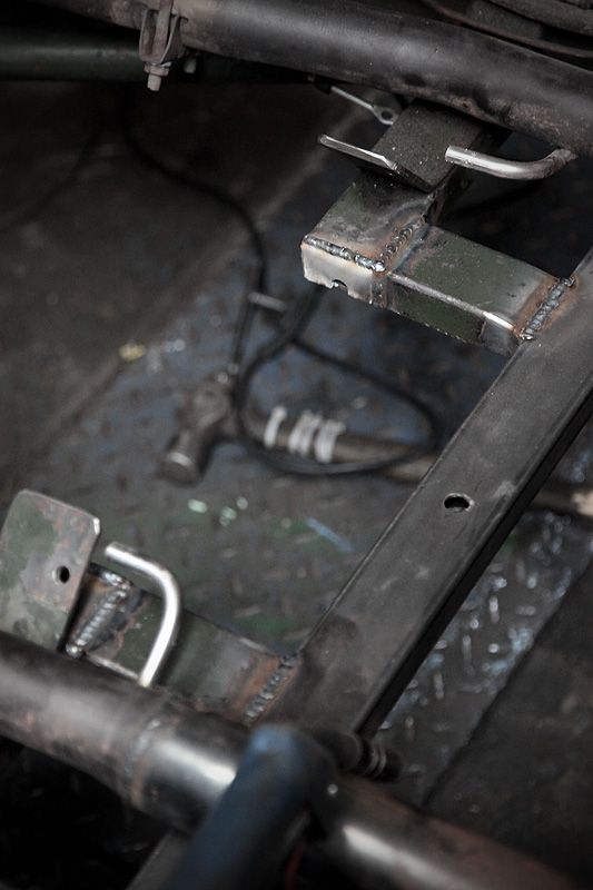 I just thought it made a neater solution than having a stub of open ended box section jutting out into the transmission tunnel. It also added a bit more strength to the new crossmember. 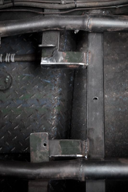 Most of the welds dressed back now, I decided to leave the one where it joins the new crossmember. Hopefully all this lot will look a bit neater once it's all got some paint on it? 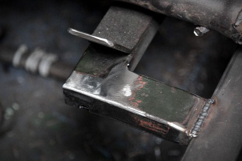 So that was most of the main fab work completed. From what I could tell, that was all the welding done and now it was time to turn to this lot..... 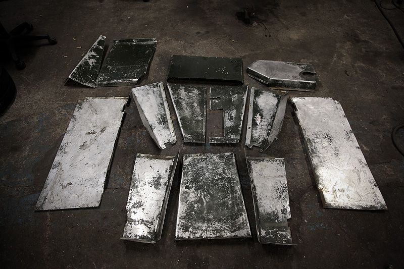 ...the panel work! I'd been looking forward to doing this because I've never done custom panelwork before. This was going to be a new challenge and a whole new learning curve. ;D |
| |
|
|
|
|
|
|
|
Jun 10, 2012 15:40:46 GMT
|
I'd been looking forward to doing this because I've never done custom panelwork before. This was going to be a new challenge and a whole new learning curve. ;D This was my initial enthusiasm for trying out something new. I very quickly learnt what Dez and Ian had previously been telling me, "Panel work is a proper ballache to get right" Theory and practice are sometimes the same, but sometimes very, very different. I quickly found out that this panel work malarky was very much the latter. VERY much! Making panels is one thing, but making them to fit how I want them, to a tolerance I am happy with....that's something else. Oh well, better get stuck in! (update to come soon....) |
| |
|
|
|
|
|
Jun 10, 2012 18:55:09 GMT
|
Fair play Bruce, I'm sure you'll get the hang of the panels in no time - you have an enviable knack for such things  Really enjoying the updates, I know the time spent doing all this stuff isn't reflected in the writing so thank you for keeping out there and therefore keeping me intrigued/entertained sitting here reading about it |
| |
Club Retro Rides Member
|
|
ruffgeezer
Posted a lot
   Attracts french tat.
Posts: 1,252
|
|
Jun 10, 2012 21:13:22 GMT
|
I think the lathe needs 1" tooling bruce, going from memory, cos my 1-1/4" stuff was too high on the centreheight. Is that the required shank size? What would suit it live centre wise? Moreover, what sort of lathe is it? |
| |
|
|
|
|
|
Jun 10, 2012 21:33:37 GMT
|
I think the lathe needs 1" tooling bruce, going from memory, cos my 1-1/4" stuff was too high on the centreheight. Is that the required shank size? What would suit it live centre wise? Moreover, what sort of lathe is it? quite an Early Harrison L5, with MT2 tailstock. toolpost isn't original and i can't remember what size tooling suited it, i had loads of odds and ends, but rarely bought anything new for it. |
| |
|
|
|
|
|
|
|
Thanks for the info about the lathe and tools Dez and Brian. As you can probably gather, I know very little about the lathe itself....but I'll measure the tooling that I've got and also the distance from the toolpost to centre height. With the panel work I had decided to concentrate on the area around the transmission tunnel and floor in between the chassis rails. I eventually want to replace all the interior panel work but the outer floor sections and footwells can wait until another day...most of those panels are unaffected by the changes for the new gearbox so I can live with them for now. This lot certainly need to be re-made though in order to get the car back in one piece. They are placed in order of how they sit on the car with the furthest panel being the one that sits under the centre of the dash, then the front of the transmission tunnel in the middle and the rear of the transmission tunnel nearest. The panels to the sides are the sides of the transmission tunnel/floor pans up the the chassis rails. 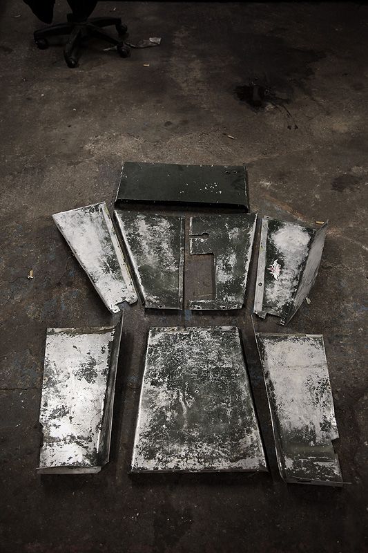 Not only is the tunnel taller than the previous one, it's also now a different shape and on top of that I have to cater for the lower seating position which means the rear floor area has to be completely different. Instead of a one piece panel like the original, with the seat brackets sitting so low it's now impossible to make the in a single panel....instead, three separate panels are needed otherwise you can't fit them or remove them without cutting something. After a good few hours trying things out I managed to find a solution that seemed to work. The tunnel side was fairly simple, followed by the rear angled panel but the floor piece was a real ballache thanks to the rise of the chassis rail. I couldn't follow the rise because the seat sat below this line so the floor panel had to be notched around the chassis rail. I decided to start making it from little bits & offcuts and building it up piece by piece to the right shape.... 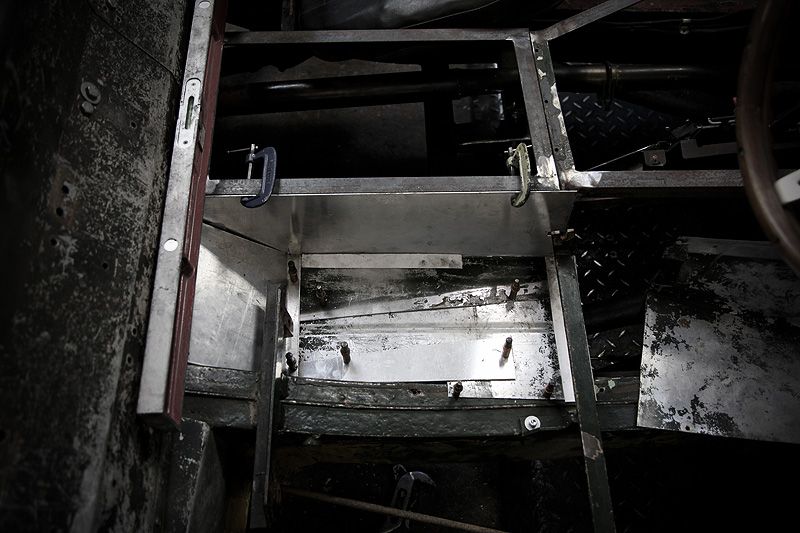 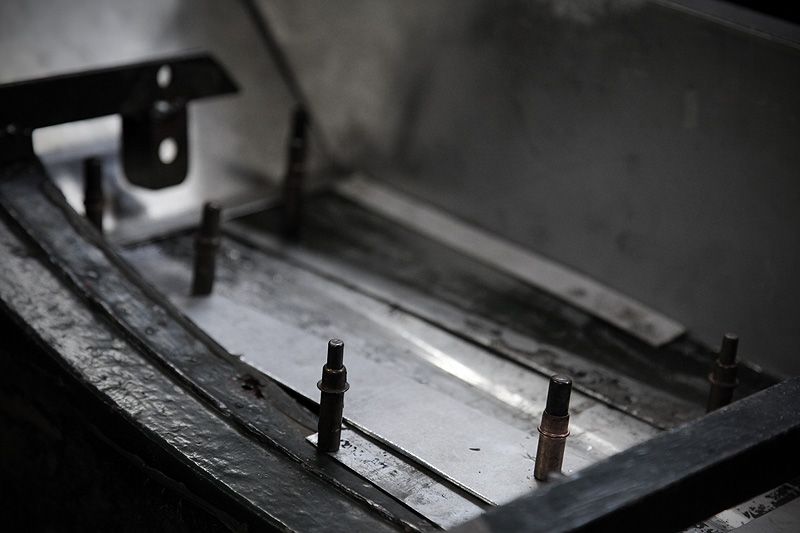 Gaz (Pickmeup) had kindly offered to lend me some Cleco pins and I have to say, they came in flipping handy! Being able to construct a panel out of smaller pieces and hold them together as more bits were added was amazing. On top of this, having a couple fixed through the chassis rail to hold it all in the correct place made things far more accurate. I could remove the whole panel anytime and refit it perfectly every time. I'd never used them before, but have to say they are simply brilliant in helping build the panels up! 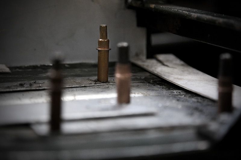 The three rear panels in place. It looks so simple and easy looking at it now, but this area alone probably took me about 6 hours of templating, cutting, folding and trimming. They are only loosely placed in for now but any gaps will close right up once they are properly fitted. 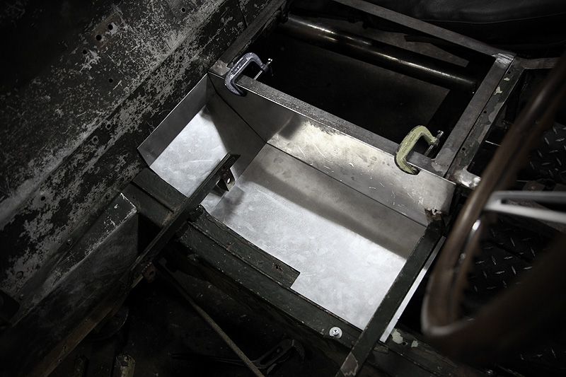 One of my aims was to make things as accurate as possible. I decided to use the seam along the top of the chassis rail as an edge to but up against. Not being straight or true meant lots and LOTS of fine trimming to get the panel to sit nicely without awkward gaps. Where it notches is where the chassis rail starts to rise and here I simply ran the panel along the side of the chassis, again, as closely as I could 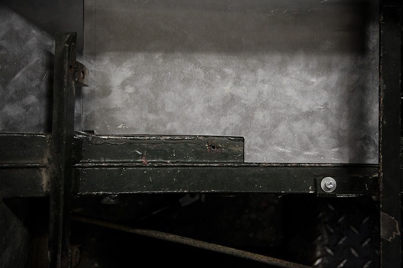 Here you can see more clearly where I had to notch the floor panel around the chassis rail. It also shows the drop bracket for the seat which shows how much lower the floor in this area needed to be in order to clear the new seating position. 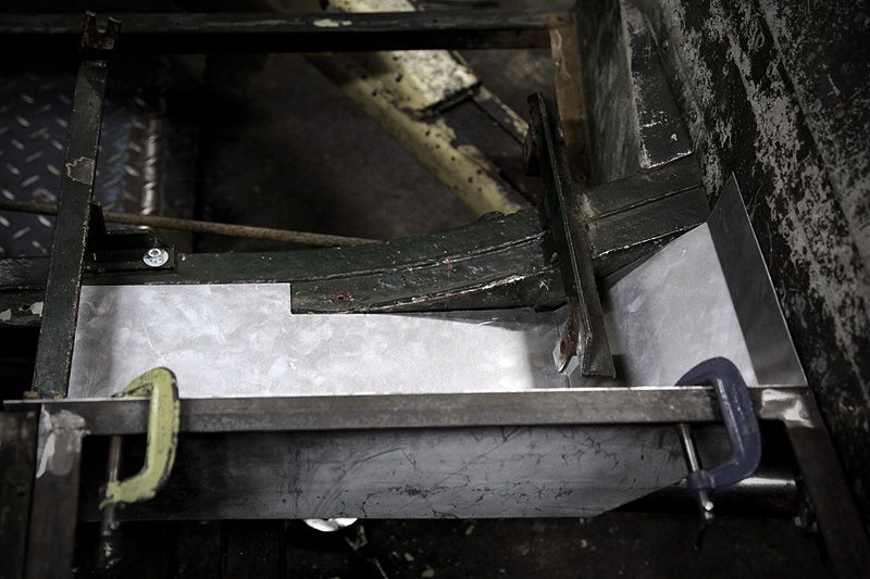 My lovely template - constructed from bits of ally and card (which were used to close the last few millimetres of gap around the edges). Once the template was complete I taped all the parts together then removed the Cleco pins - leaving them in meant I couldn't use the template to draw around onto fresh ally sheet. Once drawn around onto the final piece, the line equates to about 1mm extra on each side which works out quite well because it gives me chance to file the edges down bit by bit for a perfect fit. Apologies for the very fuzzy pic, it was late and I was tired. Shakey hands were mandatory by this point! 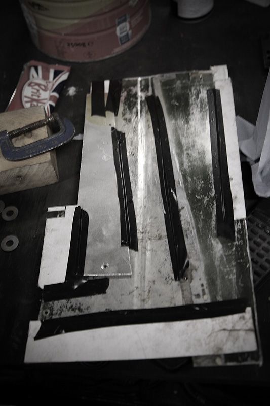 So that was one seventh of the panels needed. Only six more to do! By my initial calculations this would equate to somewhere about 40+ hours just for the panel work if they all went as smoothly as this. Then there will be the bead rolling and the fitting. All of which sounds simple, but as I was finding out, nothing is as simple as you think when it comes to this kind of work! |
| |
|
|
|
|
|
|
|
With the offside rear section done I decided to do the same on the nearside. I'd learnt early on that this car was not symmetrical. With that in mind I decided not to try and use the offside panels to replicate the nearside ones....instead I figured it best to crack on and make them from scratch. Again, some offcuts of ally, lots of Cleco pins and a good few hours later I had the other side done. 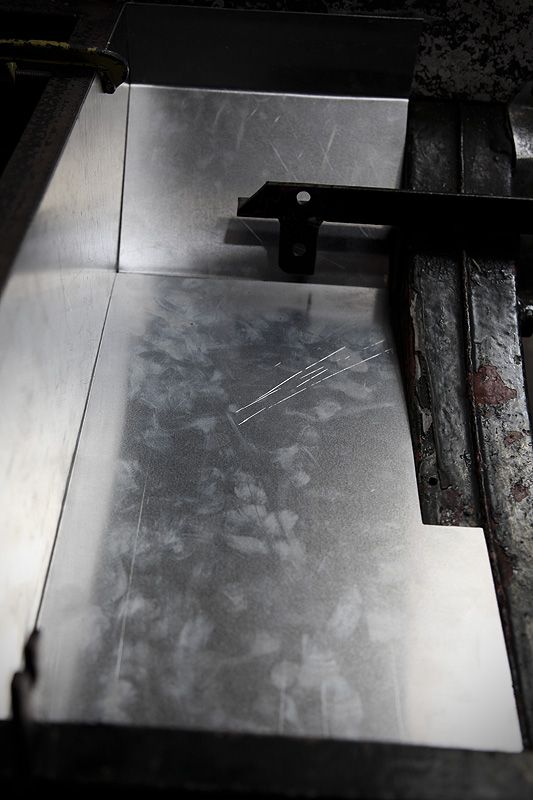 Back in December Ed (RadDat) had kindly donated his little metal folder to Area 52 after having secured a bigger one. This was a real godsend in making the folds in panels. Nice crisp folds were acheivable with little effort. 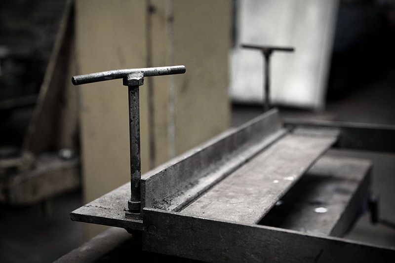 My other tools were a slitting disc, flap wheelanother, longer folder that Si (B8D) had helped to make a year or so ago. I don't have a nibbler and find tin snips distorts the metal more than I like, so a slitting disc is my main method of cutting panels to the correct size. It burrs the edge quite a bit, but with care, nice straight edges can be cut easily with the flap wheel used to de-burr everything. A file is also handy for crisping the edges up or getting into tight corners. The flap wheel is also useful for buzzing off tiny amounts to get panels to fit perfectly, this is particularly handy for getting the edges so sit nice and snug along the chassis seams which aren't straight or even (they look it to the eye, but offer a straight edge along it and you soon notice uneven gaps). Whilst the longer metal folder is great for sheet steel, the design of it doesn't allow for perfect 90 degree folds in ally where the metal tries to spring back more than steel. Initially I hammered the edges to a right angle but found it left some marks in the ally. I've since started using a piece of box to hammer the edges nice and crisp which works a treat and doesn't leave any hammer marks. One of the panels in the nearside section will be remade later on because I'm not happy with the finish of it thanks to my early attempts and getting a nice right angle. 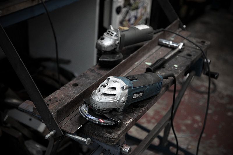 The notch on this side worked just as well as on the other side sitting nice and snug against the chassis rail 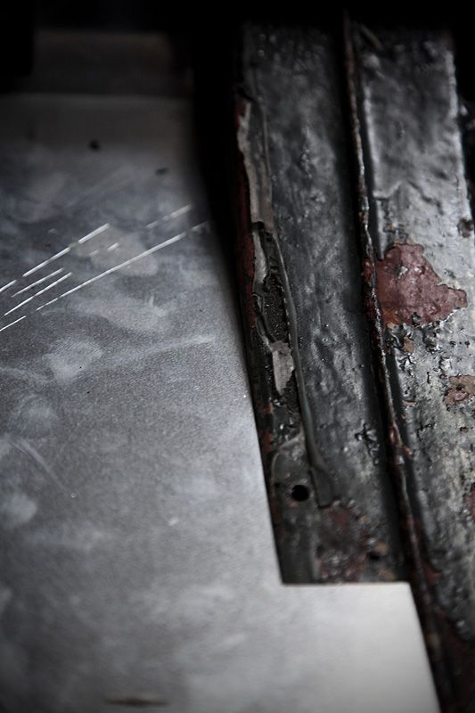 The edge along the chassis seam is also as accurate as I'd want it to be. Overall, despite taking a lot more time than I'd have thought, the panels were fitting as nicely as I'd planned in my mind. 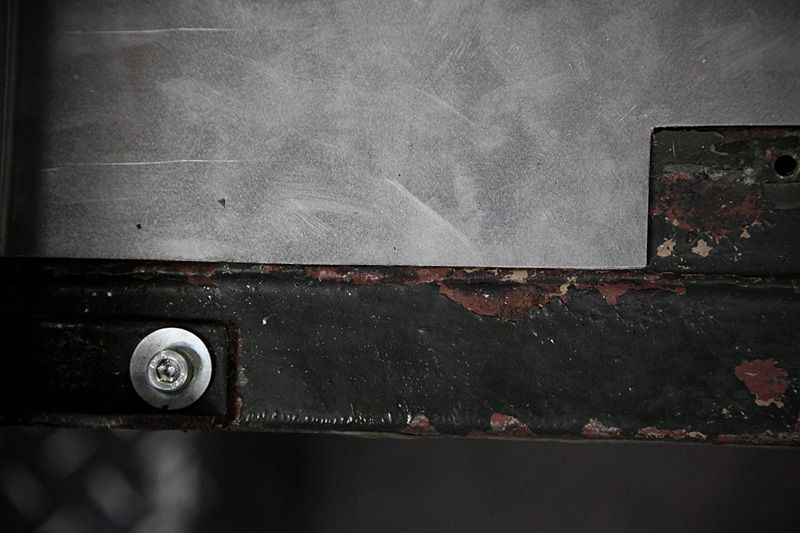 Apart from wanting to redo one panel (out of six so far) things were as I'd have hoped regarding fitment and accuracy. The panel I'll remake won't take too long because I now have a nice accurate template to work from. The learning curve continues.....time to start the next panel. |
| |
|
|
|
|
|
Jun 11, 2012 10:38:54 GMT
|
|
|
| |
|
|
|
|
|
Jun 11, 2012 11:10:18 GMT
|
I absolutely adore Randy's Jeep - ever since I first saw it I loved it. I also love how two similar concepts can go two totally different routes. The Jeep being all American and following a very military theme, the Land Rover being all British (pedantries of the engine origins aside) and following a very organic theme....a kind of 'lost & found' approach to its aesthetics. I don't want to fall into cliche by calling it rat or patina'd  I love both equally for the way they set out to, and acheive, their goals in becoming a vehicle that is very, very far from its stock form but still with the core look and essense of the original that makes them unmistakably recongnisable as to what they are. Or were. Long live the both of them ;D |
| |
|
|
|
|
|
Jun 11, 2012 11:42:08 GMT
|
With the rear sections of the tunnel sides/floor done (albeit with one panel to remake a bit better) I got started on the front section of the tunnel sides. Kicking off with the nearside. Lots of bits of plate held together with Cleco pins, some folding, lots of fiddling and trimming and it was pretty much there.... 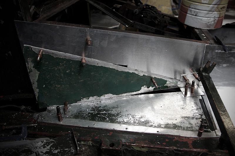 Where it meets the rear section I had to do some gentle folding to get it to sit against the change of angle.....and chop it around where the seat frame comes out. I have deliberately given enough overlap that I mount the panel either in front of, or behind the rear section. Not only do I want all the panels to fit perfectly, but I need to make sure that I fit them in an order that makes removal easy. 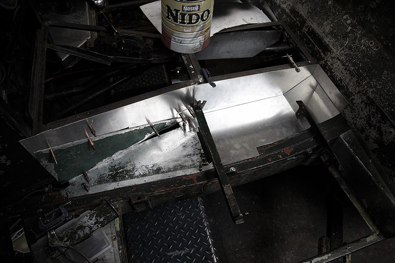 The original set-up meant taking nearly all the internal panels out just to be able to get the sides of the transmission tunnel off. Seeing as the most likely reason to remove any panels is to work on the back of the engine or the gearbox, it seems pointless to make all these from scratch only to have a similar arrangement when it's all fitted. I'm trying to design all the panels to look aesthetically 'right' but building them also in an order where getting to the inside of the tunnel doesn't mean undoing/removing everything. Simple in theory, but getting it to work without awkward joints was more challenging. None of this will mean much at the moment, but the more panels I make, the more important it'll be to get them sitting nicely with good, logical join lines whilst having them removable in a much more logical order. Basically I'm having to plan all the panels and their folds/joins/sequence of removal right from the outset. 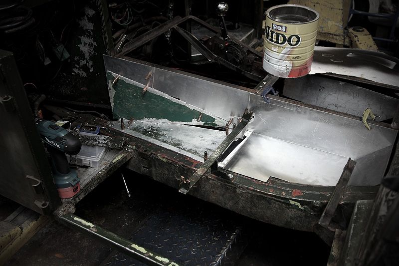 Front side/floor panel made. Looks so easy when I see it like this because it just looks big, flat and with only one fold. It wasn't! 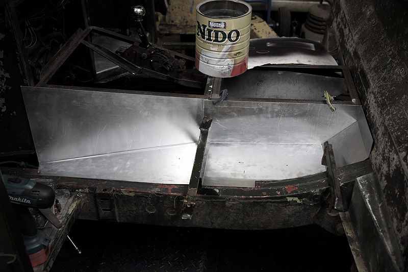 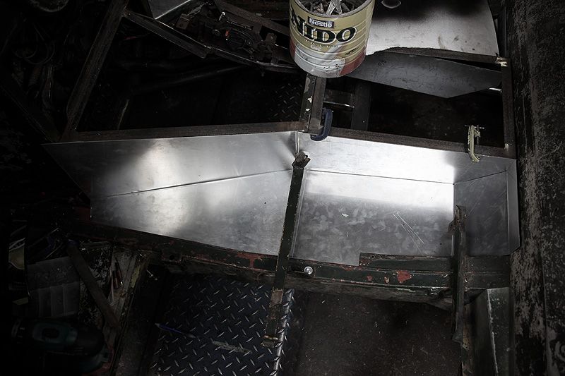 Starting to look more like a transmission tunnel now... 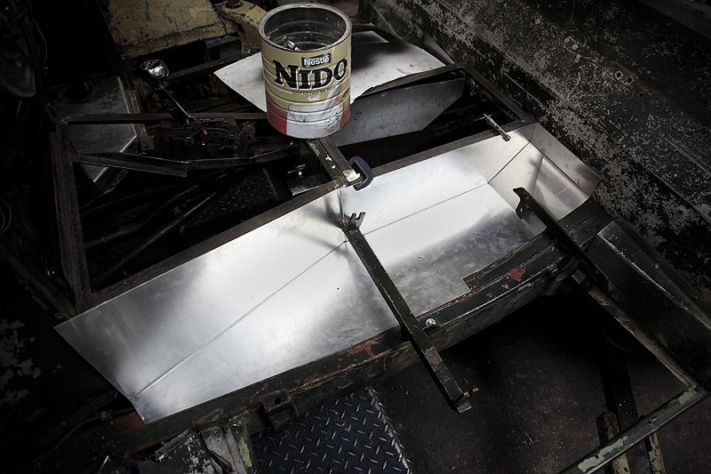 Lines up perfectly along the chassis seam...and with the rear section floor panel 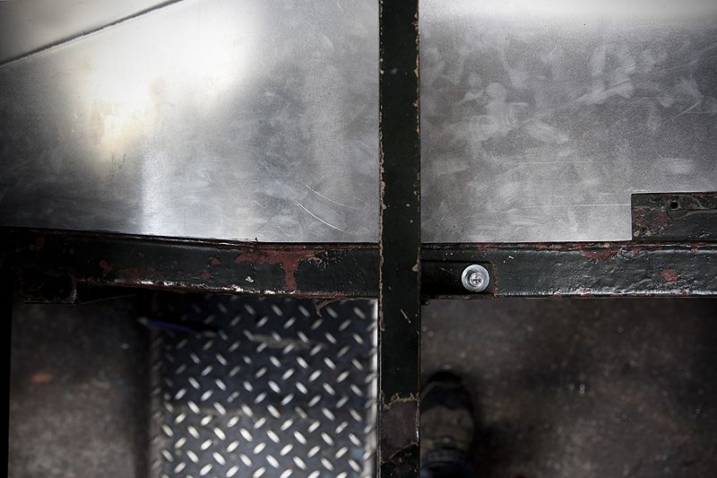 The tolerance along the (not straight) seam is pretty pleasing. There is a also a kink in the seam/chassis just out of view (bottom of pic) where the chasiss rails start to close in towards each other. As I said, this isn't just a straight edge... 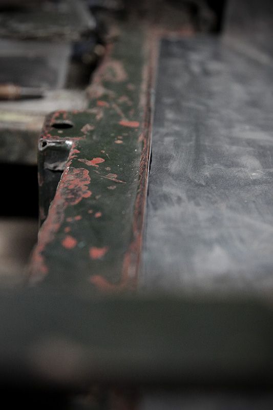 Next up....a deviation from my original plans which leads to a 15 hour day making one single panel. One which I wasn't intending to tackle yet....which in turn leads to a rethink about how I want to make/fit the layout of most of the remianing panels! I do like to make work for myself. |
| |
|
|
Rich
Club Retro Rides Member
Posts: 6,338  Club RR Member Number: 160
|
|
Jun 11, 2012 12:25:33 GMT
|
awesome, coming on nicely now Bruce! Looks so tidy, good job!  |
| |
|
|
|
|


 [*]
[*] [*]
[*]



 .
.


