The secret project is an AA battery powered EL84 amp. The EL84 is the little brother of the EL34 and puts out about 3-5W in class A or 10-15W as a push-pull pair in class AB. I'm planning to use a single EL84 in class A driven by an EF86 valve as in the old Mullard amps, but powering the lot by 4 AA batteries. I'll be using a 555 timer chip to make a 50hz astable circuit, run that through a pair of NPN and PNP power transistors which will be able to deal out some current. This gives me a strong 6V AC source. That goes backwards through a 4.5V mains transformer which should give me around 300V AC. I'll bridge rectify that with 4 diodes and I should have a nice smooth 300V DC to power the amp from my rechargeable AA batteries 
I've bought some goodies, namely a hammerite-finish box from Maplin, some valves, an RS output transformer and a small 4.5V mains transformer.
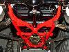
Box:

The planned layout is to have two valves at the front and the output transformer at the back:

I've tested the power supply circuit already. I used the same setup to make the high voltage 100hz spark to light my pulsejets and I can tell you it's quite effective because I've taken a few shocks from it! This is my original prototype from a few years ago that I'm using for sizing up. This is basically what's got to go inside the box:

Plus the battery box, plus the amplifier circuit and it's looking like a bit of a squeeze! I think it'll just about fit:

Original valve amps were built on tag boards and I have no way of making circuit boards any more because I sold my etching tank on eBay to free up a bit of space. I'm going to make this amp on Veroboard because it's much like tag boards but a bit more versatile and I should be able to make the circuits a bit more compact. Inside the box I need two boards: one for the PSU and one for the amp:

For now, that's as far as I've got. I need to get the PSU done first, which is almost identical to the circuit board a few pictures above, except I'll be using smaller transistors. I'm *hoping* I'll be able to squeeze it on because it's VERY tight for space. I also have to allow for some space to pass leads through to a switch on the front panel and a volume control pot.

I've bought some goodies, namely a hammerite-finish box from Maplin, some valves, an RS output transformer and a small 4.5V mains transformer.
Box:
The planned layout is to have two valves at the front and the output transformer at the back:
I've tested the power supply circuit already. I used the same setup to make the high voltage 100hz spark to light my pulsejets and I can tell you it's quite effective because I've taken a few shocks from it! This is my original prototype from a few years ago that I'm using for sizing up. This is basically what's got to go inside the box:
Plus the battery box, plus the amplifier circuit and it's looking like a bit of a squeeze! I think it'll just about fit:
Original valve amps were built on tag boards and I have no way of making circuit boards any more because I sold my etching tank on eBay to free up a bit of space. I'm going to make this amp on Veroboard because it's much like tag boards but a bit more versatile and I should be able to make the circuits a bit more compact. Inside the box I need two boards: one for the PSU and one for the amp:
For now, that's as far as I've got. I need to get the PSU done first, which is almost identical to the circuit board a few pictures above, except I'll be using smaller transistors. I'm *hoping* I'll be able to squeeze it on because it's VERY tight for space. I also have to allow for some space to pass leads through to a switch on the front panel and a volume control pot.