Enbloc
Part of things

Posts: 367
|
|
|
|
Addressing the engine breather system I total rethink was needed. Flatheads, like all engines from from the 30’s era, had pretty much non-existent crankcase ventilation systems. The best you got was a hole to atmosphere. The aftermarket comes through in modern times with retrofit PCV setups, which I’ve run on my previous NA builds. How good they work, I’m not so sure? The PCV setups still vent to atmosphere which is an issue when competing in motorsport. This issue I tried address previously with my sealed system. As documented at the beginning of all this all I managed to achieve was to strangle the whole system which blew the inlet gasket out! Anywho… This has all gone out the window now there is a turbo strapped to the motor. First idea was to go back to a stock baffle, breather/fuel pump stand and vented cap.  The opening of the stand was looking a little worse for wear. 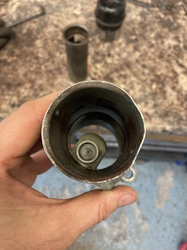 So that got a little tappey tappey tap tap. 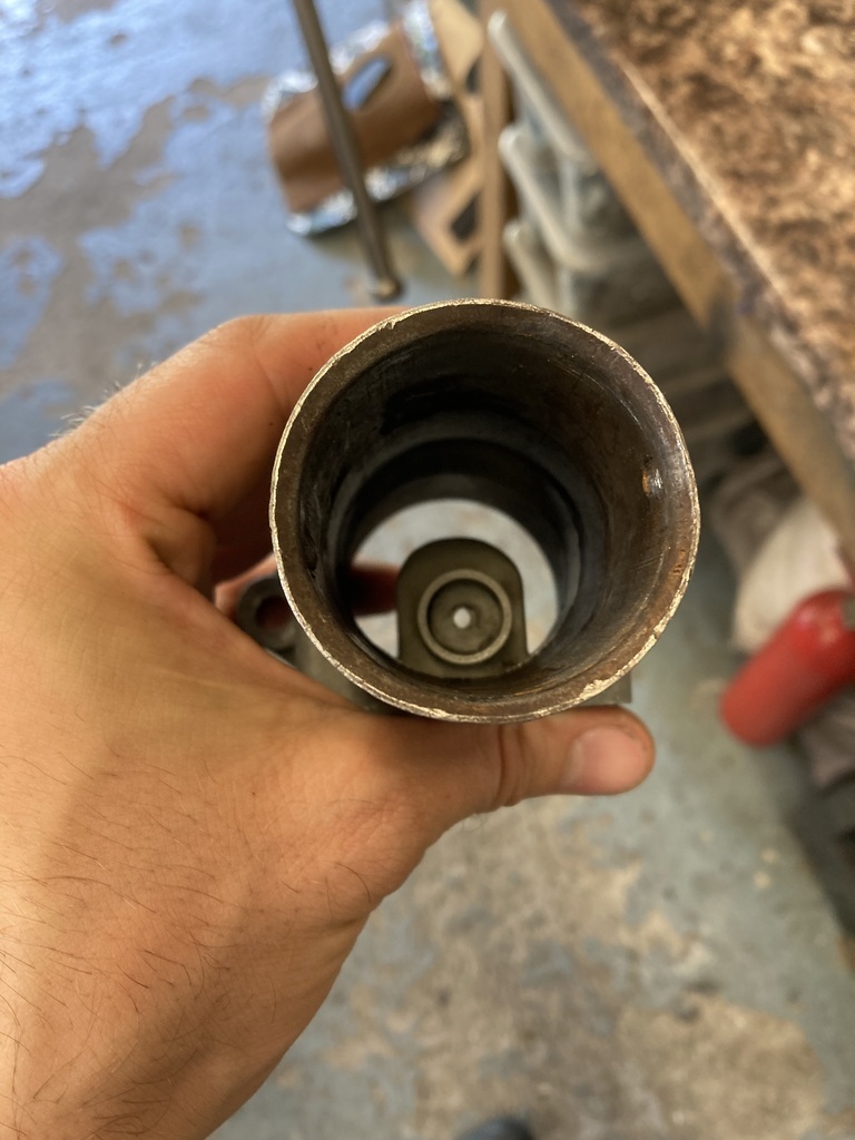 The baffle tube was given a good clean and dropped in the hole.  The stand then got bolted down over the baffle with a fresh gasket. 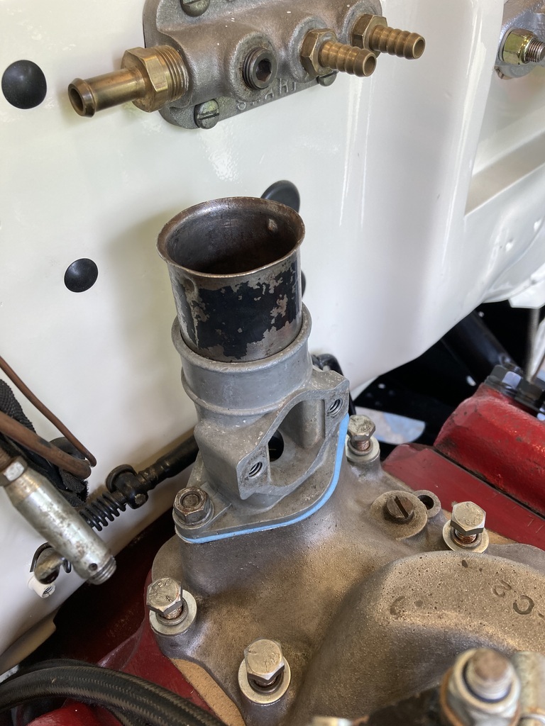 I needed a breather catch can, picking up an OBP one. Finding a mounting spot proved troublesome. An area of firewall was earmarked which meant removing the old fuel block which I’d only really kept for old times sake.  I tried the catch can and it was a fail all round. The barbs were in the wrong locations, too small and more than I wanted. I didn’t want the sight tube either. So that went back. 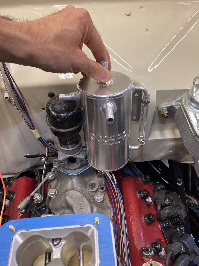 I found a cheap Cheap one on EBay that had just two -10 fittings on the front which was what I wanted. 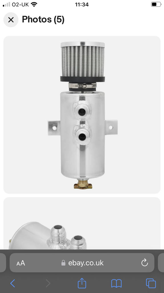 When it arrived it looked like this…! You can’t make this stuff up. 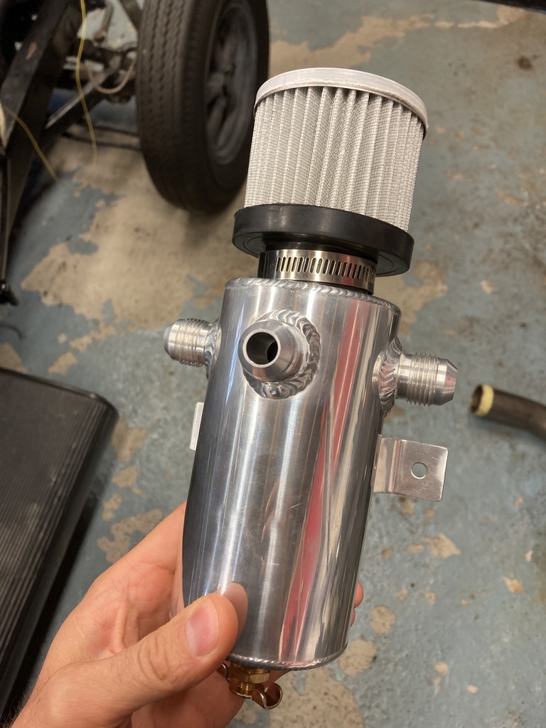 I still couldn’t get my head around using the factory upstand or an effective means of creating a sealed cap so I dug out the old sealed one that I’d made before that was too restrictive.  Problem was, I was now using the drop-in baffle tube so the replacement upstand sat proud on the baffle lip. 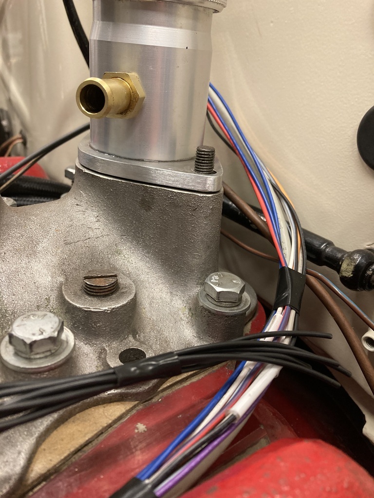 The factory pair work together because of recess cast into the upstand. 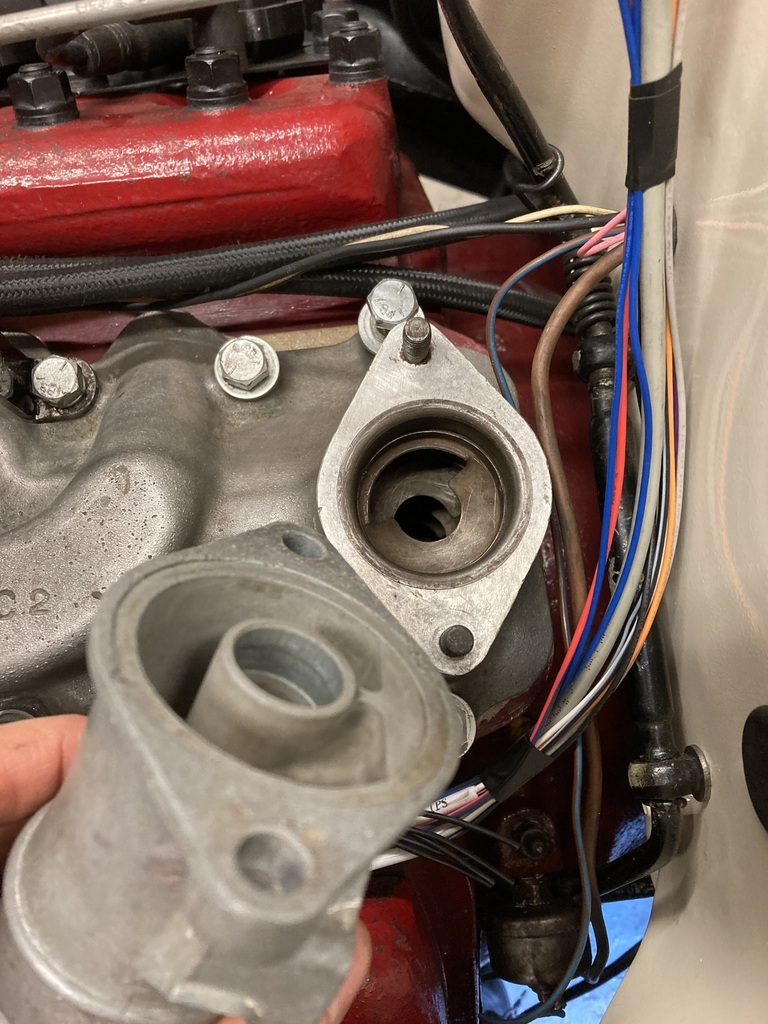 To get around this I used some of that thick gasket paper again which fitted perfect. 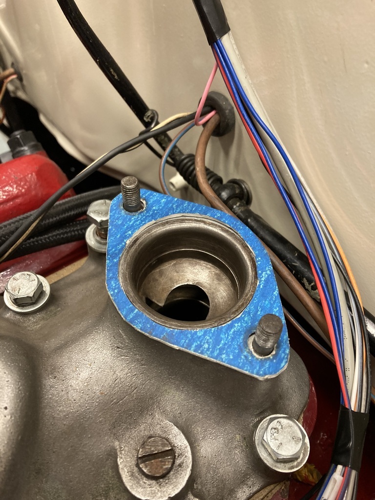 I then got thatshgr high random -10 weld-on fitting that came with the turbo kit welded on as a replacement to the undersized barb’d fitting. 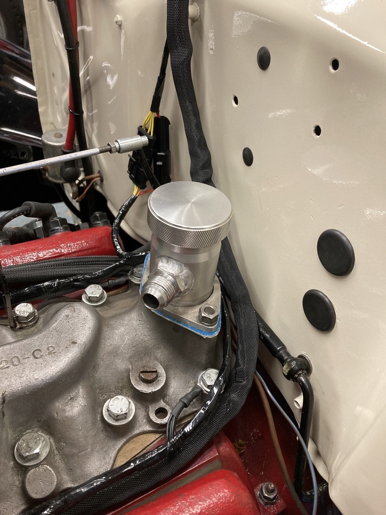 From what I’ve been told a turbo’d motor will push out a fair amount of oil via the breather. This would mean any catch can would have to drained via the tap on the bottom periodically. This sounded like a faff so I always had the idea of running a drain from the catch can back into the sump. Luckily, I’d added that extra 1/2 NPT bung to the sump. This is why I was trying to mount the catch can high on the firewall even though it was ugly and messy. 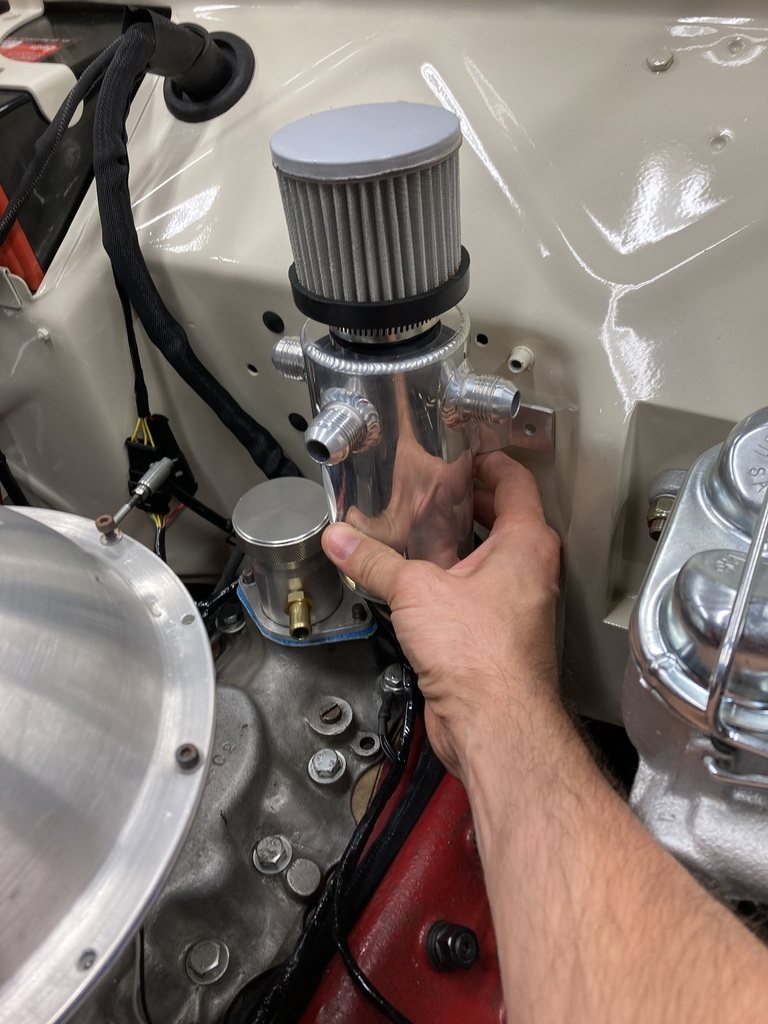 I found I could squeeze the new catch can into an area under the master cylinders. Which was a win all round.  A couple of aluminium spacers were made to move it directly off the firewall for clearance of the brake pipes. 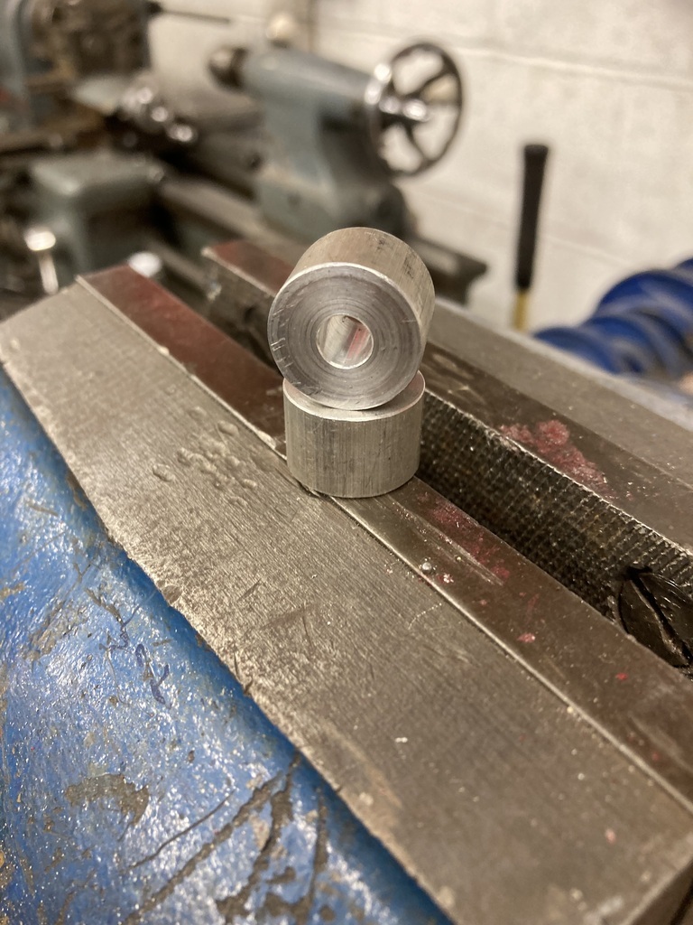 Then went down and dirty with *cough* metric rivnuts. I managed to find two countersunk M6 rivnuts so the spacers would sit flat on the firewall.  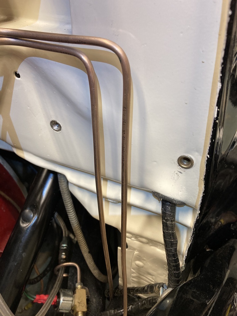 All fitted up.  |
| |
|
|
|
|
Enbloc
Part of things
Posts: 367
|
|
|
|
Doing the initial exhaust down pipe was only really the start. I needed to connect up the wastegate which now sits under the down pipe. 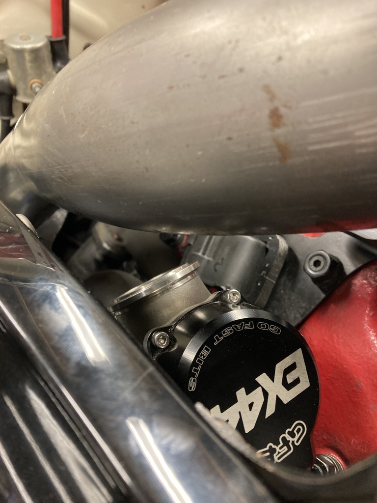 When I fitted the wastegate to the feed side it used 2” exhaust tube. Digging out that same tube to make the exit side it didn’t fit the v-band, being too big. I had a quick scan of the instructions and yep, 2” in, 1 3/4” out. Annoying as I had to pick up a length of 1 3/4” just for that short stub. It was a tricky piece to get an idea of what was needed as I was pretty much working blind. After a couple of rough measurements as a starting point I gradually crept up on the fit after many, many mock ups. 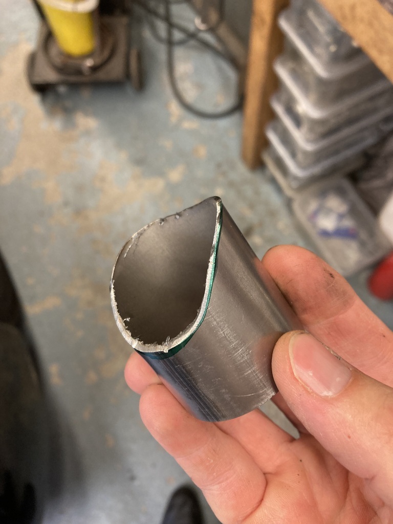 When I was happy with the fit and final mock up I marked its position.  I could then open up the pipe. 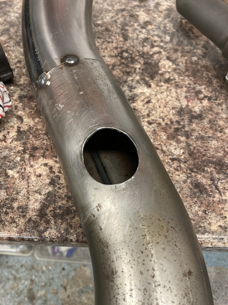 Mocked up again everything got tacked in position. 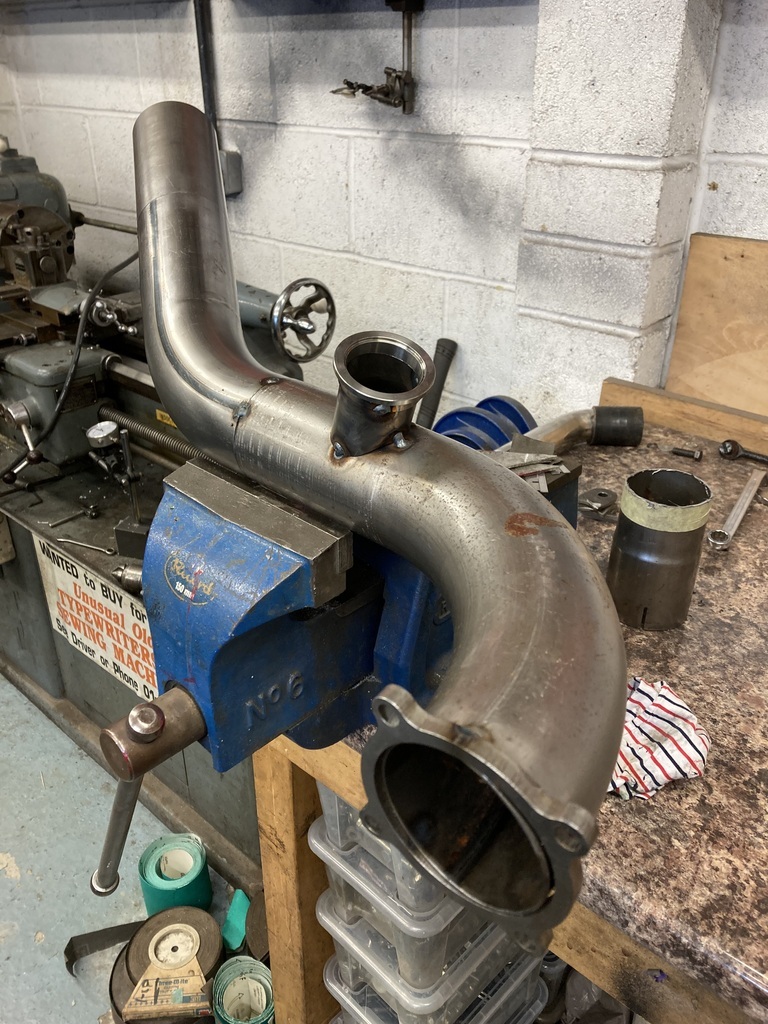 And the final blending of the transition. 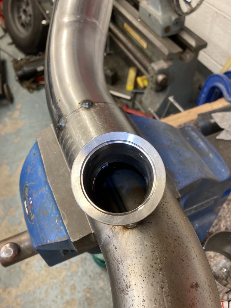 Since the front clip had gone on and finalised how much space I had to work with it became very apparent that an air to air intercooler and associated plumbing setup was out of the question. I think an air to water charge cooler is going to be the future route but that is more than I want to be getting involved with at the moment. A theme that’s going to appear more as I race to get everything finished! What has this got to do with the exhaust? Well, not having a means to cool the intake charge means I’ve had to rein in the the potential boost levels. The wastegate came with 2 springs, a 5 lbs and a 10lbs. Using them individually or in combination gives 5, 10, or 15psi boost ratings on the wastegate. My hope was to start with the 10lbs spring and maybe step up to the full 15psi if everything went well. Running just the 5psi is a bit pointless and the 10psi may be too much. GFB have available a 7lbs spring so I went with this for the moment as a happy compromise. While I was messing with the wastegate it was a good time to swap springs. 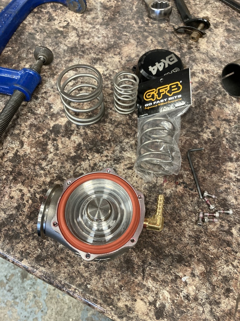 Another add on to the exhaust down pipe was the boss for the lambda sensor. I had the Haltech wide-band lambda add on kit. 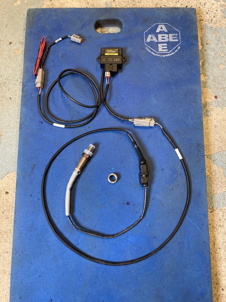 I kinda shot myself in the foot with this as I needed to mount the control box which I should have incorporated it into the ECU mount when I did that. Luckily, I could still squeeze it in with the cables being plenty long enough. 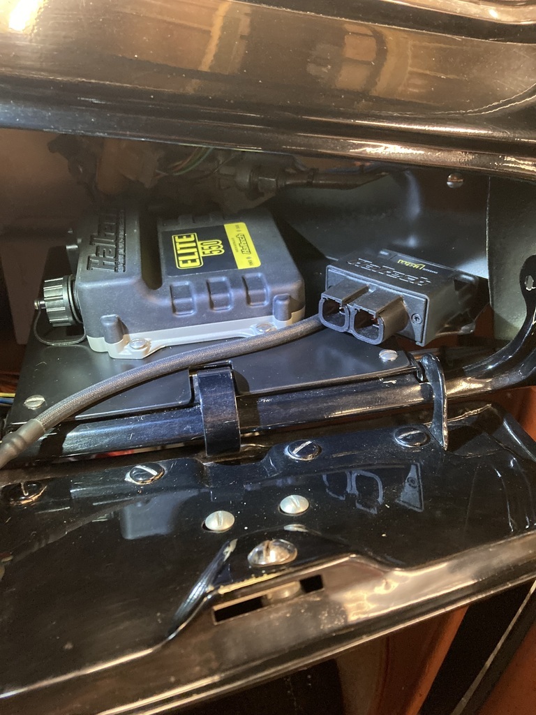 The tray and glove box door were all unbolted again (joy) and the same mounting procedure of drilling and tapping for 10/32 “ UNF screws. 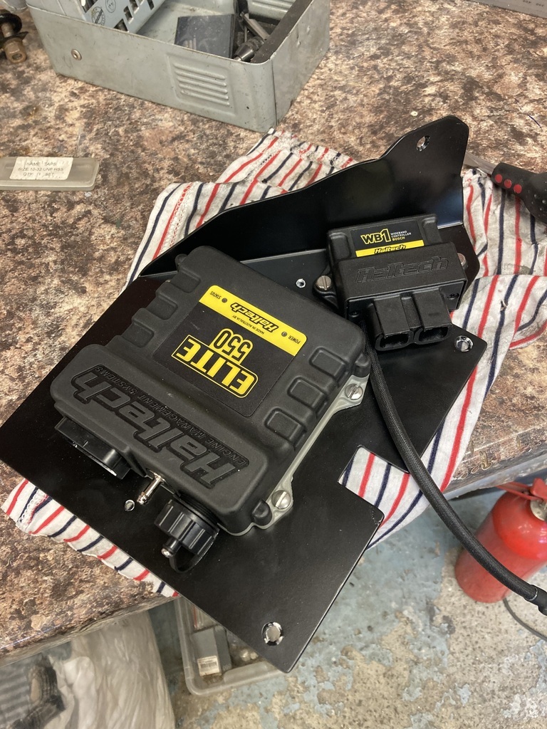 There was some deliberation over the actual lambda placement. I wanted it tucked away on the underside but it meant the lambda would be running downhill which is a no, no as condensation can collect and run back into the sensor. It was relocated to the topside and actually got moved again last minute from the when the picture was taken. 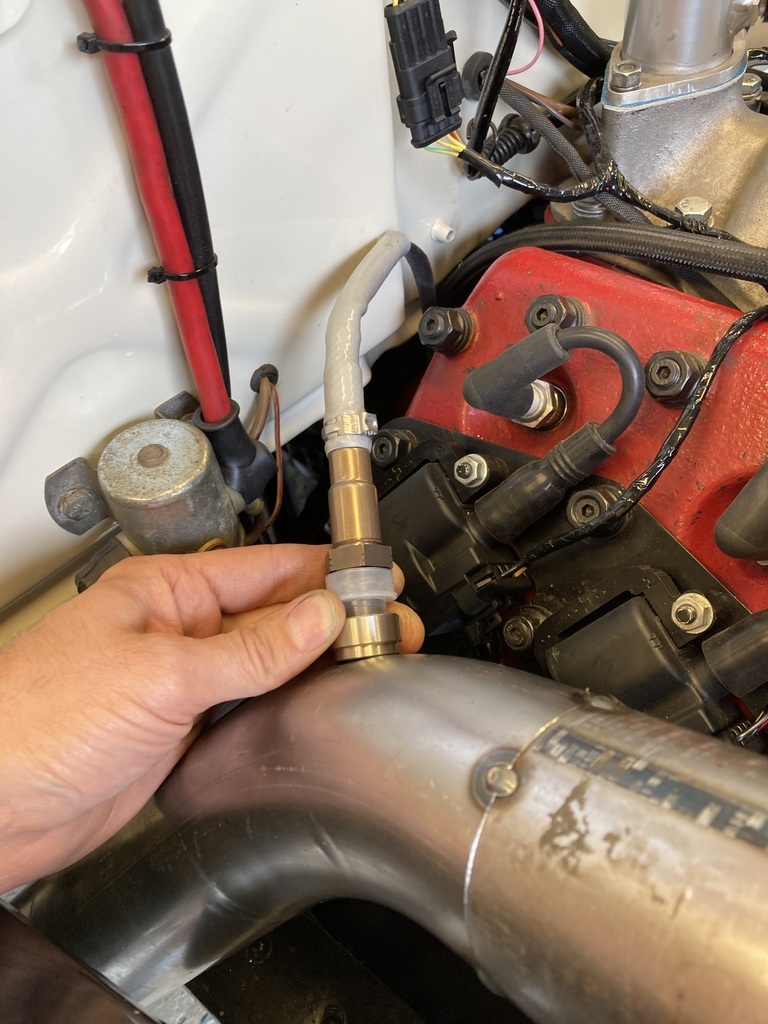 That completed the down pipe so it got removed again for final welding. 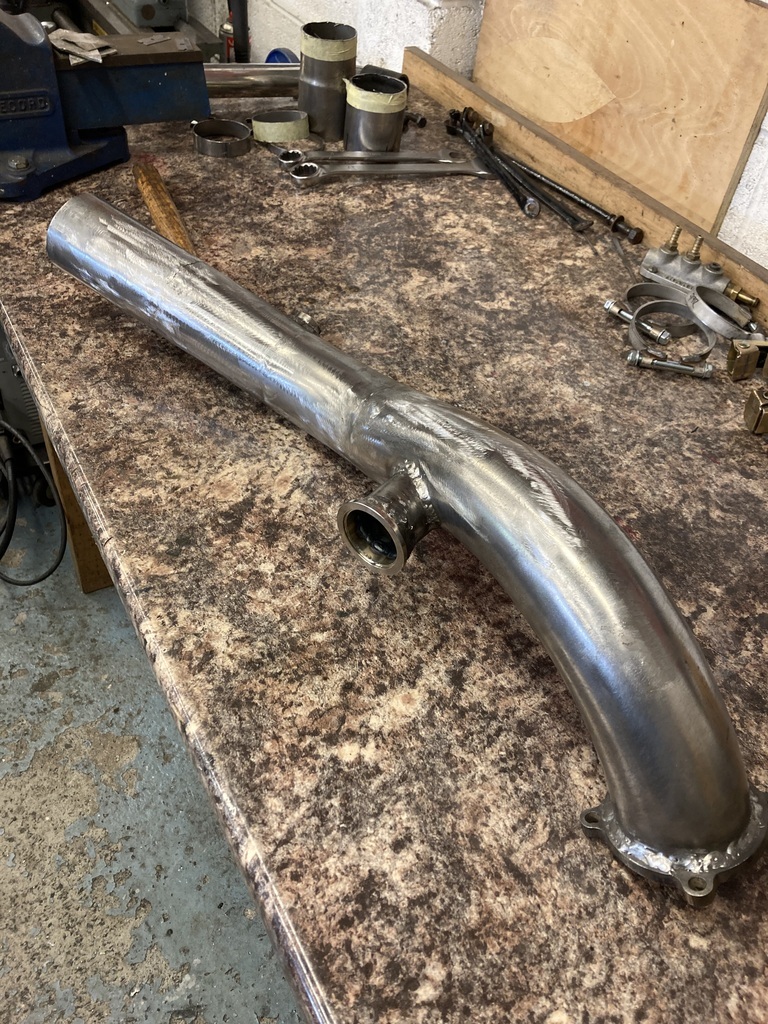 And painted in high temp.  Fitted back on. Everything still fitted. 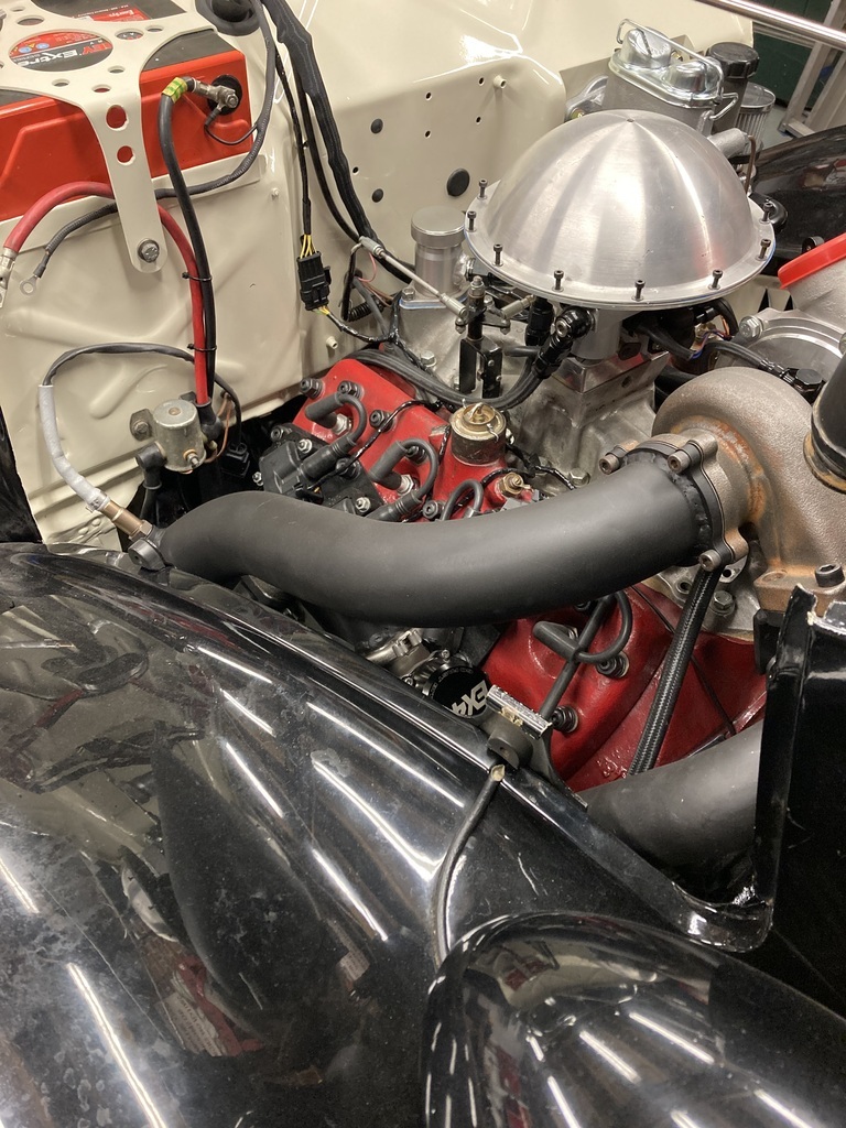 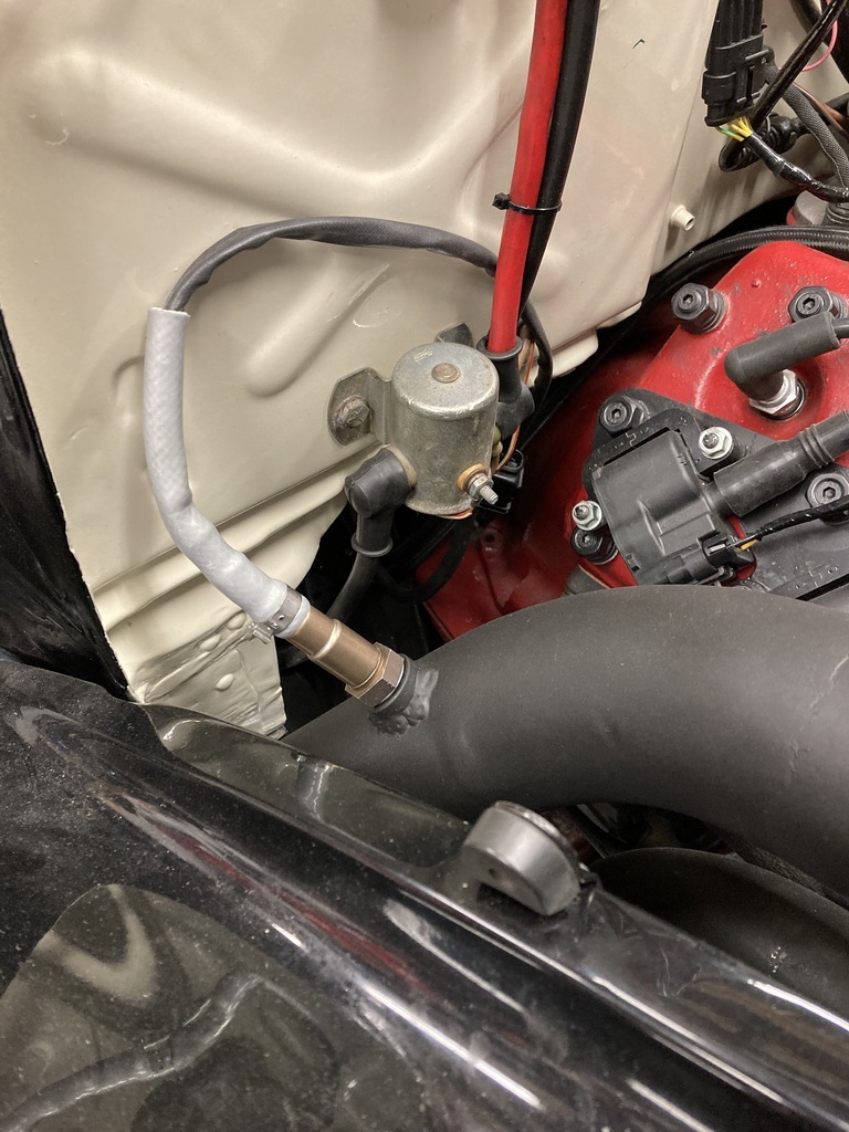 I needed an exhaust mount to support the weight of the silencer. Handily the end of the silencer lined up where the flanges of the front wing and running board meet. Using the hardware already there a CAD template was made to support a rubber cotton reel. 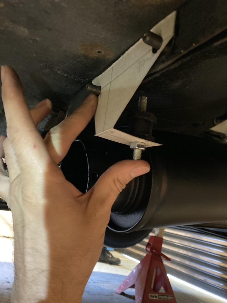 This was copied to 2mm steel with an added support brace. 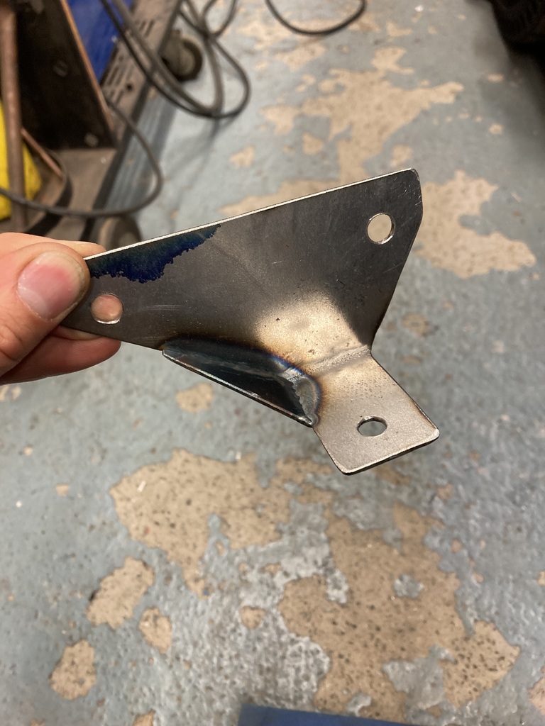 A braced arm was made and welded directly to the silencer. 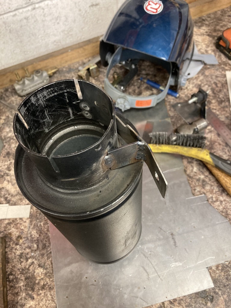 This short length of exhaust and silencer is another rush job. I think eventually it be run all the way to rear of the car as side exit exhausts generally suck and their novelty wears off quite quickly.   |
| |
|
|
Enbloc
Part of things
Posts: 367
|
|
|
|
Remember last year when I stripped the car the complete front clip got dumped on the patio for storage? Well.. Winter turned into spring and spring into summer and it was now in the way being moved around a few times until it ended up the lawn.  I wasn’t too fussed as I knew the time was imminent for its re-coupling. The hold up was finishing the wiring in the engine bay as it was a lot more comfortable sitting on the front tyre terminating wires than bent over the front wings. The re-coupling happened rather quickly as it’s a 2 person job and when help comes it’s all go. The only real prep was to grind the tacks off them disastrous shock mount extensions I made and still hadn’t removed and mount the radiator as the front panels partially hang from the rad itself.  This was the first time the car had been complete with the new motor set-up and it always comes as a shock how tight everything becomes after working around an open engine bay. 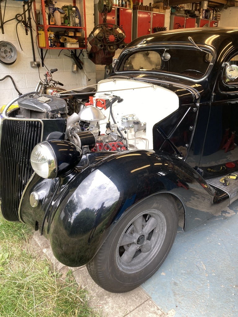 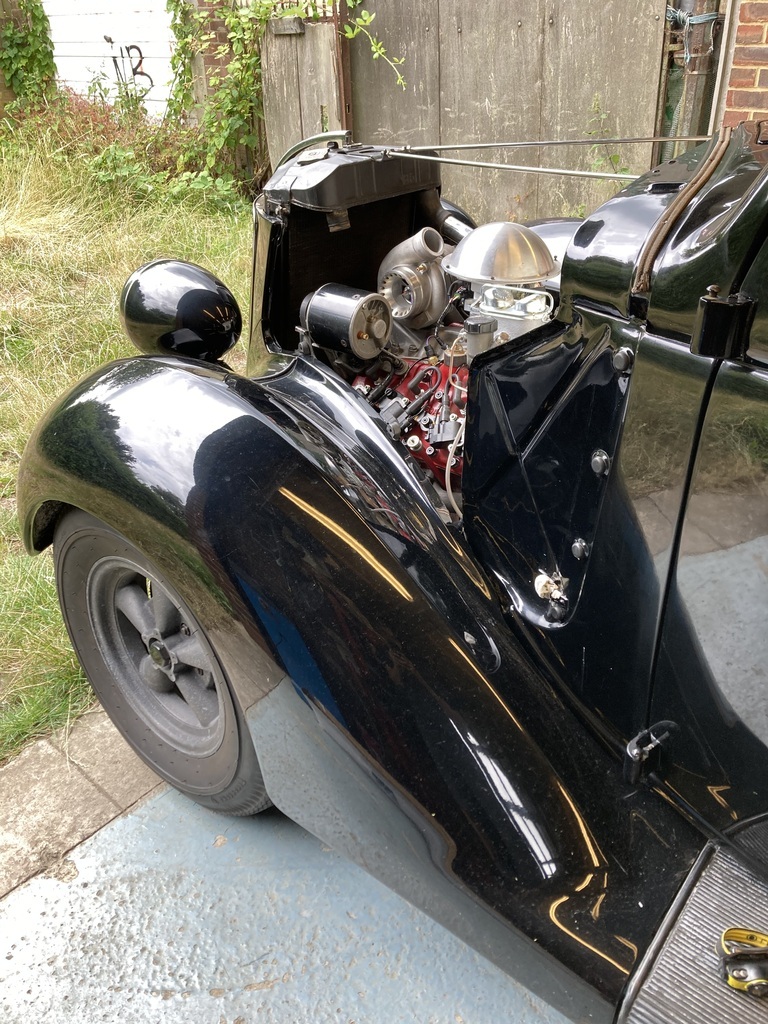 With the front clip on I could finally get on with the final section of exhaust from the turbo. It was always my intention to send the exhaust under the firewall and under the car like a conventional system but the mass of stuff that had accumulated in that corner and the 3” exhaust pipe meant that idea was now a no go. Plan B was to now send it out via the inner wing panel. When the front clip was bolted on it was done without the inner panel on that side. 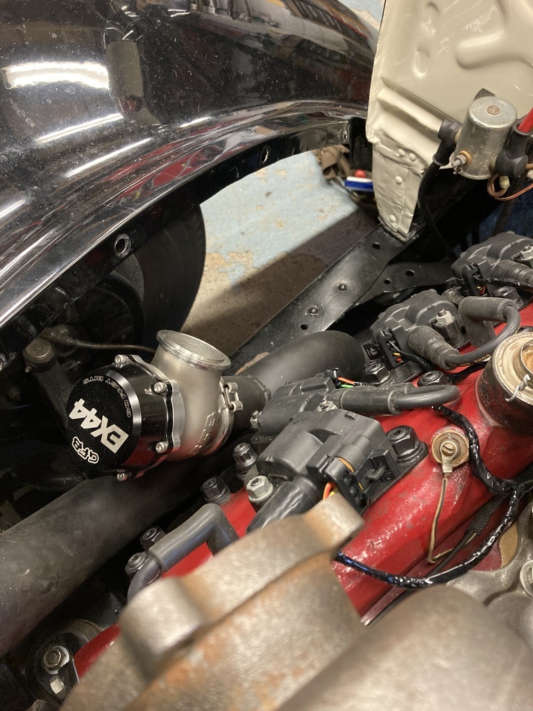 Now, I could just run it without the panel which would mean all the water and curse word off the road entering the engine bay but worse is the panel ties a lot of the other panels together and these cars are terrible for stress and fatigue cracks at the best of times so losing so much support was going to be disastrous in the long term. 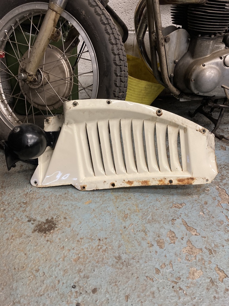 Cutting up my original panel was out of the question. I thought about making a copy of the panel with the necessary clearance but it’s a complicated thing to copy. This left me the only option but to try and source a sacrificial replacement. I’d been down this route before with no luck sourcing one in the past. I tried one more time before having to bite the bullet of shipping one from the US. I got lucky the second time!  I also got myself a pile of exhaust bends to get started with.  A quick mockup showed the exhaust would end up in the back corner, which suited things nicely. The panel got chopped. 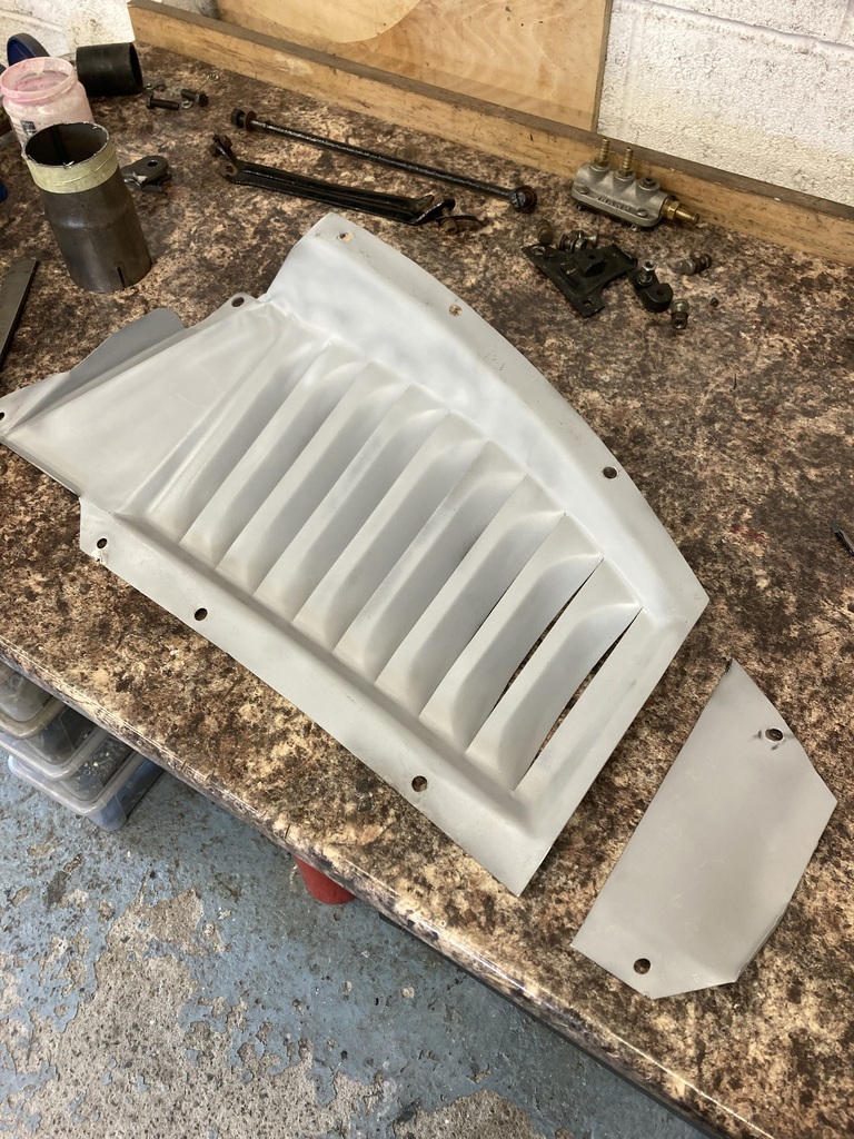 I only lost 2 of the least important fixing points. I also remembered to drill the horn mounting holes. 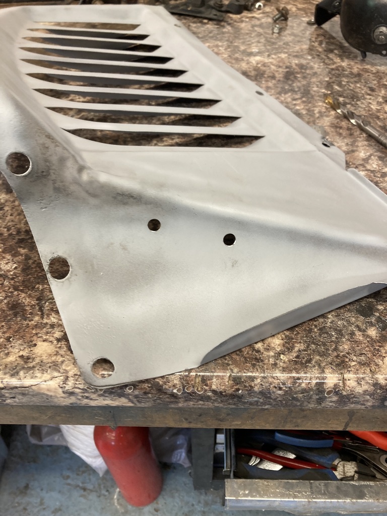 Bolted up it still wasn’t enough clearance to be comfortable. 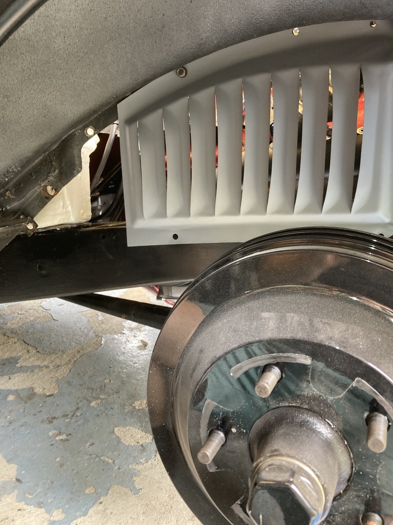 Back off I took another cut, the furthest louvre. 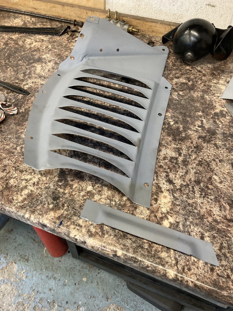 Which gave a more comfortable space to work with. 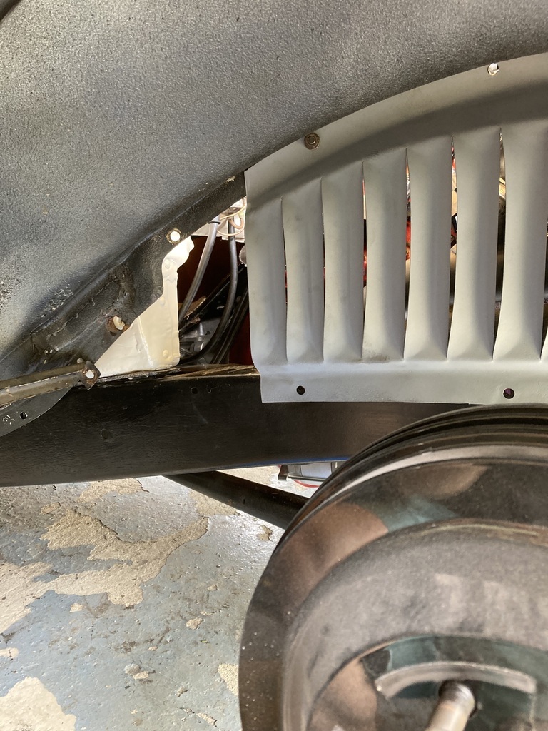 I could then lay out the first section of exhaust. 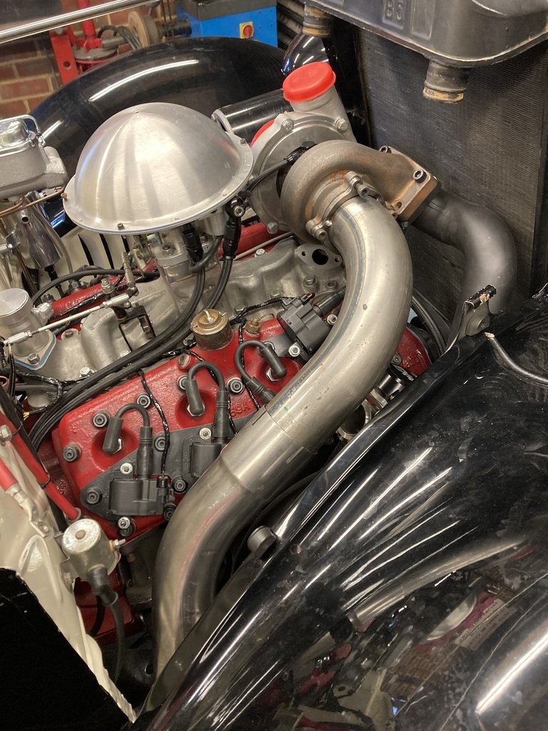 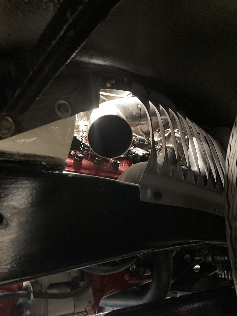 A short, straight section was added to get me beyond the chassis rail and into the arch.  I was tempted to pretty much finish it here but the novelty of that would wear off in about 10mins. I didn’t take it much further, managing to squeeze a stubby silencer under the arch.  There end the exhaust system! |
| |
Last Edit: Jul 28, 2023 2:47:50 GMT by Enbloc
|
|
Enbloc
Part of things
Posts: 367
|
|
Jul 23, 2023 21:52:54 GMT
|
Thanks! Looks great. When’s the big start up?! James Soon... Very soon  |
| |
|
|
Enbloc
Part of things
Posts: 367
|
|
Jul 21, 2023 22:22:28 GMT
|
Moving onto wiring the 8 individual ignition coils. Each coil has 4 wires going to it, a live, signal (ground) and 2 grounds. This would start to add up fast so I made the decision early on to have the coil wiring on another sub loom. The supplied lengths weren’t going to be enough so I had to order more wire. The pre-made loom used modern-ish high amp, thin wall insulation cable, so I ordered the same. 1mm black for the grounds and 2.5mm red/yellow for the lives.  The 3 metres of black I purchased were quickly swallowed up before I’d even managed to complete one side! 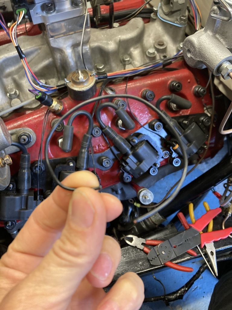 The lives to the coils would be paired as they made their way back to the main feed. The pairing is different on each bank to try and avoid pairing coils/cylinders that fire consecutively. I don’t know if this is needed but it seemed the right thing to do. I ran the lives and had a real battle trying to crimp and fit the the 2.5mm into the terminals and plugs. 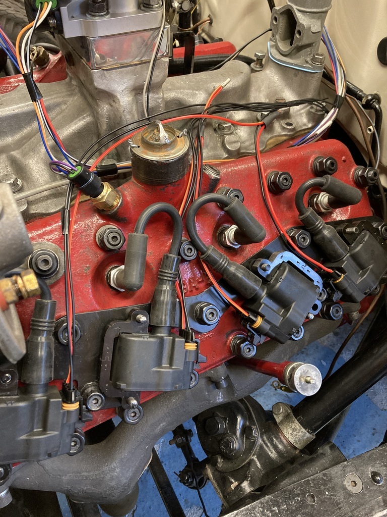 After completing one side I realised where’d I’d gone wrong and why it had been such a struggle. The crimp terminals, seals and plugs are only really designed for 1mm wire, so forcing 2.5mm through everything was way overkill for the individual coil runs. I decided to scrap what I’d done but what I had done had used up the supplied terminals and seals and the terminals were also locked into their plugs. I needed to unpin the terminals which meant finding a crappy old screwdriver in the bottom of the toolbox and grinding the end into a pokey tool.  Which worked a treat. 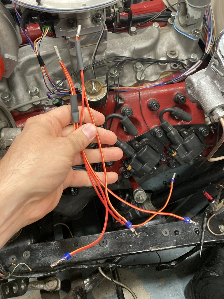 Another order was placed for yet more wire, all 1mm this time and a packet of replacement terminals and seals. 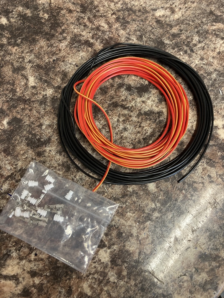 I revisited the grounds I’d run. Having 8 individual grounds on each bank was stupid so I paired these up as well leaving me with a more manageable 4 which I could squeeze into a single ring terminal that is bolted down under one of the inlet manifold bolts. 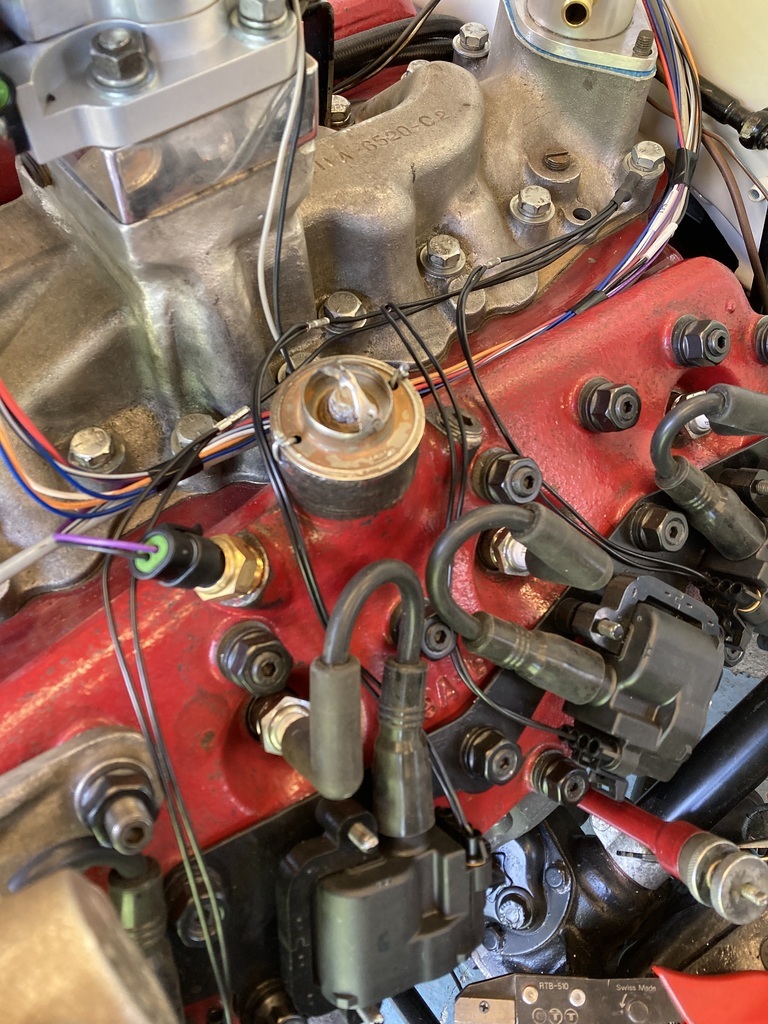 The lives redone in 1mm went much cleaner.  A further development of the idea of a separate coil loom was the idea of being able to disconnect it at the firewall. Removing the engine in the future should mean unplugging the sensors and unplugging the coil loom as a whole which would stay with the engine. 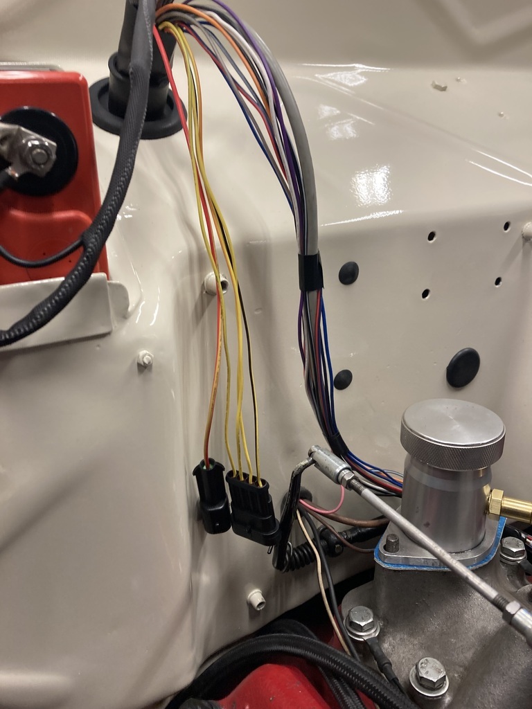 The main feed is on a single 30amp plug and the signal wires on smaller 16 amp 4 pin plug. 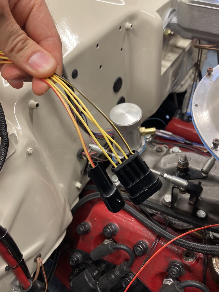 With the plugs positioned I could finish running and connecting up the lives. 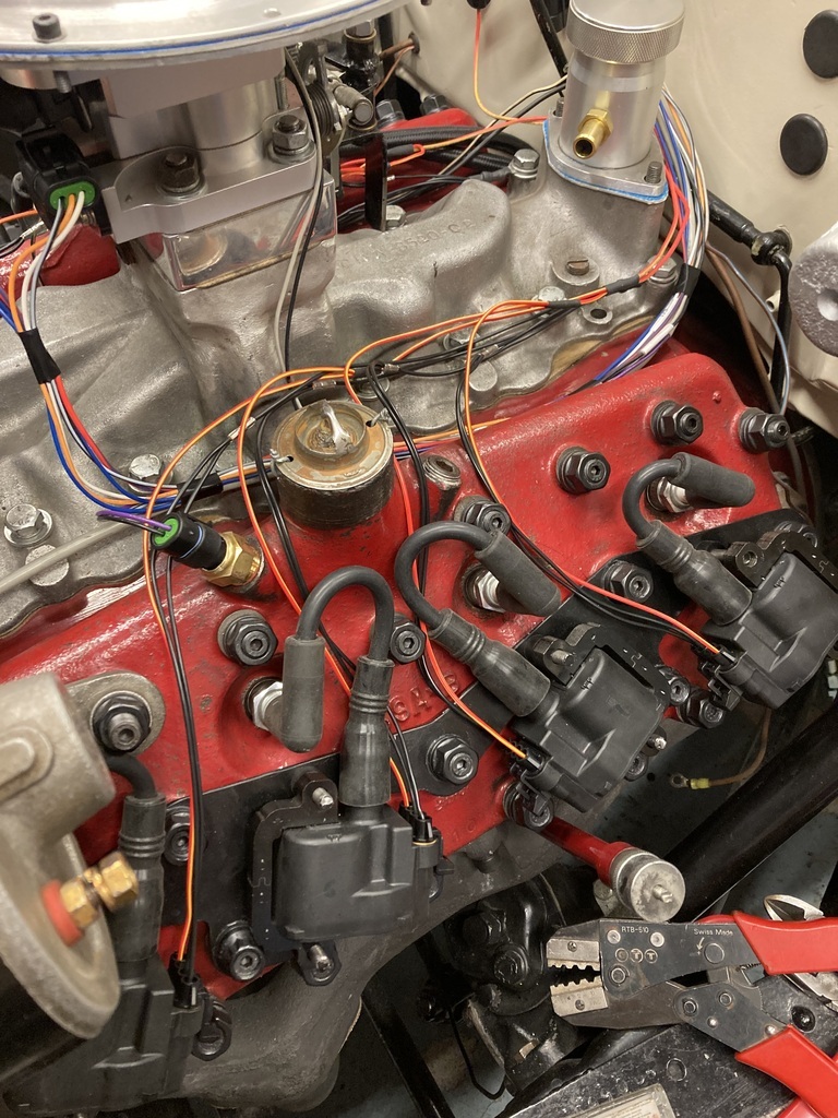 The signal wires had a little more complication to them. As already shown there are only 4 coil drivers but I have 8 coils! The work around to this is a wasted spark system where 2 coils are wired from the 1 driver. Obviously you want one cylinder to be on the compression stroke and the second paired cylinder to be on the exhaust stroke. This is dictated by the firing order of the engine and means each signal wire is running from its source and cross crossing to each cylinder bank. 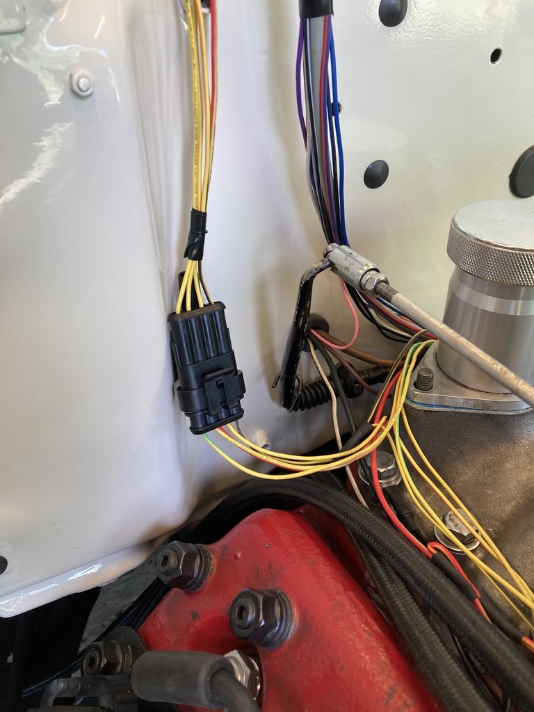  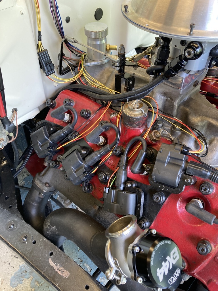 With (hopefully) all the wires taken care of everything was bundled together. 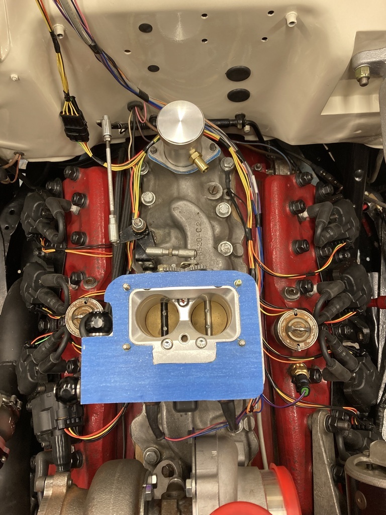 And removed…. 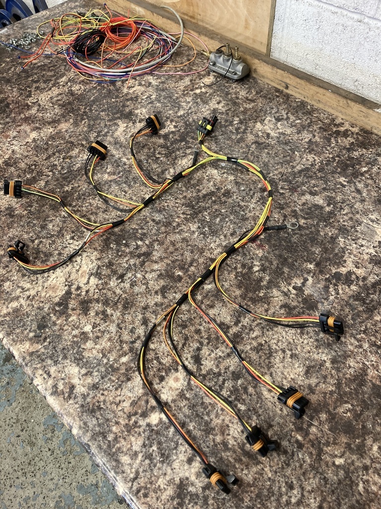 … for wrapping. 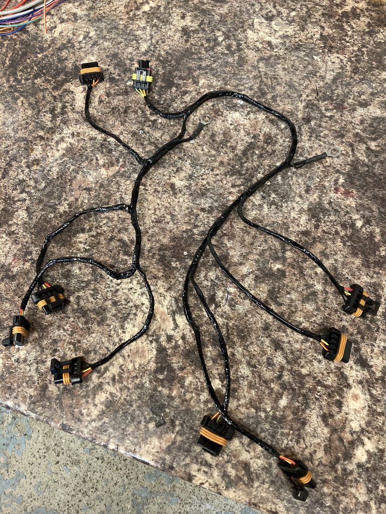 Back in place everything else was tidied up to complete. 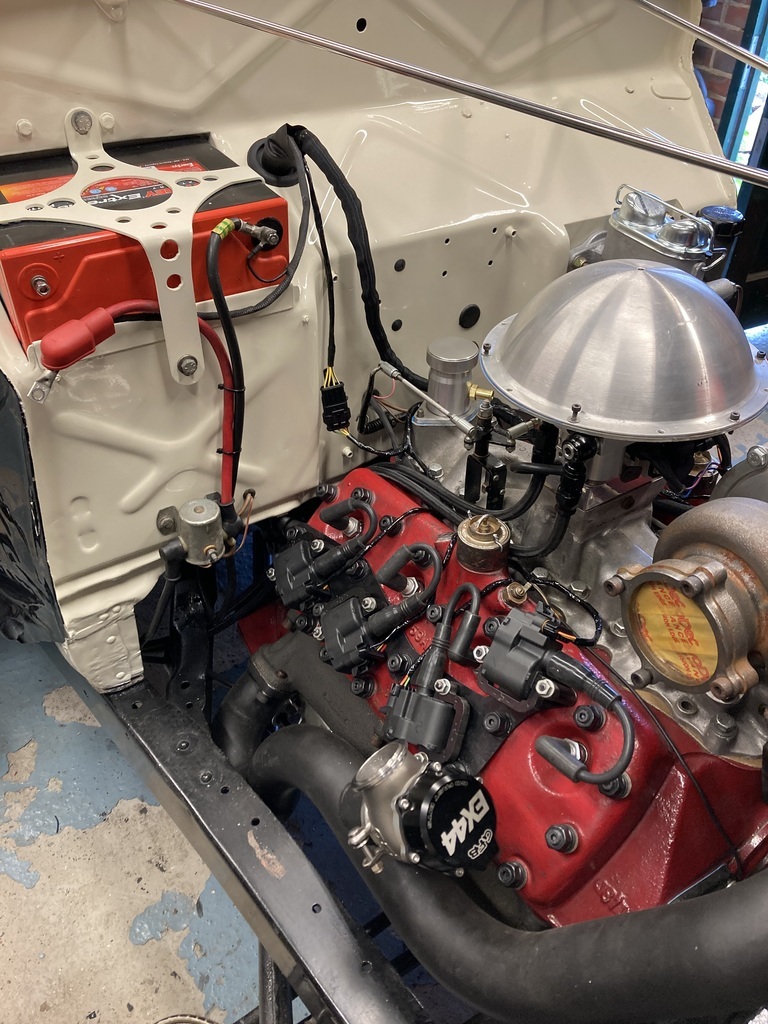  |
| |
Last Edit: Jul 21, 2023 22:28:00 GMT by Enbloc
|
|
Enbloc
Part of things
Posts: 367
|
|
Jul 19, 2023 18:26:25 GMT
|
Good stuff so far. What's the plan for covering the loom? Thanks. Nothing special, just loom tape or wrap. |
| |
|
|
Enbloc
Part of things
Posts: 367
|
|
|
|
Before running the new wires I thought I should deal with the old ones first. These are obviously part of the original loom which is still present. Some would need to stay like the sender wire but others could be removed like the coil and rev counter wire. 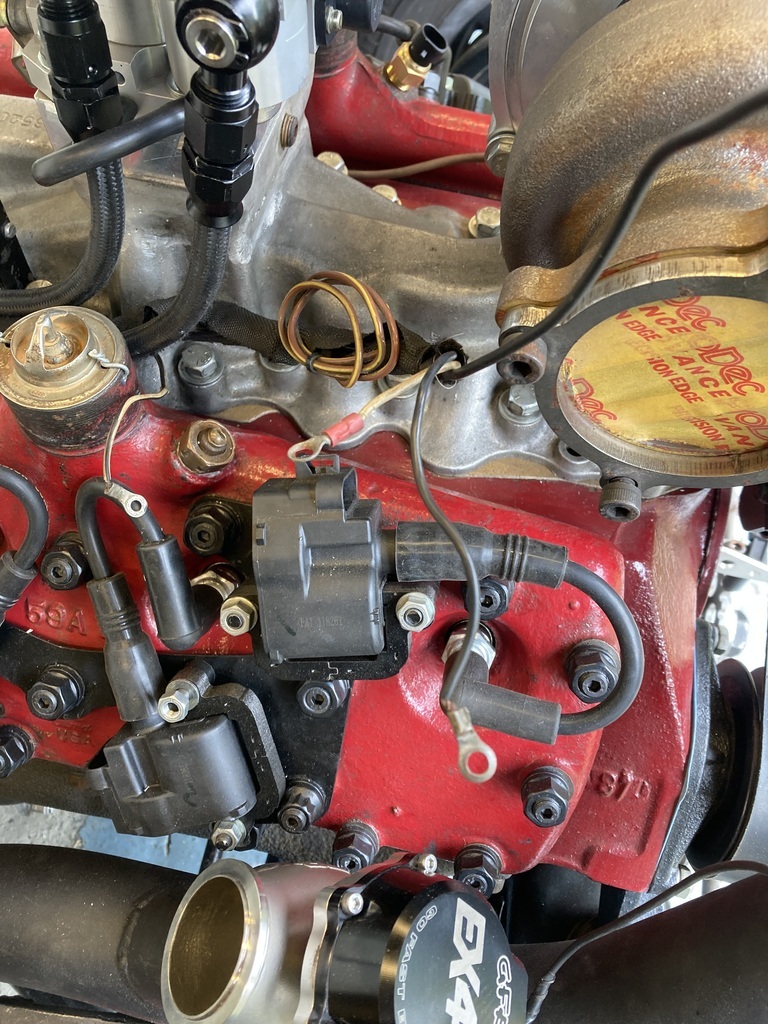 These were pulled back through and coiled up behind the dash for possible future use or reinstatement.  Starting off easy, main feed and ground run straight to the battery.  I dug out all the various plugs for all the various sensors and injectors.  All these plugs take terminals that need the heart shape crimp. As I had so many to do I bought myself some new crimps. I tried them on some bigger terminals I had spare as practice and everything was good. 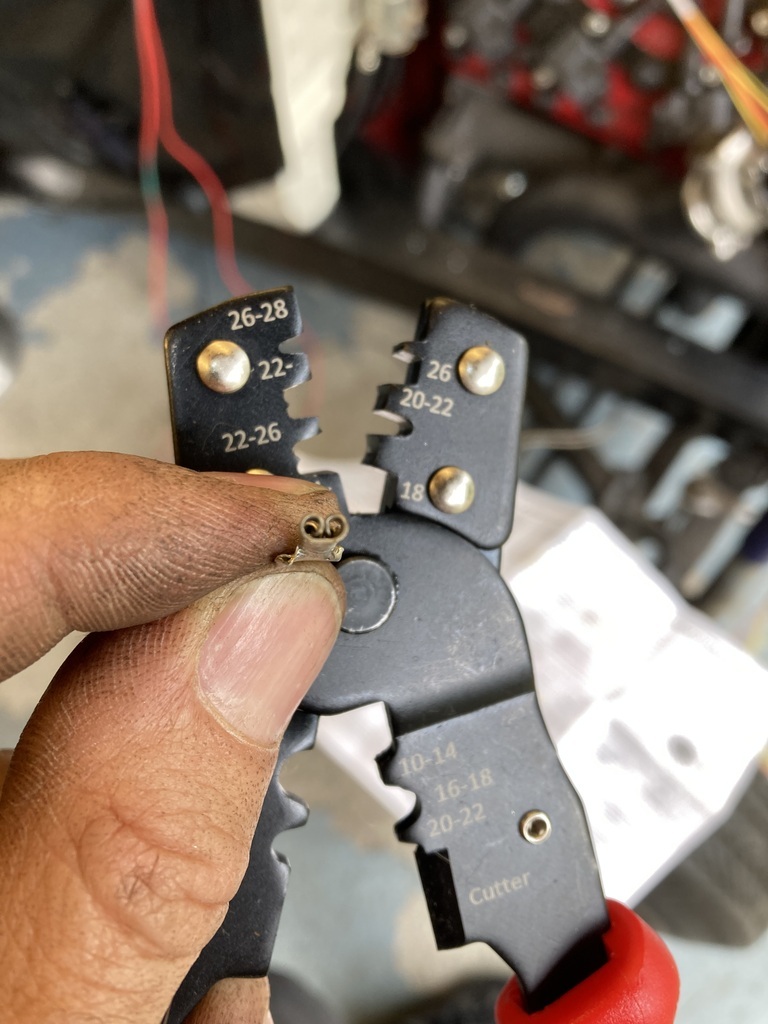 Starting with water sender I crimped the first terminal and completely bongo’d it beyond any usable state. Tried a second one and had the same outcome. 🤬  Came to the conclusion that my new crimps were absolute dog s**t on the smallest crimp jaws. Annoyed and frustrated I tried some multi crimps that were in the electrical box and they actually gave a half decent crimp, so continued with those.  I went to clip them into the plug housing and they didn’t want to go. When in doubt consult the instructions. Doh! On this style of plug the wire goes through and the terminal is pulled back into the housing! 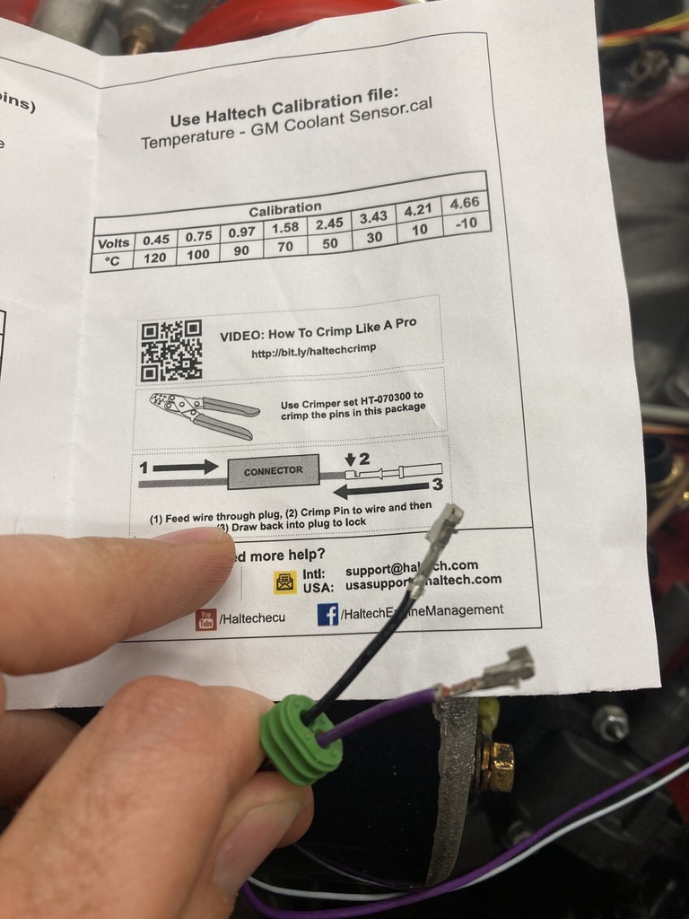 Second or is it third attempt?  Success! My first completed weatherproof plug. 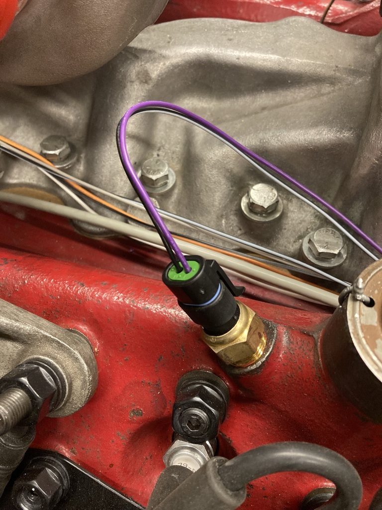 Throttle position and air temp completed easily.  And the trigger wheel pickup.  Injectors next. These would need the single live split to each injector and the individual signal (grounds) wires. 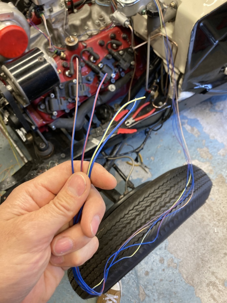 I only needed two of the supplied signal wires so the unused ones were pulled through and de-pinned in the name of neatness. You might notice there is actually 4 wires here? The loom covers 2 levels of ECU so actually has 6 injector wires pinned and run in the loom, even though the wiring diagram only shows 4. 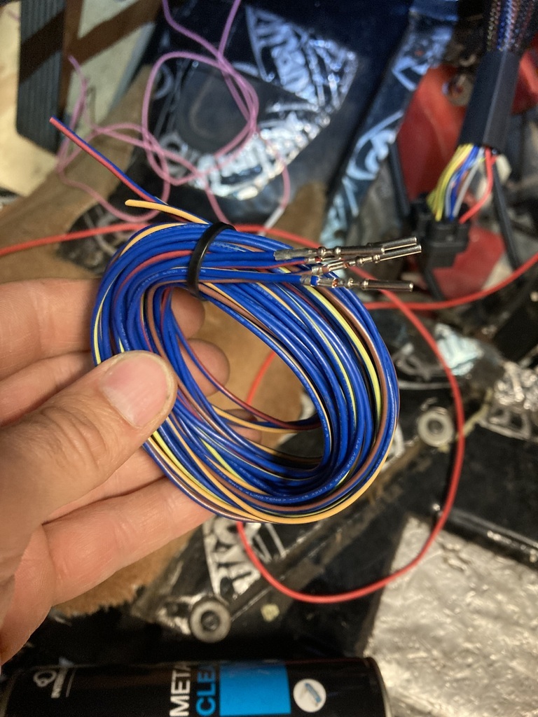 Completed. 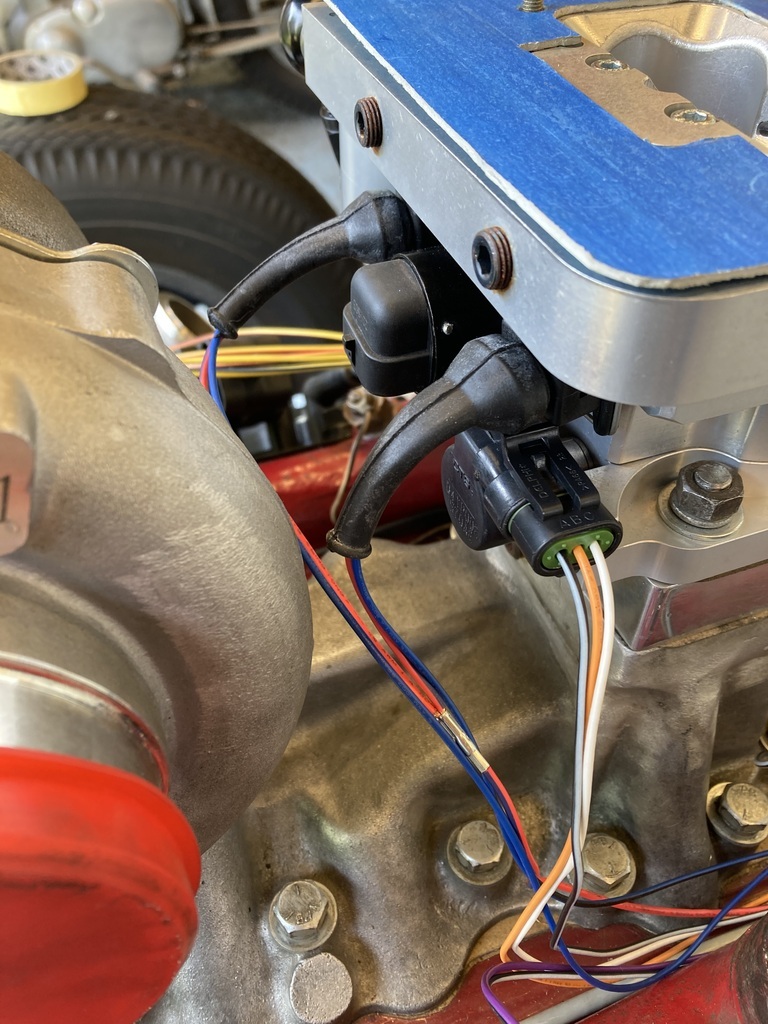 There was an ignition live that needed connecting. I remembered that I had just removed the old coil ignition live from the engine bay so this got repurposed already with a change of terminal.  |
| |
Last Edit: Jul 19, 2023 1:20:31 GMT by Enbloc
|
|
Enbloc
Part of things
Posts: 367
|
|
Jul 11, 2023 20:58:24 GMT
|
When I purchased the Haltech ECU I also got one of their pre-made looms. 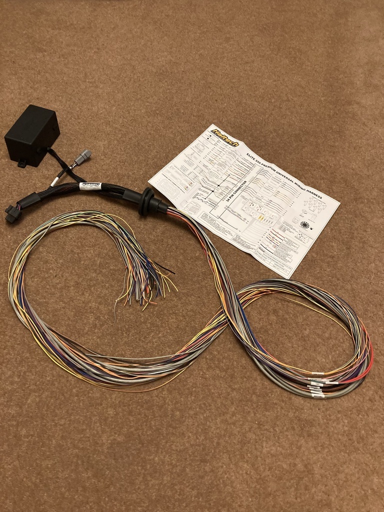 They have two loom options a basic loom and the deluxe loom that has the auxiliary fuse and relay box. I had the deluxe version as it was always my intention to have all the new engine wiring to be on its own loom and fuse box, leaving the current car loom intact and untouched. In hindsight I would have been better off with the basic loom as I’m only using one relay in the fuse box even that I could have got away without using. I thought about swapping it out but it was there and I wanted to get going with it so just carried on with what I had. Out the box the loom is quite a lump but I knew alot of this would be going in due course. I initially got a bit lost trying to identify and follow what I did and didn’t want to keep. The answer was actually starring me in the face the whole time. Each function had already been bunched and labelled! 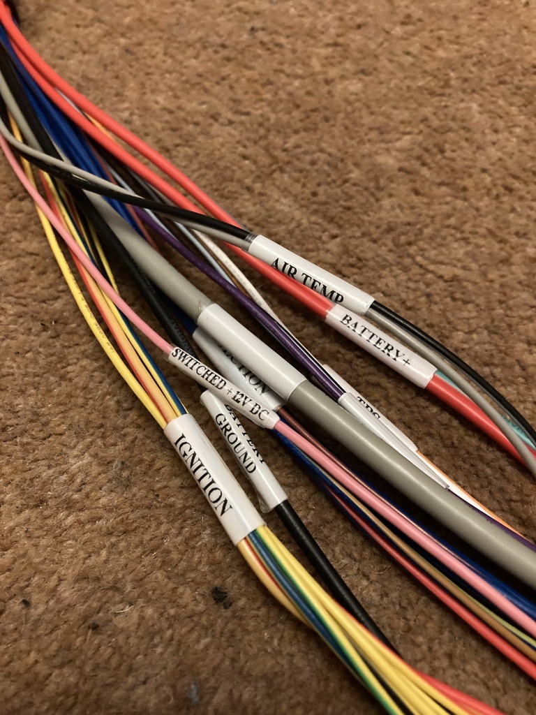 Off and running now I split off the ones I would need, which are on the left.  The ones I didn’t need or I think I didn’t need were pulled back through the loom. 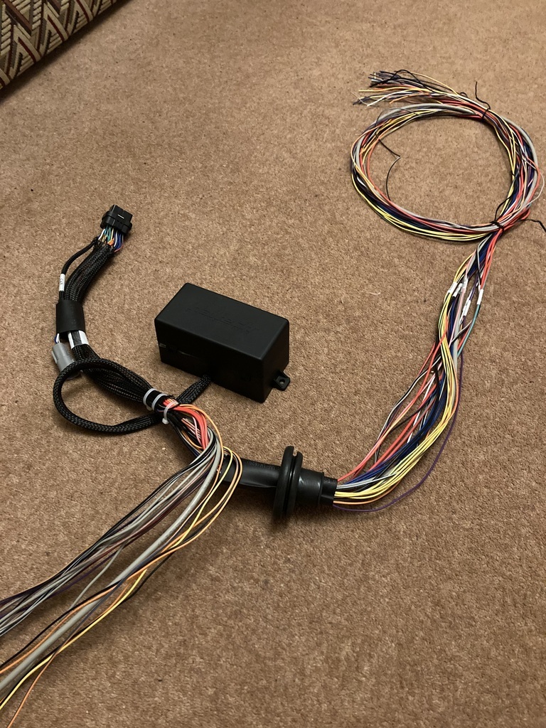 With most of the wires making their way back to the main 34 pin plug, any that aren’t needed can simply be de-pinned and pulled back out the loom. If in the future they are needed then can be re-pinned. Using the excellent supplied instructions and wiring diagram the correct pin is located and releasing the lock tab on the plug the pin can be pulled free and the lock tab pushed closed again.  What I didn’t account for was the common feeds and grounds were actually piggy backed within the loom which complicated matters a little with removing the unused bundles. 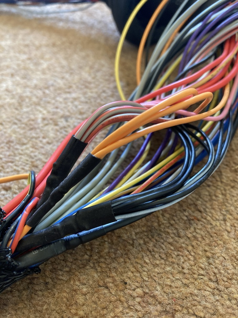 The grey/red bundle are 12v feeds, the orange are 5v sensor feeds and the black/white are grounds. The only way forward with this is to cut them. Not something I was happy doing but not the end of the world to reattach if needed. 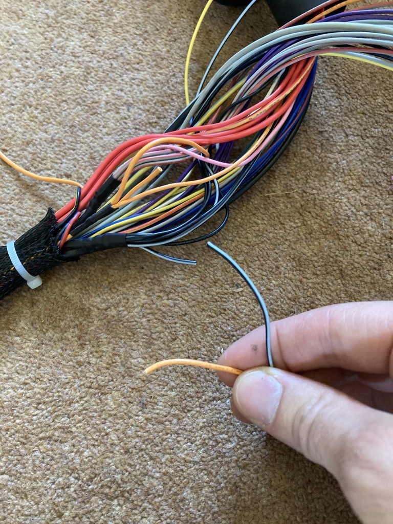 As they say, the first cut is always the hardest and with that out the way there was no stopping me! 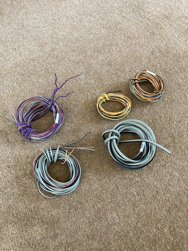 Things are looking much more manageable now. The rolled up orange wire is a heavy feed wire for a fuel pump, which I don’t need but it’s hard wired into the fuse box and I didn’t fancy cutting it so it sits there now or until I get fed up with it and cut it back! 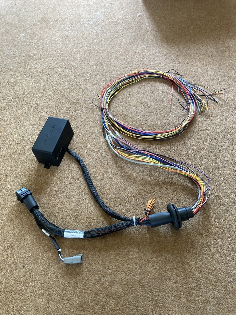 The loom could now be moved to the car. I needed to locate a hole in the firewall for the loom to feed through. Again looking for a position that missed fixed objects and also wanting to keep it tucked up behind the dashboard. 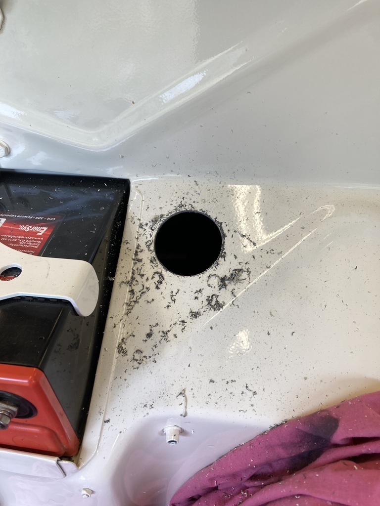 Mmm… Taking a 2” holesaw to a freshly painted firewall. Firewall grommet fitted and wires pulled through. 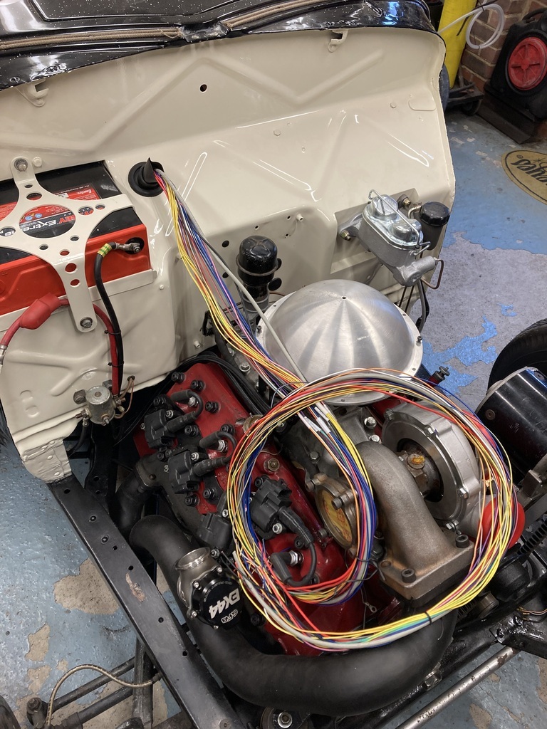 Before I started running the new wires I cleaned up the old wires that I wouldn’t be needing. This consisted of the coil wire, rev counter signal wire and a rolled up wire that I’m even sure what it’s for? Maybe an unused warning light?  These got fed back through the firewall and rolled up so they can be reinstated in the future if needed. 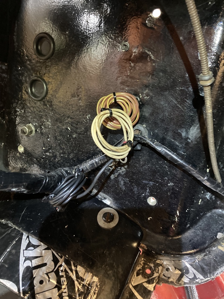 Starting to rough out the wire runs. 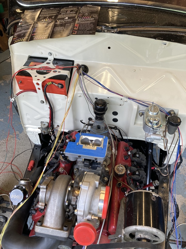 |
| |
|
|
Enbloc
Part of things
Posts: 367
|
|
|
|
Well, I can’t put it off any longer. 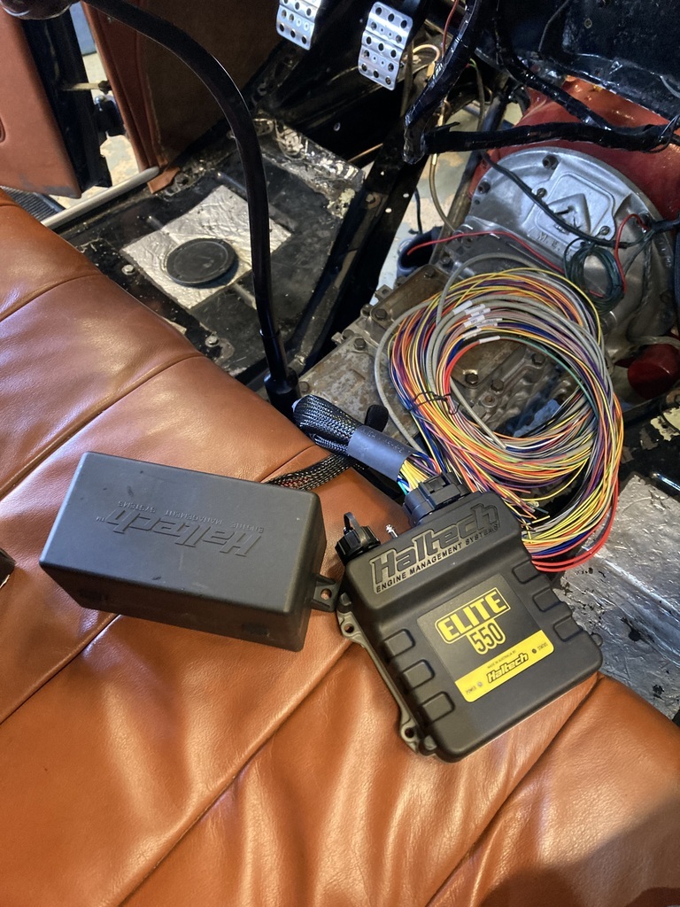 A home was needed for the ECU and also the auxiliary fuse/relay box that I had specified with the pre-made loom. I wanted to put the ECU on the passenger side as there was slightly less junk on that side to contend with but I still had the wiper motor, the backside of the battery box and that bloody Lincoln Zephyr dash centre section to contend with. This only really left two workable areas the glove box and the footwell. The footwell was ruled out as it would put everything on display, I would have to takes chunks out of the carpet and would be generally more prone to be kicked and bashed. So, the glove box it is. 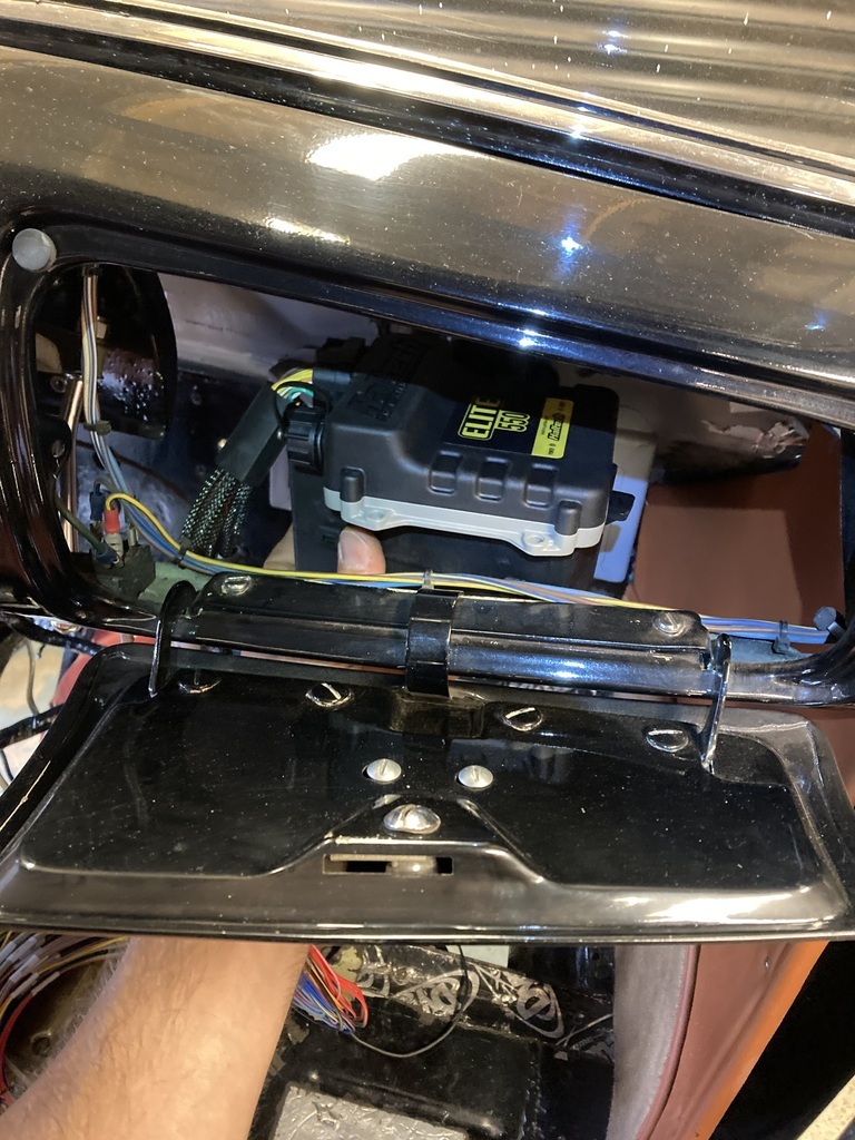 Things were made easier mounting the ECU here as there wasn’t any box here anyway. Smoke and mirrors and all that. Using CAD I started to mock up a kinda shelf arrangement that would pick up on the existing glove box door hinge fixings and a third fixing point tucked up behind the dash front. The ECU would sit on the top side and the fuse/relay box would mount on the underside of the shelf.  The CAD was transferred to some 2mm aluminium. 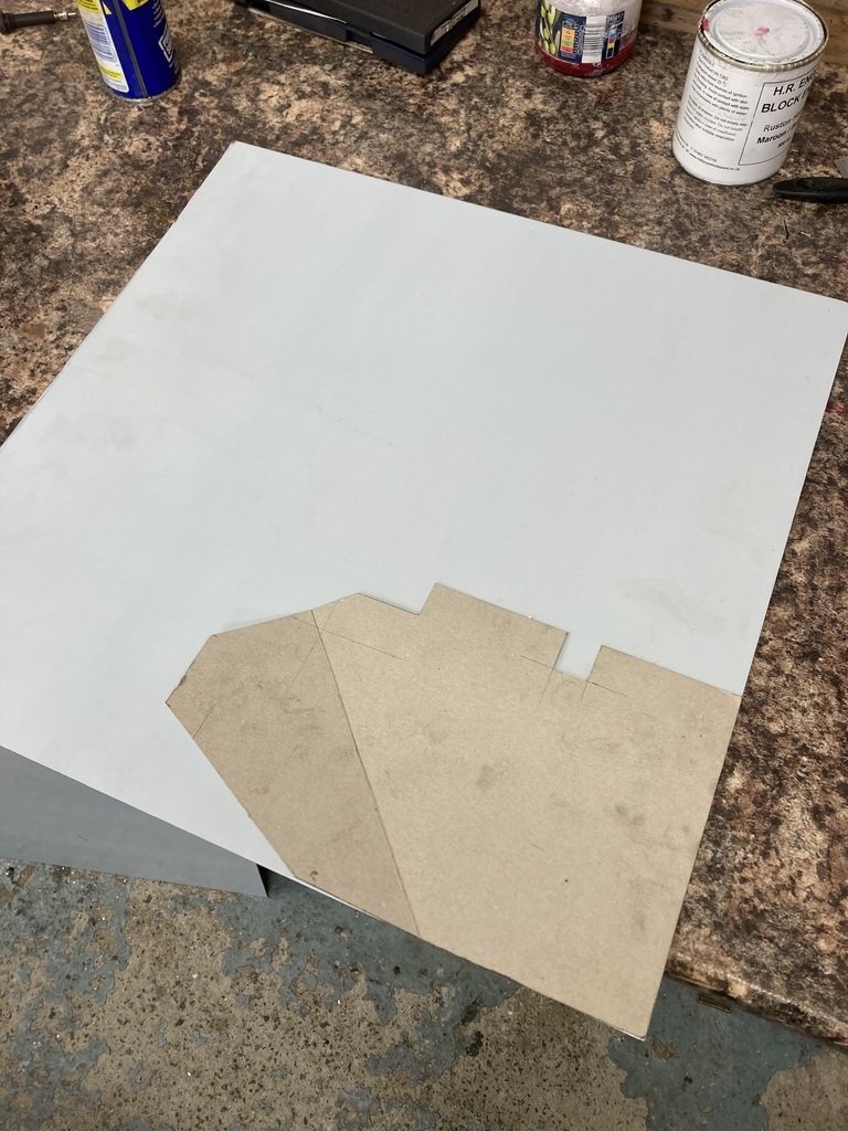 Cut out the panel had the fold put in with my hokey bench top folder. I thought it would struggle with the 2mm but it worked fine. 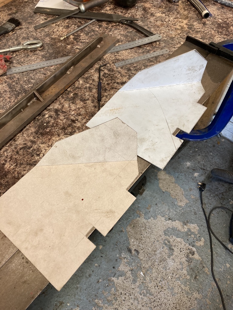 I purposefully left excess material because it needed a series of whoopdies to weave around and line up to various faces with all the different angles. Any excess was removed at the same time. 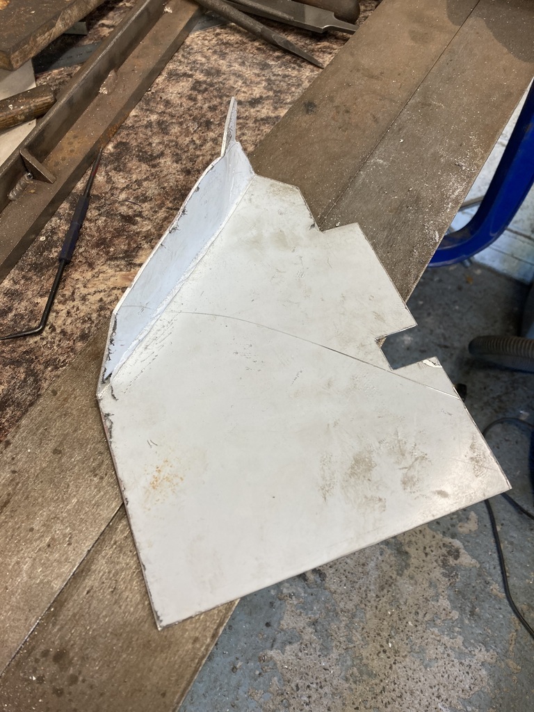 The original fixings were 10/32” unf. They would now be too short with the extra added layer. Digging through the oddments box found me a bag of these raised countersunk 10/32” screws which proved perfect as they were the right length and I could reuse the old hardware. The panel was drilled and countersunk for the fixings.  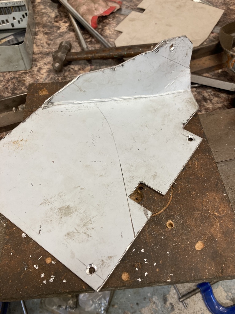 I needed a way of fixing the two components. Luckily the fixing points for both were completely opposite to each other so nothing clashed but because of each component being mounted in opposite directions meant any sort of captive nut would stick out on the opposite side and look rubbish. In the end I just went with simply tapping the panel for the same raised countersunk screws which were cut down so they were flush when fitted. 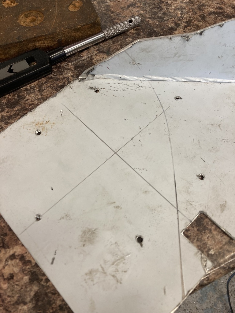 All mounted ready for a trial fitting. 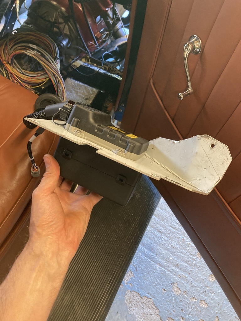 Ahhh, my eyes! Trial fitting successful the protective plastic was removed. This wouldn’t do so it was scuffed and spray bombed. 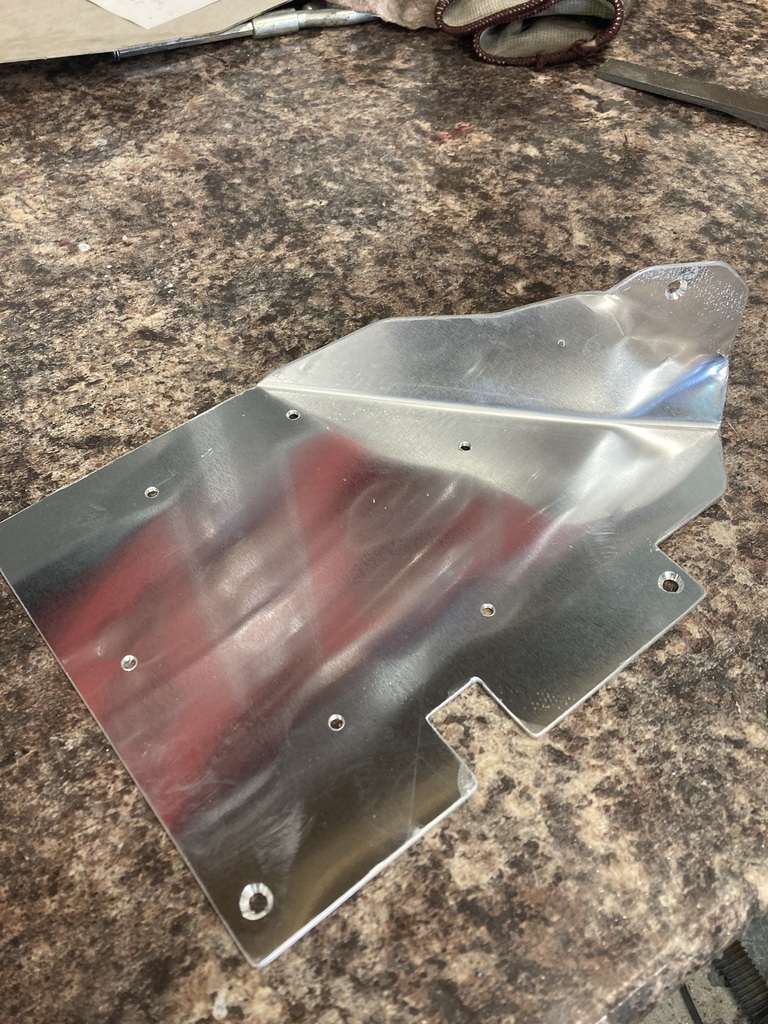 Final fitting. Now you see it… 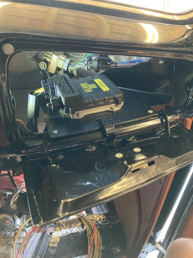 Now you don’t. 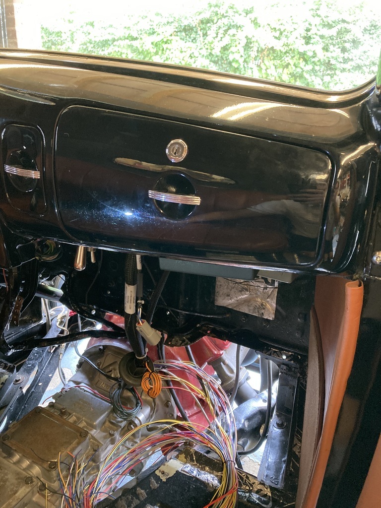 |
| |
|
|
Enbloc
Part of things
Posts: 367
|
|
|
|
The stiffness of a bar in torsion is based on the polar moment of area and it's material properties, the material properties are constant but for a round bar the polar moment of area is based on radius^4 so a small increase in radius can massively increase the stiffness. as an example in rough terms going from a 15mm to a 18mm bar doubles the stiffness. Ah, torsion not tension, as I said. 😁 You’ve perfectly described what I was trying to! |
| |
|
|
|
|
Enbloc
Part of things
Posts: 367
|
|
|
|
Forgot how much I love this thread, just read it from the start, and being an ex (read retired) night shift engineer, I'm up with the sparrows fart, so I have peace and quiet to read, one thought that crossed my mind about your Sierra ARB,..... make a supplementary ARB to sit under the original, mount it like angels and cortina did slung underneath on piggyback brackets EN24T will work well, and by working out CSA you can work out how big you need to go. IIRC you can hot bend it and don't need to heat treat. Thanks from another night shift engineer! It’s the reason a lot of my posts appear in the early hours of the morning. 😁 The piggy backed ARB was always an option but I’m only looking for a relatively small increase in size 1/8”-1/4”. I don’t know what that increase in bar size works out cross sectional area wise into its own bar? But then does the bar have different tension characteristics because of the extra material being at 1 1/4” or 1/2” diameter for example? There are a lot of variables in ARB characteristics and I don’t think you can ever truly work it out, same with brake master cylinder size! |
| |
|
|
Enbloc
Part of things
Posts: 367
|
|
|
|
If it’s any consolation, I’ve just had to remove 200 screws and slide two glued together sections of floorboard to fit a noggin underneath them that I’d forgotten, and remembered in the middle of the night last night. 🙄 I feel your pain. |
| |
|
|
Enbloc
Part of things
Posts: 367
|
|
|
|
Returning back to the belt. After making many improvements to the setup I still wasn’t 100% with it. 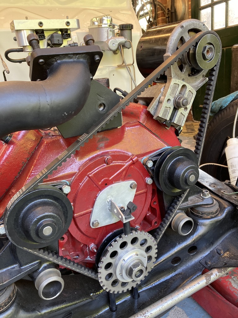 It was suggested by jimi and TessierAshpool that an idler may improve the situation which is of course correct and the idea had crossed my mind in the past but had gone no further. Two reasons inspired me to expand on the idea. First the turbo mount I fabricated gave me a large flat area to work off that was also pretty much in the middle of that long belt run and the second was that I realised that the turbo outlet actually clashed with the belt. The outlet might not end up here but it would mean one less area it can’t be positioned in. 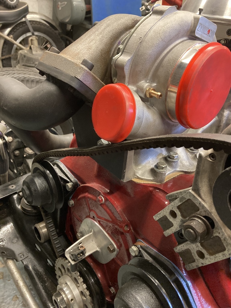 To find an idler. I remembered that the Pinto had a simple idler mounted to a backing plate. Looking these up for reference brought up another option which was even better. A Duretec idler. So… 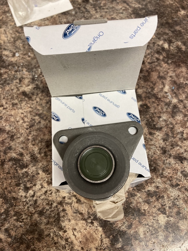 The weren’t much money but cheapest I found was direct from Ford via EBay. A quick mock up showed it was perfect in every way, even the spacing! 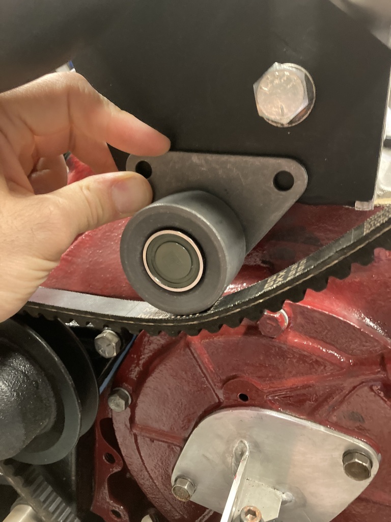 The mounting holes were drilled and tapped straight into the turbo bracket. 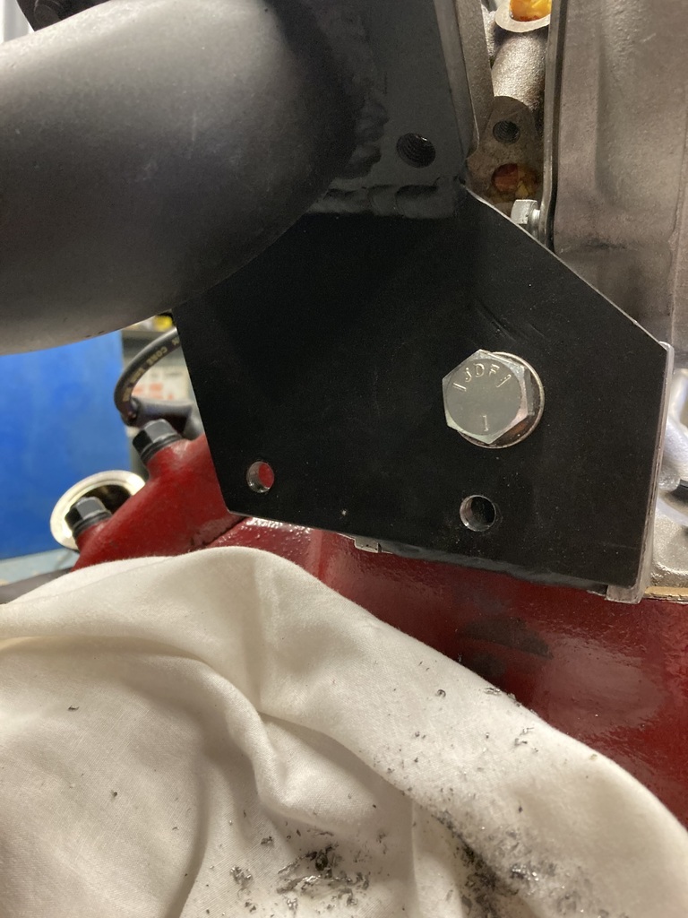 All mounted up. The long run has been reduced, the turbo clears and the belt is gripping the alternator pulley tighter now as well. I didn’t even need a longer belt! 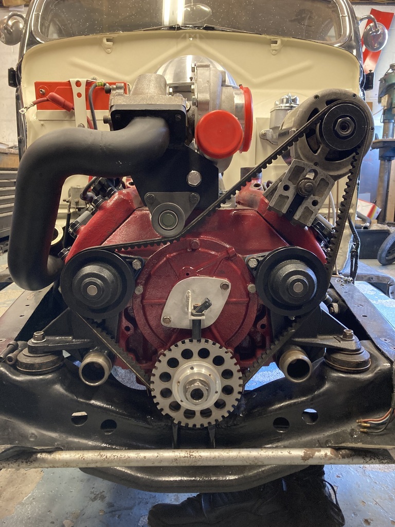 Trying to keep the progress going between the bigger jobs a nice filler was fitting the water paraphernalia. 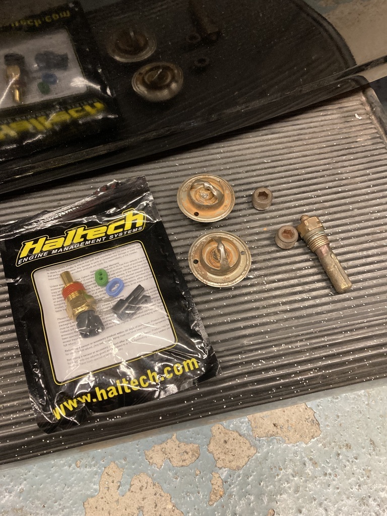 What I had was the water temp gauge sender, blanking plugs for the redundant holes and the thermostats all, again, robbed from the previous engine. A Haltech water temp sender for the engine management was also added to the set. I discovered a long time ago that Pinto/CVH thermostats were a good replacement for the expensive and very poor quality reproduction Flathead ones. The only downside is there is no way to hold them. 99% of the time just the top hose clamping around them is enough to hold them in place but they can come loose and spin in the top hose. 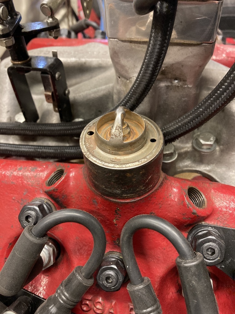 As a belt and braces I wire then in place. The thermostats are already pre-drilled from being previously wired but the water necks on the heads need drilling for the lock wire. 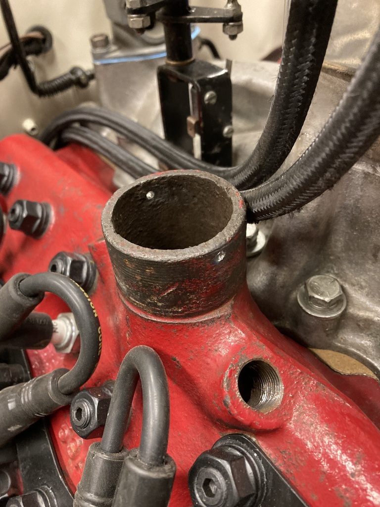 The wired thermostat and the gauge sender and blanking plug in place on the passenger side. This position is pretty much set as that’s where the wiring is run to. 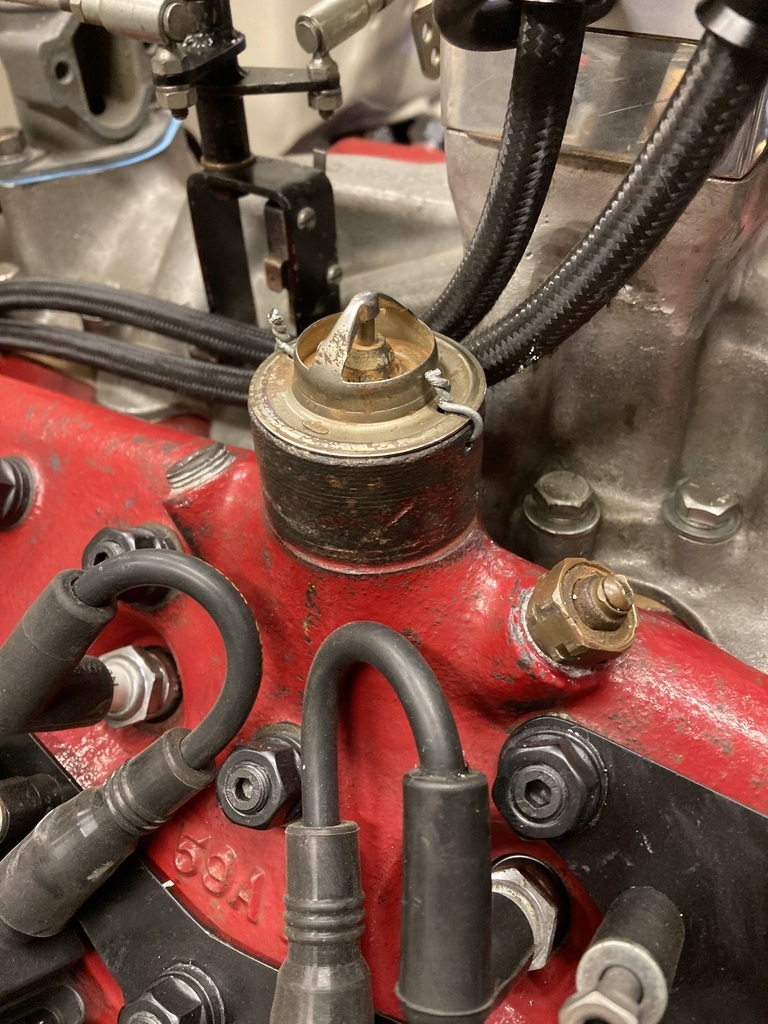 The driver side has the same with the added Haltech sender. This worked out well as most of the senders will end up in the area helping with loom runs. 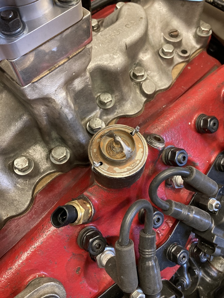 The turbo needed its clocking finalised so I could start thinking about plumbing pressure lines and drain backs. I dug out the “fitting kit” which had come with this £145 Chinese turbo. Up until now I hadn’t paid much attention. Here’s what I had from the top…😆 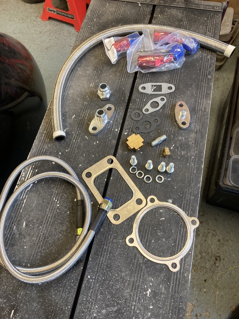 1/2 meter of -10 braided hose - it’s short length making it completely useless. A selection of -10 fittings - I maybe missing something with these but I see no means of them actually clamping a hose. A random selection of gaskets. A -10 weld on bung A drain back adapter and a restricted feed adapter A 4-way adapter with one male/male adapter and a blanking plug - these items do not mate up with any other items in the kit. Some fixing bolts Two steel shim gaskets And my favourite, A -4 braided pressure line that, again, doesn’t fit anything in the kit! So, most of that will be going in the bin! This was identified as the drain back port. 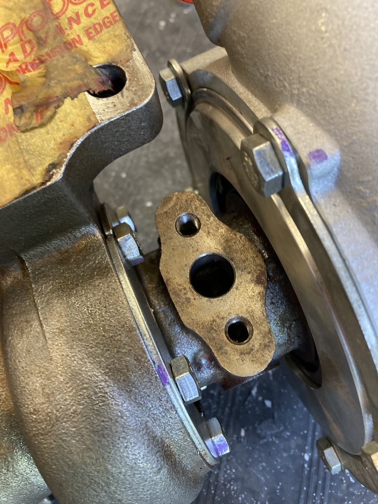 Which the drain back adapter didn’t fit. 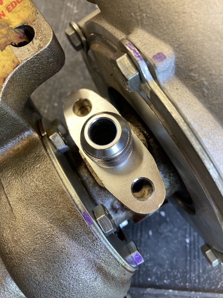 The restricted one fitted perfect it. 🤦♂️ 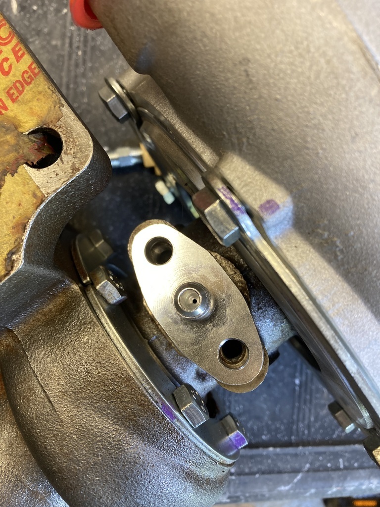 Apart from the mounting holes not lining up the rest of it was fine (kind of) so I slotted the mounting holes to make it fit. 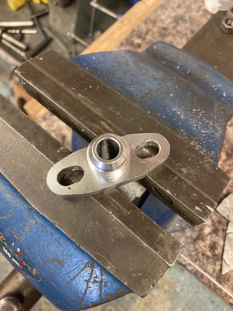 The centre hole was smaller compared to the turbos one so this got a heavy chamfer and then blended to remove any restrictions in the flow of oil. 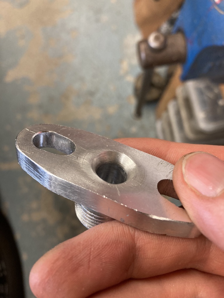 The inlet manifold had been torqued down for while when one night I woke up in a cold sweat. The reason being I didn’t remember blocking up the now disused PCV holes on the underside of the inlet. The next day I still couldn’t remember so had no choice but to take it back up again. 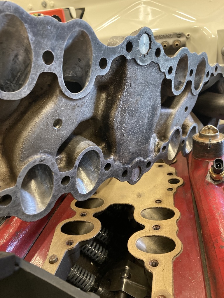 Luckily I did because, yep, they had been left open. That could have got messy. 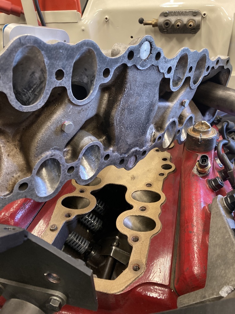 |
| |
Last Edit: Jul 4, 2023 1:36:41 GMT by Enbloc
|
|
Enbloc
Part of things
Posts: 367
|
|
Jun 30, 2023 19:26:21 GMT
|
The last job with the fuel lines was the connections at the throttle body. There was another issue with the banjo fittings. As well as hitting each other they also sat slightly high, 2 or 3mm maybe, above the top face of the throttle body. This was an issue because it meant the base plate to the carb hat wouldn’t sit flat. I had a few thoughts like dimpling the base but nothing really workable. Then I thought maybe an extra thick gasket could give me enough clearance? 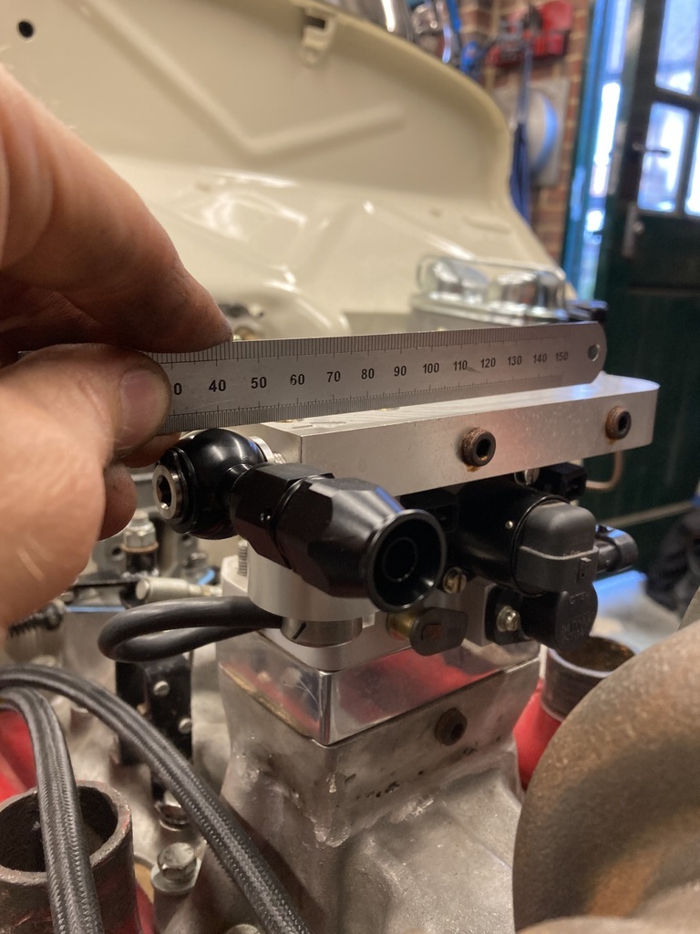 While I was there I discovered I actually had a second position option with the return line outlet. This worked out great as it eliminated the clashing issue with the two banjo fittings. But… The banjo didn’t actually line up with the port as it hit the throttle body top. This section was nothing but aluminium plate so no issues putting clearance in. 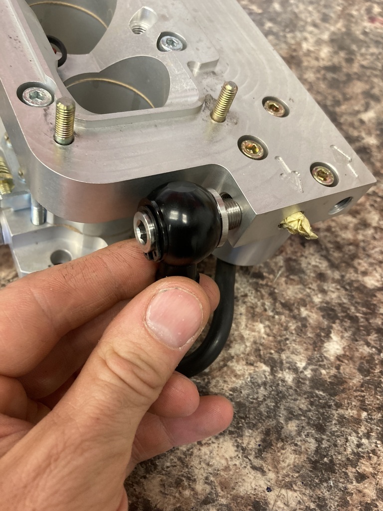 Another item to address that had been bugging the curse word outta me was the razor sharp inlet bore edges. 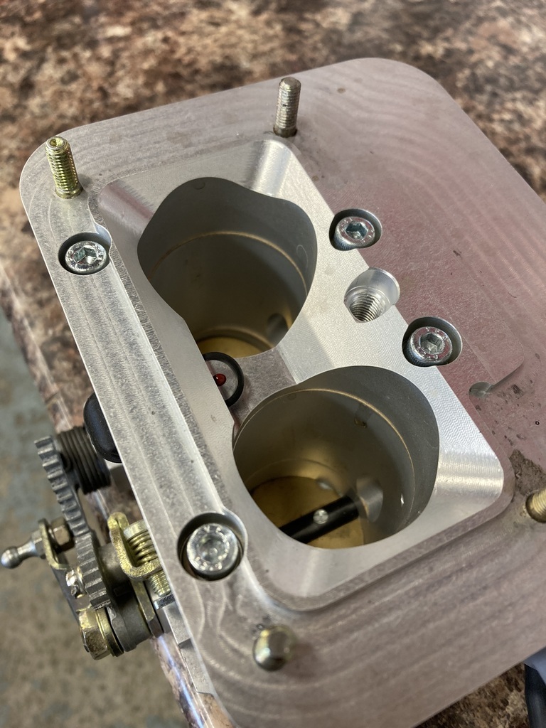 Apart it came. 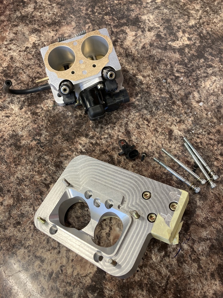 The first inlet done. 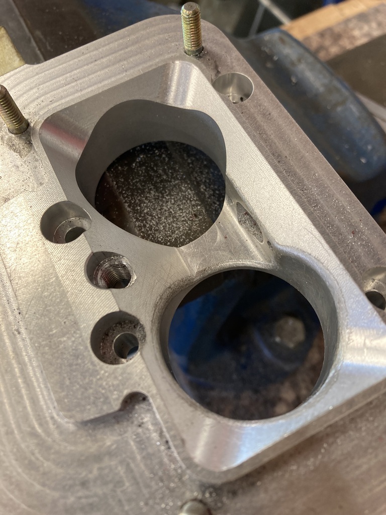 And the clearance added for the banjo. 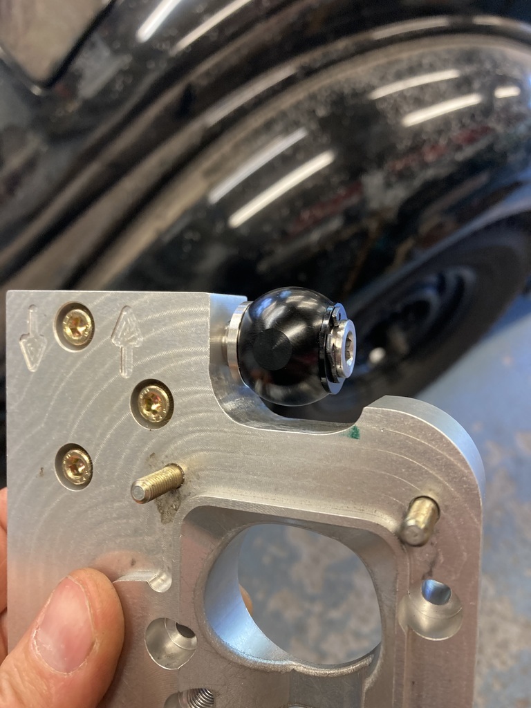 The finished top ready to go back on. 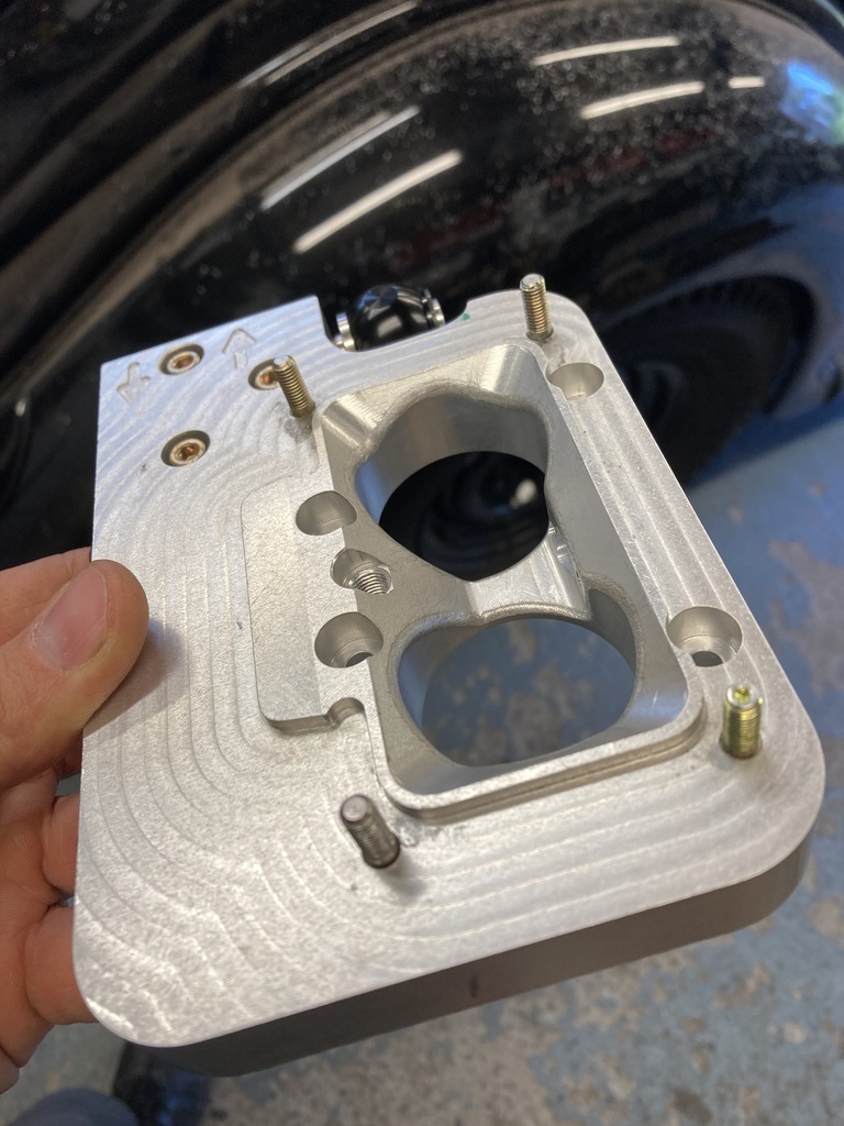 Another small issue to address was the gasket overlap between the middle section and the base plate. The overlap was bad enough but over the injector spray path as well. No. The base and middle got split apart. 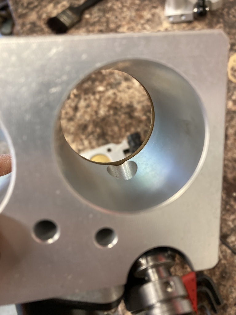 That’s better. The gasket is still there, I promise! 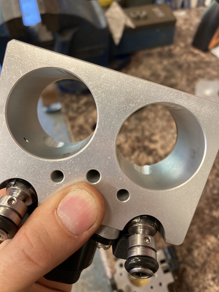 All done I reassembled the body and found something else. 🤦♂️ The screws that come in from the bottom of the base were sitting proud, only 0.5mm or so, but proud nonetheless. I guess they’d just squish into the gasket? Could I carry on living a normal life knowing they protruded 0.5mm? 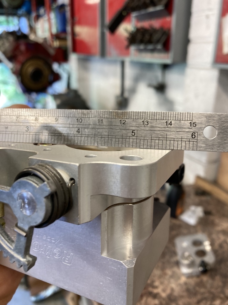 I removed the bolts and took a 0.5mm cut off the heads…  While this was going on I’d been waiting on my order of gasket material. I needed 3mm for the base gasket and around 1.5mm for the WW1 helmet as well. Remember the WW1 helmet carb hat? I looked at normal paper gasket material and the rubber impregnated cork stuff but it either didn’t come thick enough or was dubious to its sealing quality’s when expose to boost. I stumbled onto this stuff which is still paper based (I think?) but is sold as high temp and high pressure resistant and it also came in the thicknesses I wanted. 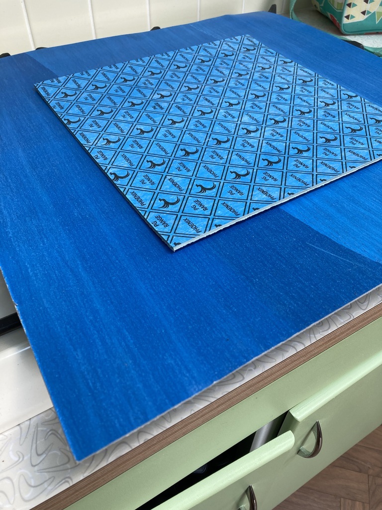 I started cutting out the 3mm gasket material with a Stanley knife. It was as slow and painful as you’re imagining it was. For the outside edges I used tin snips which worked surprisingly well. 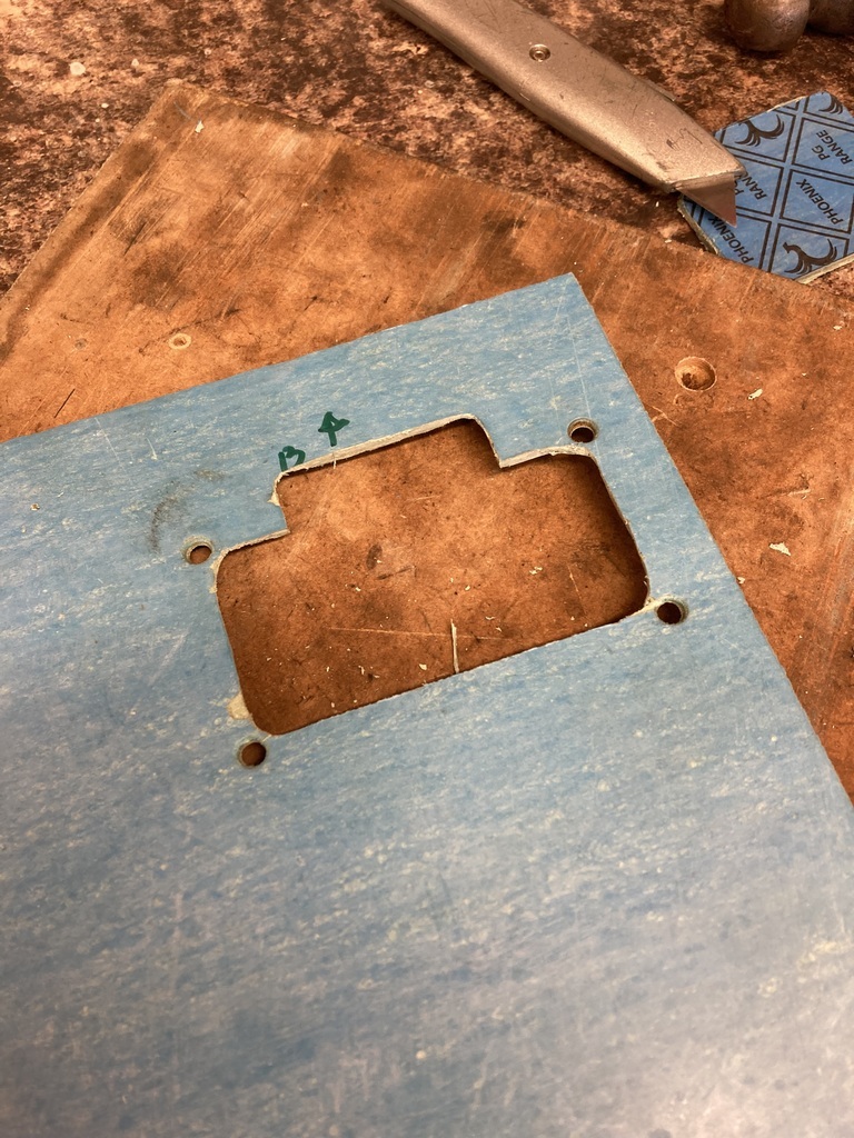 Fitted up, I didn’t like the way it fitted. It was too tall. 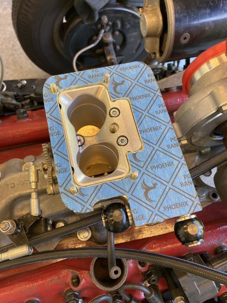 So, I remade it in the 1.5mm and everything fitted much nicer and I still had my clearance. 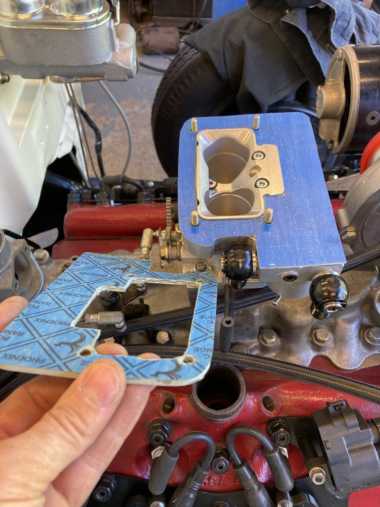 I needed a gasket between the carb hat base and carb hat/WW1 helmet. Tracing around the lid started me off with this. 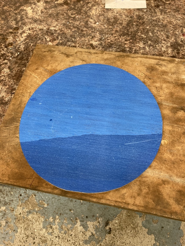 My compass wouldn’t go big enough for the internal circle so I had a look around for something the right diameter. Bet you can’t guess what I used?! 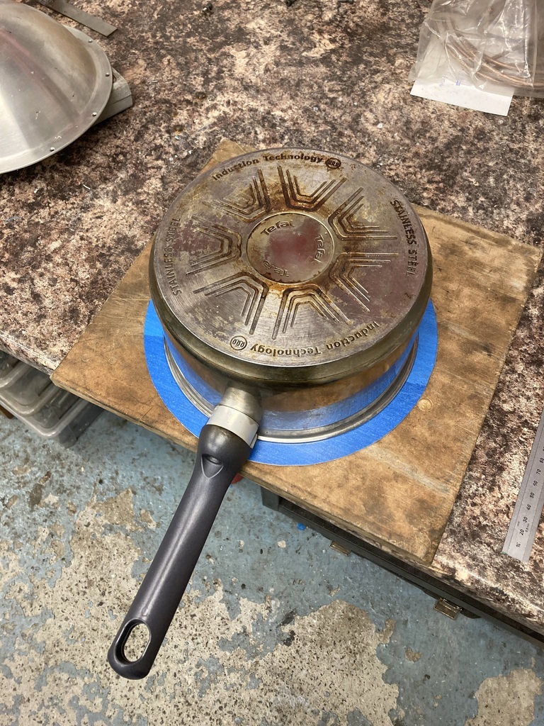 Cut out, I was left with this large ring. 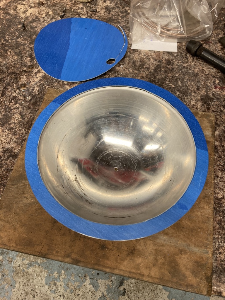 I needed to put in the 12 holes for the holding down bolts. I didn’t want to mangle it with the hole punch so thought I’d see how well it drilled on a scrap piece. Surprisingly well, actually. 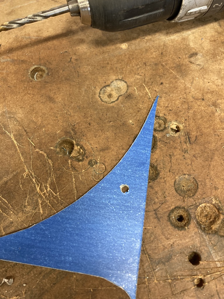 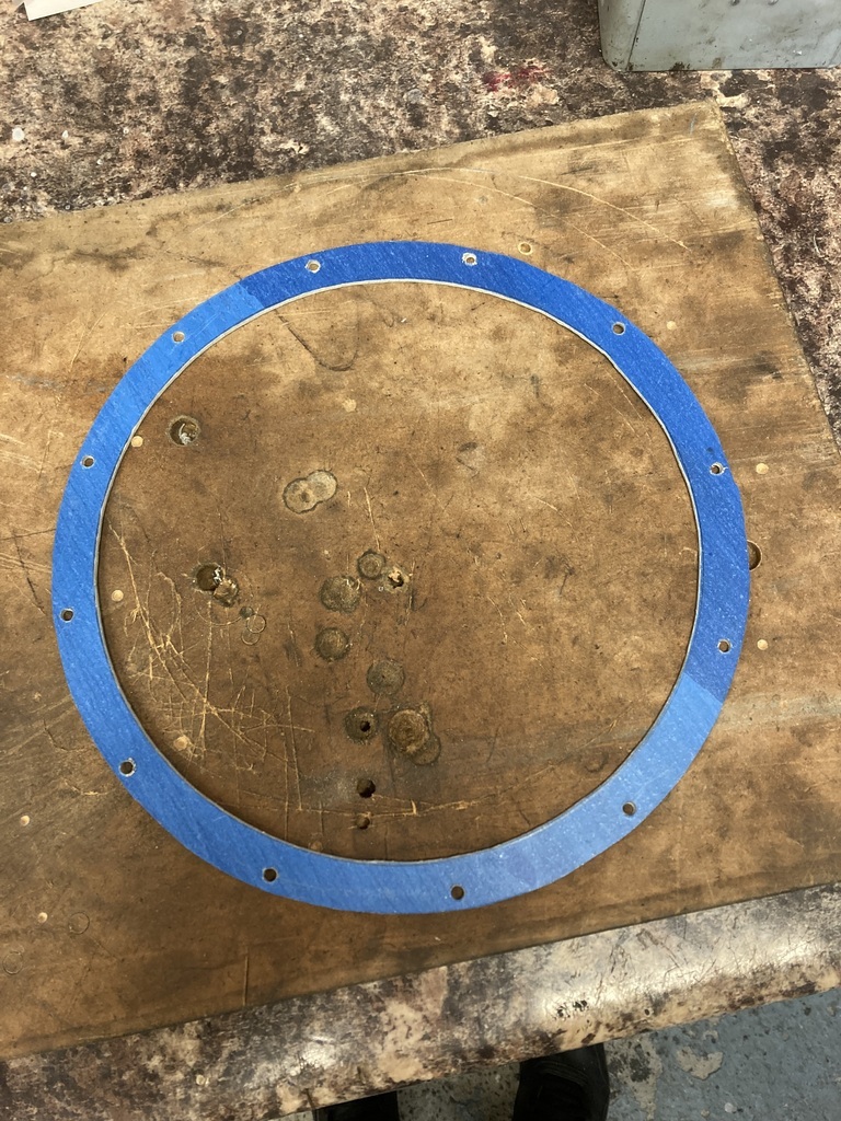 Time will tell if it all holds pressure. 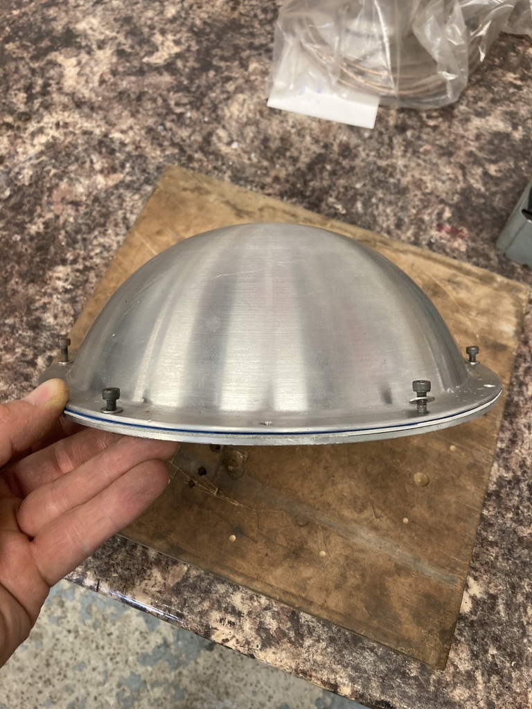 |
| |
|
|
Enbloc
Part of things
Posts: 367
|
|
|
|
Very nice job! Love these, where did you order them? Thom As mentioned, Torques UK. They only trade on EBay as far as I’m aware. I've just used Torques for the same job on my Humber. Same black fittings. Good company. The flatty is coming on great, looking forward to seeing how it works out. Thanks. Me too! ODD BALL "O" ring fitting, I used one recently for a breather fitting, TBH I was dubious about it for a fuel HP fitting, Aeromotive, being a US company would be careful about Litigation in case of failure, they must be happy with them!! 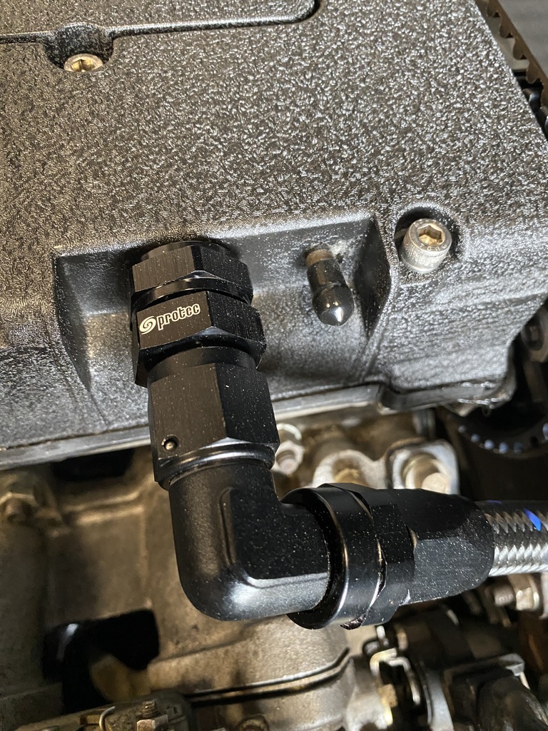 Yes, it’s odd they chose this style of fitting as the “standard” with aftermarket fuel parts seems to be NPT. Which is what all the other parts are and the other in tank pumps I looked at. |
| |
|
|
Enbloc
Part of things
Posts: 367
|
|
Jun 28, 2023 22:40:50 GMT
|
The fuel pump all buttoned up in the tank meant I could think about running the fuel lines, feed and return. I decided to return to -6 AN style fittings from Torques on EBay. I didn’t want jubilee’d barb fittings especially on the pressure side and also the Aeromotive pump took an odd ball ish -6 straight thread O-ring seal fitting. The days of only having luminous red and blue fittings with shiny stainless braid line are long gone. I opted for black fittings with PTFE/Teflon lined braided fuel line with a black nylon braid over that. Being PTFE/Teflon lined meant ethanol resistant and no ‘sweating’. 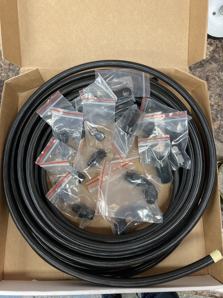 I even treated myself to the proper tool for opening the braid up. It was most certainly worth it as well. 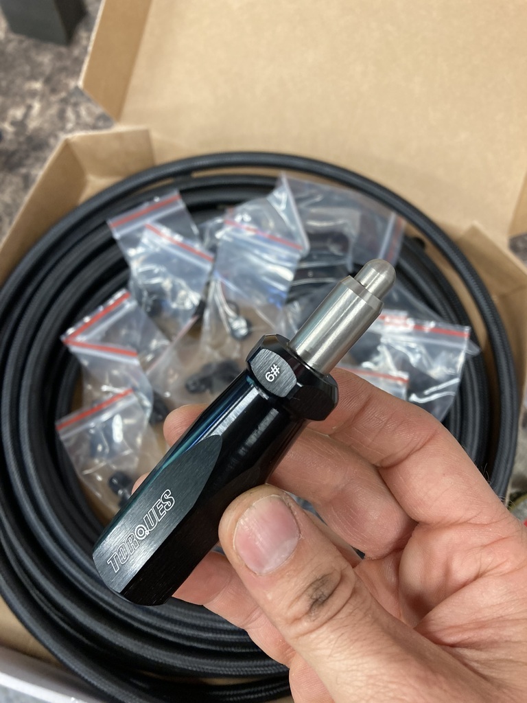 I had the the fuel filter and pressure regulator to mount. As previously mentioned the fuel pump can supply either a carburettor or injection system with the correct regulator. This return style fuel regulator from Holley I chose can support both with a simple change of the internal pressure spring. 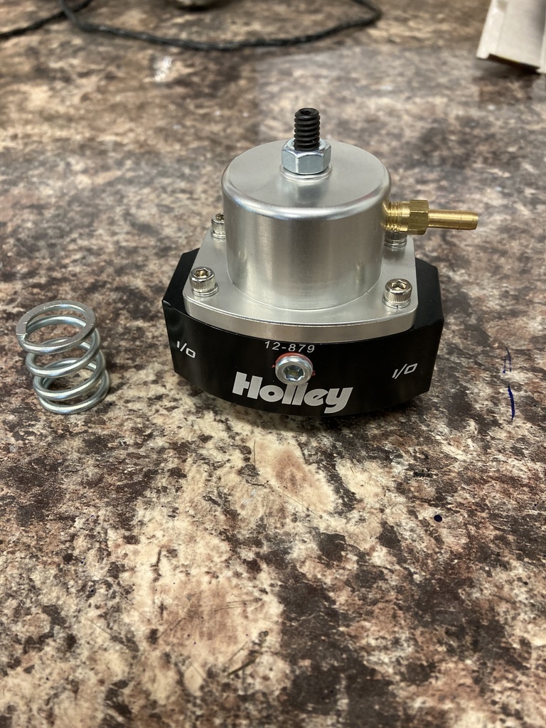 With it there in front of me I might as well change the spring over before it gets forgotten. 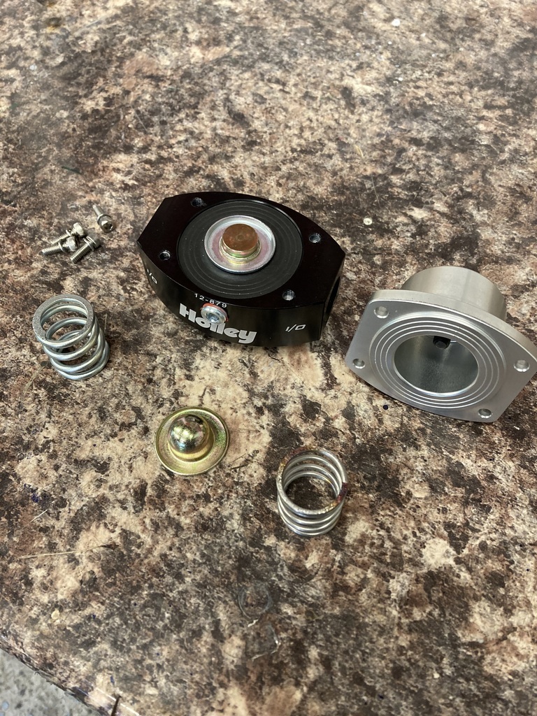 A straightforward job and now onto finding it a place to live in or around the engine bay. I got sidetracked at this point and started messing with the fittings I’d got for the Retroject throttle body. The in and return are positioned right next to the water outlets on the head so space was limited. Torques did these shallow NPT to -6 banjo fittings which were a real help. Problem was I couldn’t squeeze the two next to each other. 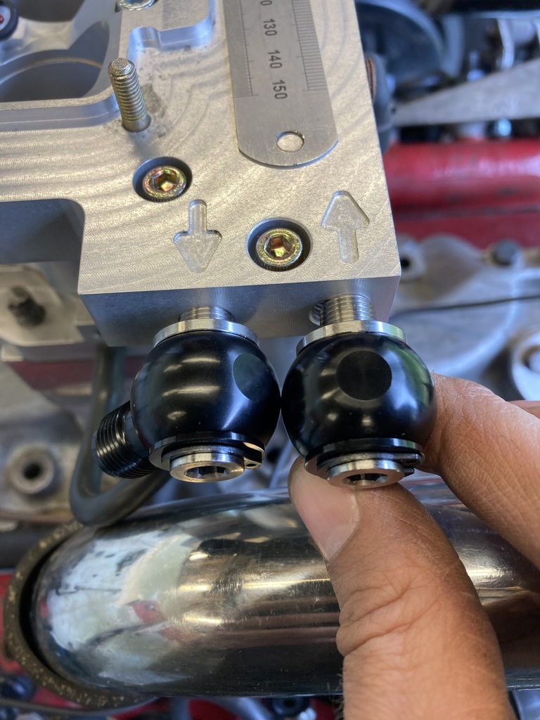 While in the area I remembered this. 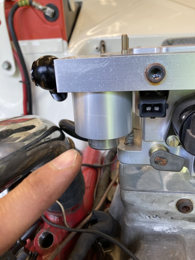 That’s a built in, preset fuel regulator with a return! Doh! I wouldn’t need the Holley at all. One less item I need to find a home for at least. The post pump filter could go anywhere before the throttle body so I chose an empty area of chassis rail half way down the car. 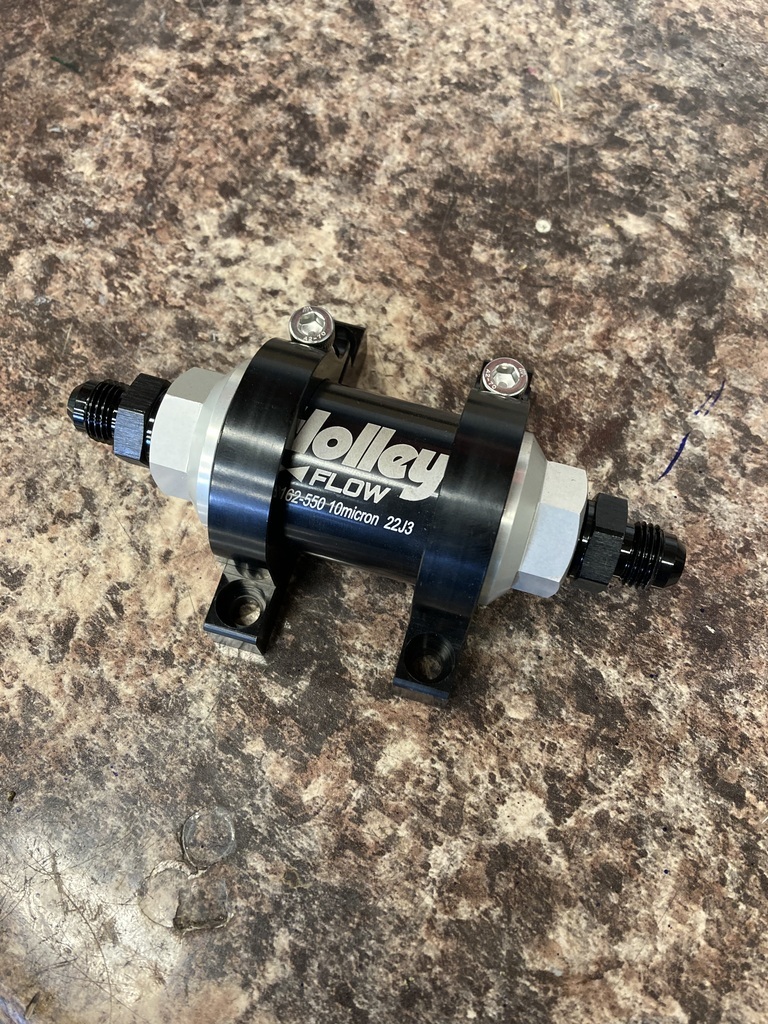 The brackets had the mounting ears but they also had these drilled and threaded holes on the backside. 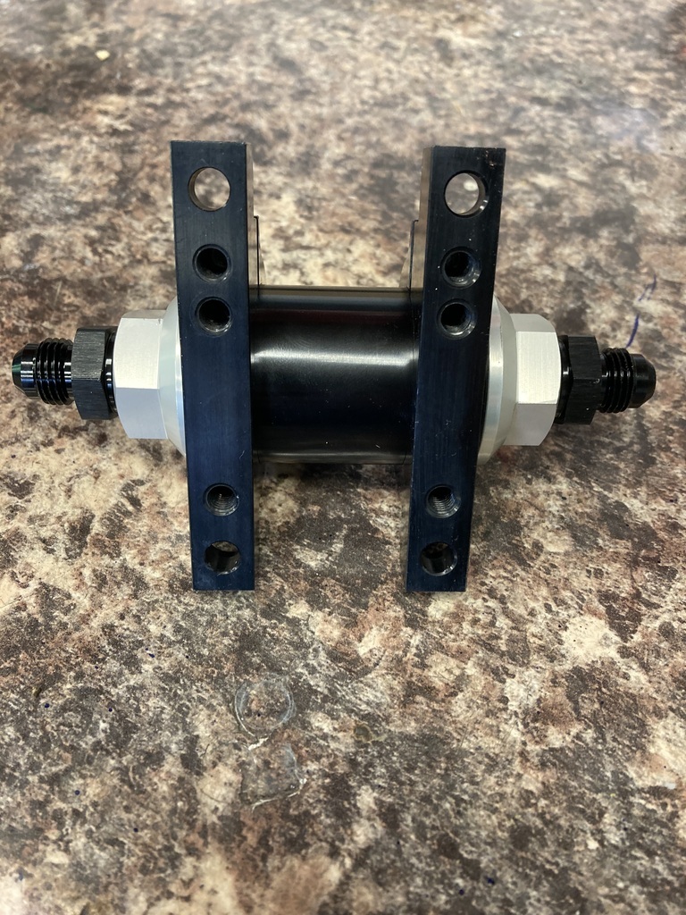 The threaded holes would make a much cleaner install so I cut the ears off as they were surplus to requirements. 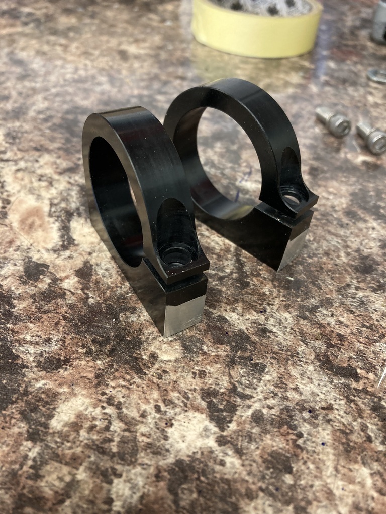 Mounted up in its new home… 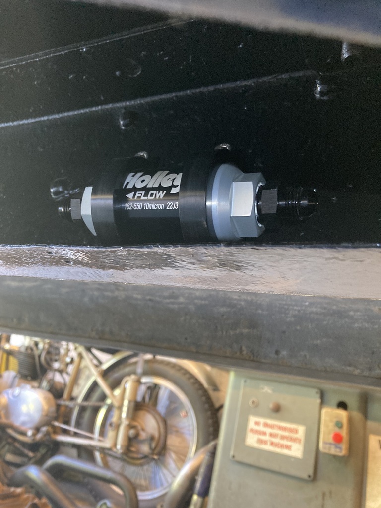 4x M6 fixings was a little excessive for what it was so it got 2. 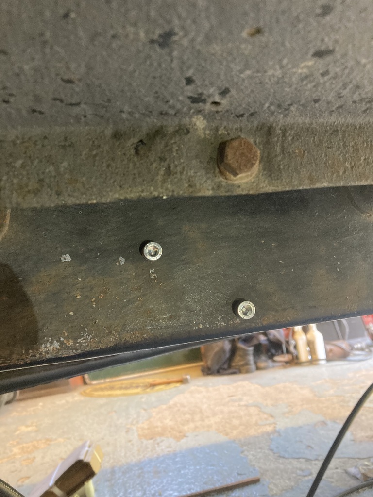 I ordered these -6 hose clamps. They are bolted together with a securing bolt but no means of mounting. 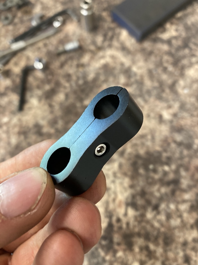 What I did was drill out the threaded half and replace the cap head screw with a longer M3 cap head. 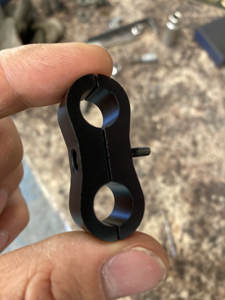 I put rivnuts in key locations along the chassis for the clamps. 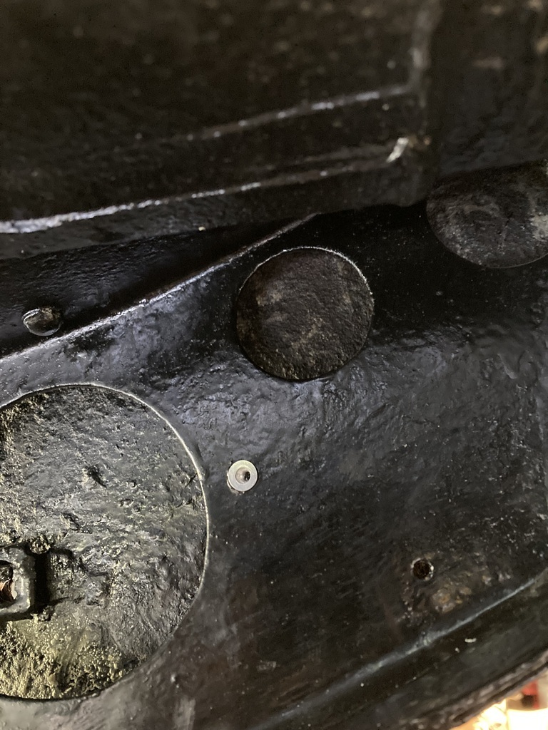 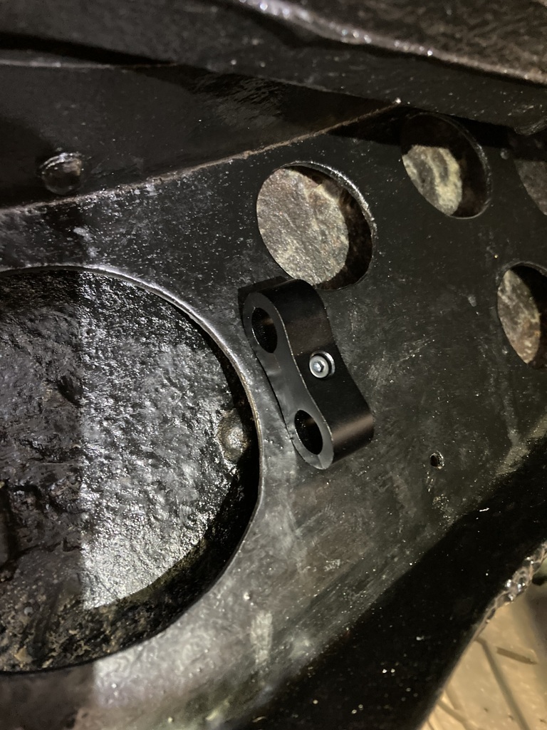 The plumbing was surprisingly simple as the only break in the two runs from front to back is the filter. The return line run is one continuous run. 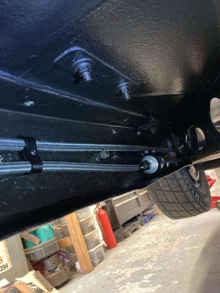 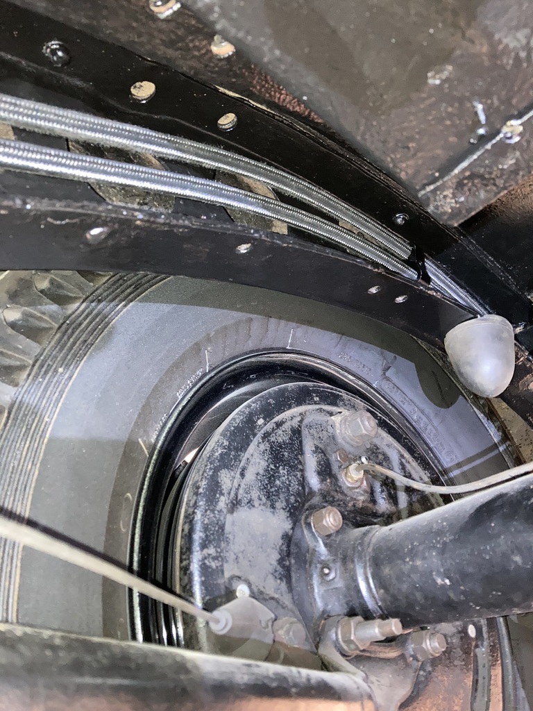 I was feeding the return line through the chassis at the front when the length of line looped on its shelf. Naturally, I just pulled it as you would with rubber hose to untangle it but instead there was loud cracking sound. 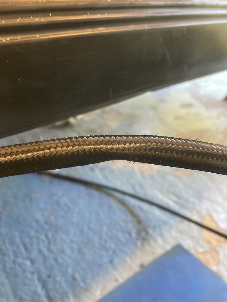 This was what I was left with and of course it was right in the middle of the car in that continuous return line length. Not knowing what damage it had done internally I had no choice but to cut it out. Luckily, a quick measure up showed I had enough length left on the roll to rerun the return line and what I had already run was plenty long enough to do the last section from filter to throttle body. Here’s what it looked like after I’d cut it out. It had a healthy kink in it but I don’t think it had split open, which is what I was expecting. Lesson learnt, PTFE/Teflon not springy like rubber! 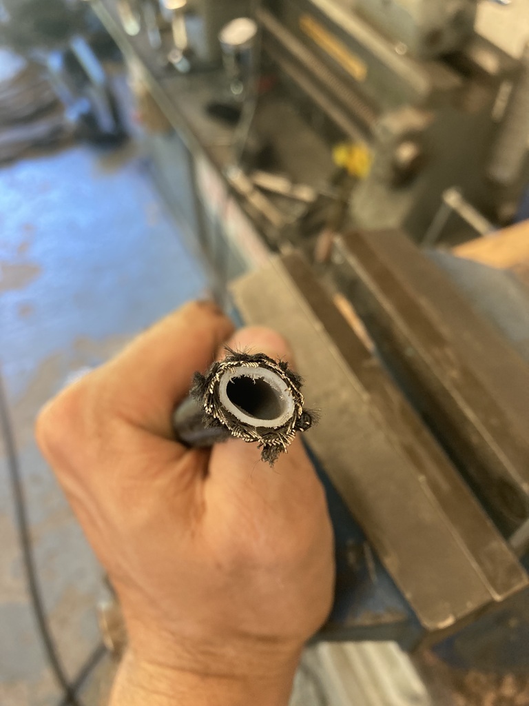 |
| |
|
|
Enbloc
Part of things
Posts: 367
|
|
Jun 27, 2023 21:08:57 GMT
|
Oh that's painful to read! Hope it's sorted now. Clutch disc is still stuck.If that is the problem, of course. Can't do much about it till the engine is running. Try the Coca Cola trick. Spray it in the bell house in rather large qty especially above the pressure plate. Wait a while and wiggle it. Quite often it frees then. Thom Sounds sticky. |
| |
|
|
Enbloc
Part of things
Posts: 367
|
|
Jun 26, 2023 18:28:49 GMT
|
A lot of loose end tieing and finishing off work going on. I finally got my clutch line back which meant I could connect and bleed the clutch and also the brakes as well. 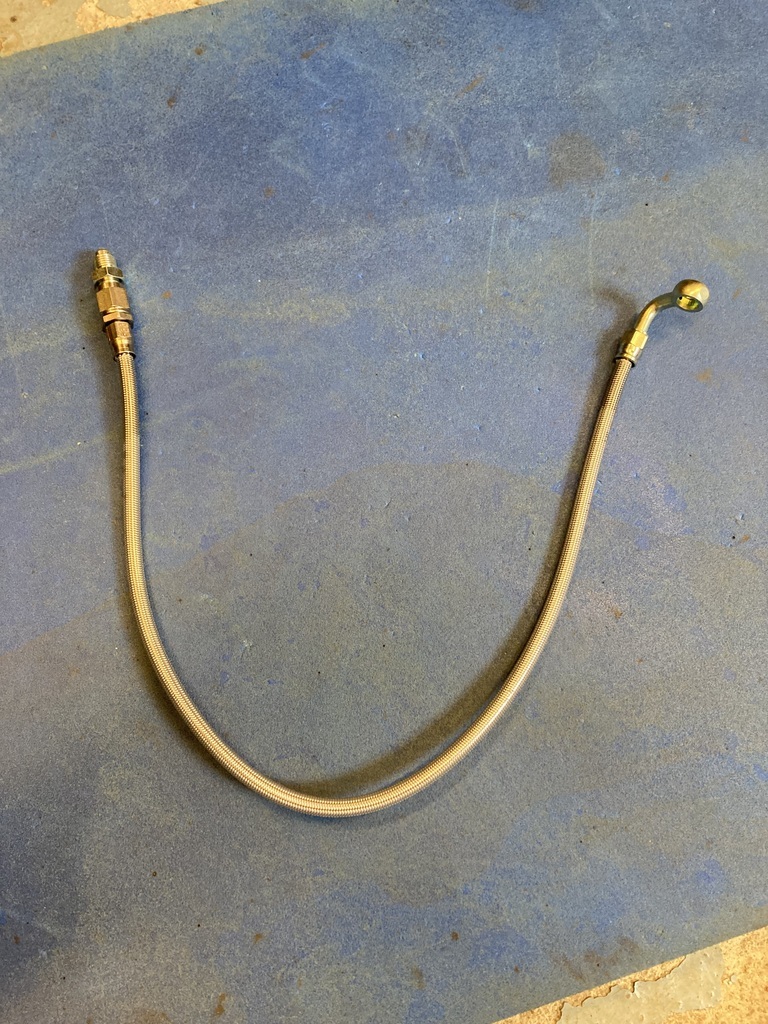 I First gravity bled it… 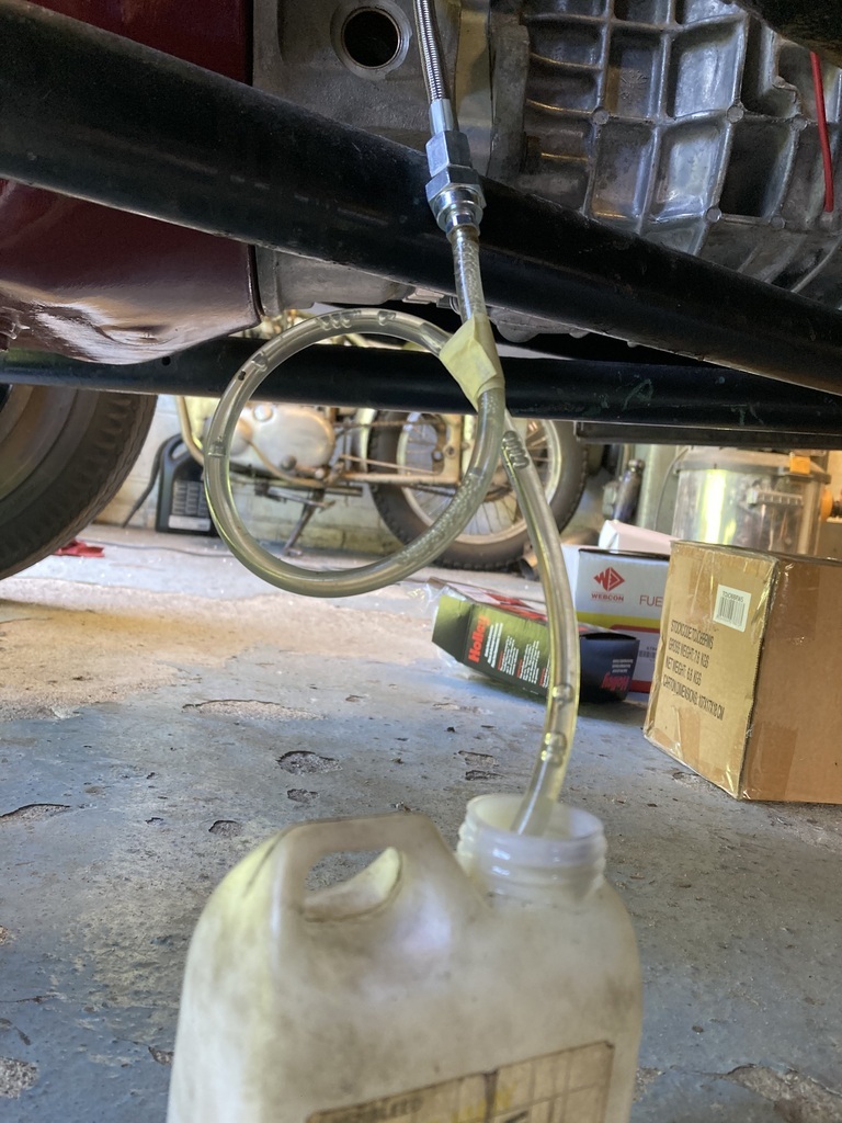 … and then pressure bled at 5 psi. 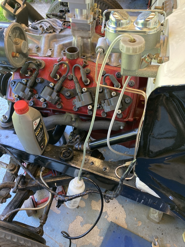 I now had a pedal so I needed to work out the release point of the pressure plate to set a stop on the clutch so it doesn’t over stroke the internal slave. This is done by jacking the rear of car up and putting it in gear. A helper then try’s to turn the rear wheel while the clutch pedal is depressed. When the rear wheel releases you’ve found your clutch release point. Well, I had the clutch pedal to the floor and even beyond the floor with the floor board removed and the clutch didn’t seem to be releasing even though I could clearly see the pressure plate moving a significant amount through the inspection hole. 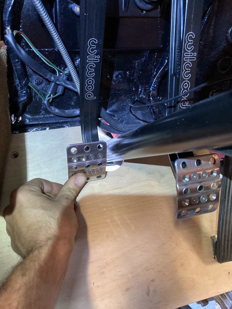 At the time I assumed I didn’t have enough fluid volume from the master. I was using the old 3/4” from the previous pedal set as a starting point. I swapped over to a .825” master, the biggest I could in the this style master, and bled that one. Exactly the same! Full pedal stroke, massive movement on the pressure plate and still the clutch wouldn’t release. At this point it was decided that something else was at a play here. The gearbox was first to get prodded as it was possible it had got hung-up on itself. The cover plates came off getting access to the shifter rails and the gears themselves. 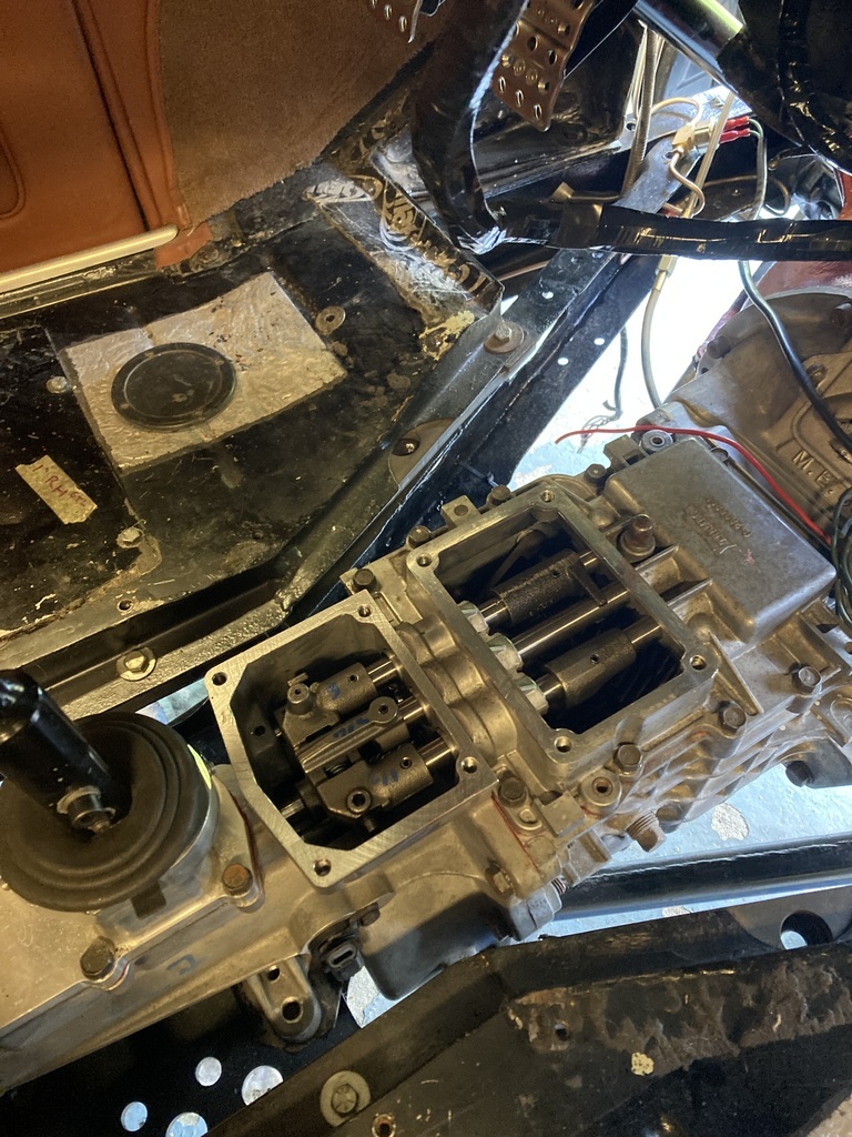 The TKO’s have a habit of getting the shifters stuck, that inferior 3-rail design (Been there, got the t-shirt) but all was fine and nothing else obvious could be seen. I then tried to turn the engine over with the long handled ratchet and solid! Would not move one bit in either direction yet it was spinning over on the starter motor only a few days previous! 🤷♂️ I small amount of panic was setting in at this point that something had gone wrong with the motor but logic dictated that it was still a fault with the gearbox. At a complete blank I dipped into the Google-Foo for anything and surprisingly was presented with multiple results pertaining to stuck TKO’s. It seems that another quirk with the TKO’s is that after being stored dry and/or being shipped that the synchros can eerr.. get out of sync or stick locking the ‘box up The remedy is to simply rattle the input shaft back and forward which would usually free off everything . Great. If you haven’t got an engine bolted to it. 🙄 My ‘box had been sitting a good 6 months, probably more, at this point since I assembled it and had been dry as I’d yet to fill it with ATF. I went back in the garage late in the evening to try a few things like unsticking synchros but you can only access 3 of the 5 synchros from the access hole and nothing worked. At 1:30am I looked at the engine, thought to myself it’s not actually that far off being removed. By 2:30am I had it out and back in. 💪 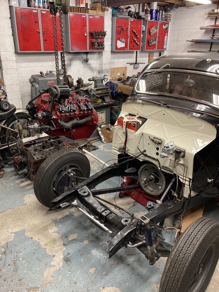 As soon as the engine popped off the gearbox it turned fine and I got ahold of the input shaft it also turned fine. Huh? Rejoined the two and everything turned again. 🤔 I think splitting the two had released whatever was binding. The next day a friend came round and on relaying the story I went to turn the motor over and it was stuck solid again! I’d been turning it over by hand only a matter of hours previous! I kinda clocked that I could get every gear apart from 5th, which is buried deep inside the tailshaft. With said friend under the car rattling the output shaft via the prop it clunked into 5th and the engine released again. So it seems that the 5th gear synchro is sticking and causing all the issues. I made sure to dump a couple of litres of ATF in this time and turn everything over and it hasn’t done it since. Would the clutch release now with the locked gearbox tangent out the way. No.🤬 Friend then said, “is your clutch disc stuck?” 💡 🤡 |
| |
|
|
Enbloc
Part of things
Posts: 367
|
|
Jun 21, 2023 10:34:41 GMT
|
Your turbo feed suggestions look right to me. Restrictor in the oil feed line at the turbo end and make the drain as big as you physically can. Thanks. What turbo is it? Generally a restrictor is needed for ball bearings, but no restrictor for journal bearings. The two large holes are indeed for water cooling. For most turbos water cooling is one of those things intended to make them last hundreds of thousands of miles driven by people with no mechanical sympathy. You could go without it if plumbing it in proves difficult. The oil usually provides sufficient cooling. The water is only there to prevent the oil coking up after the engine is turned off with the turbo still glowing red. Its a chinese GT35/GT3582 copy. Not sure on the bearings, I think journal. Thats answers my next question! I could, if I had to, plumb for water but don't want the extra plumbing and faff. |
| |
Last Edit: Jun 21, 2023 10:40:14 GMT by Enbloc
|
|
Enbloc
Part of things
Posts: 367
|
|
Jun 20, 2023 16:33:34 GMT
|
Looking at turbo plumbing today. Can any turbo geeks confirm I’ve got things right? I’ve got 4 holes in the centre housing. Top hole, looks 7/16 UNF. oil feed? Restrictor needed?  Top hole is flanked by two larger holes, look 1/4” NPT. Are these water coolant? 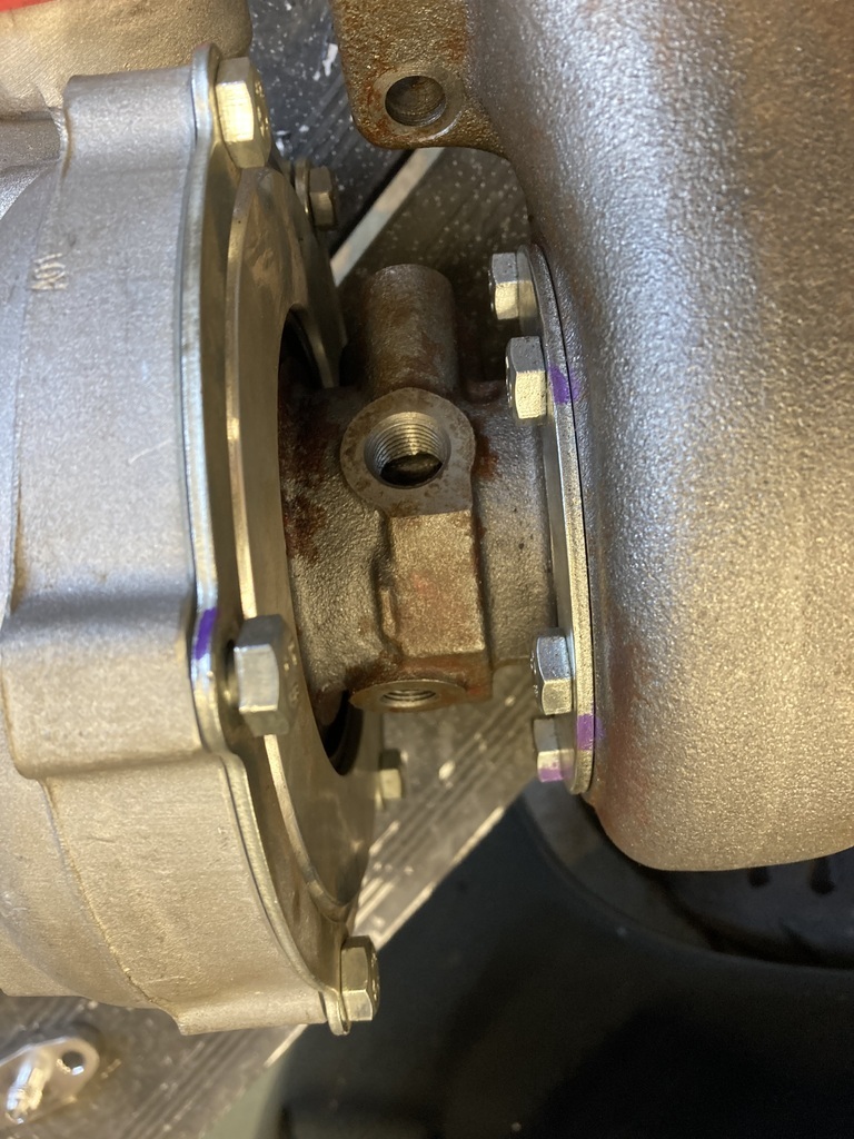 Bottom hole that has the flanged boss fixing. Drain back? Is -10 a good size for this? Thanks. |
| |
Last Edit: Jun 20, 2023 16:37:55 GMT by Enbloc
|
|
|
|