|
|
|
|
|
Nice job on the amp, at least you can actually see the components without the need of a magnifying glass! Think you might of got the valves just at the right time... Thanks! Yes I reckon a couple more days and I wouldn't have got the valves delivered. I have mixed feelings about using them, but at the end of the day they're 40+ year old NOS from the Soviet era and predate this current day rubbish that's going on. |
| |
|
|
|
|
|
|
|
|
|
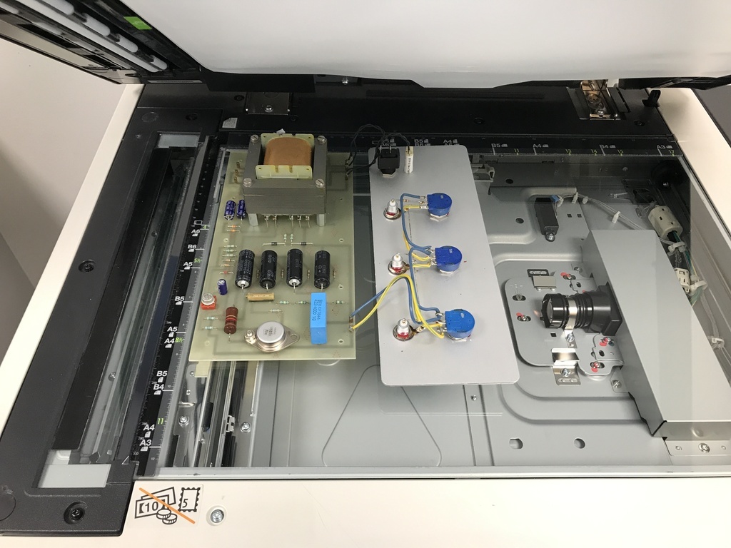 Everyone takes their 1000V power supplies apart and photocopies them, right? I thought it would be a cunning way to get a trace of the tracks on the PCB, then I could work out the circuit diagram. This is what I got: 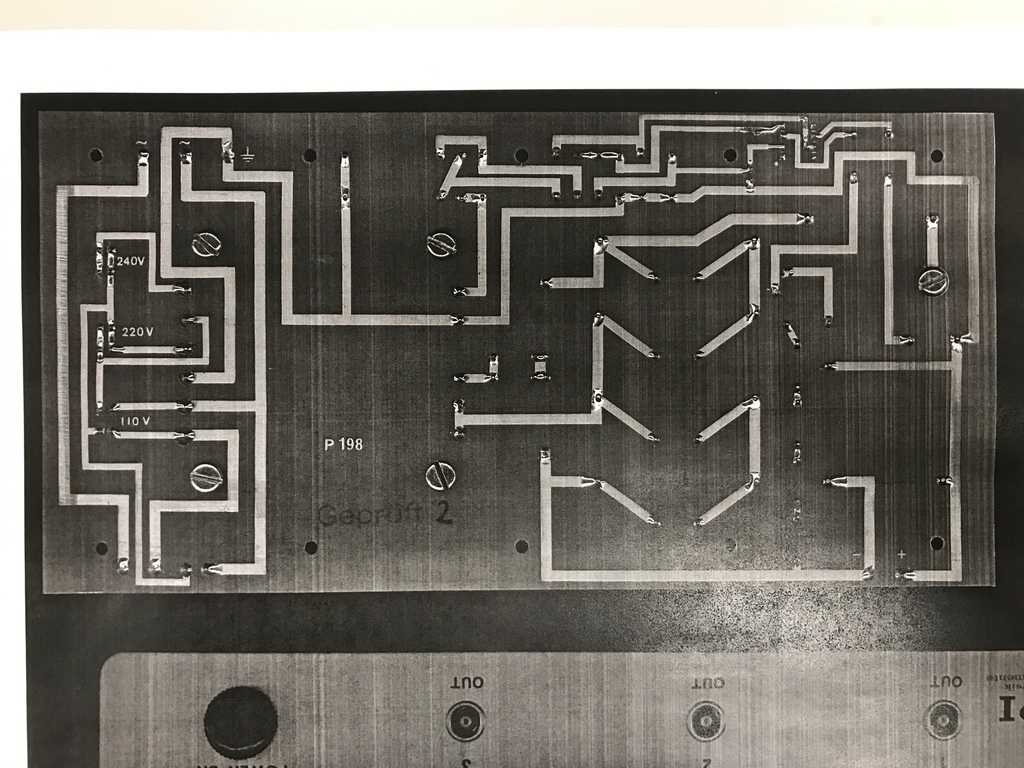 First thing I could do was work out which line was 0V, or, in this case, earth. That helped me work out the transformer outputs so I could stick a voltmeter on and measure the output voltages. Then I could start drawing components on the PCB tracks to make up the circuit: 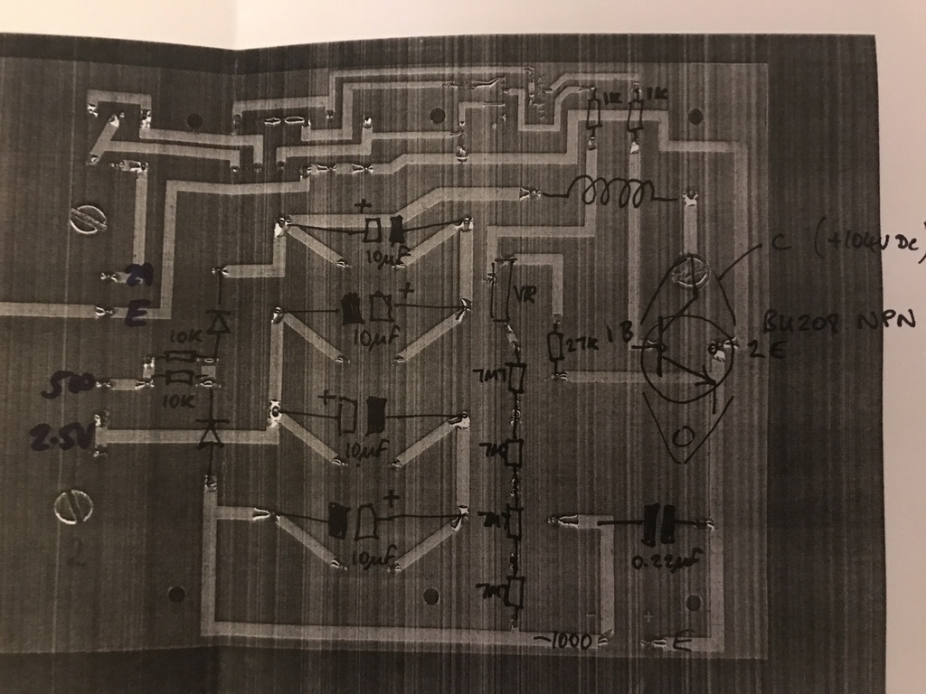 So from there I can start to work out how it’s different to a normal DC boost circuit. This is a normal one: 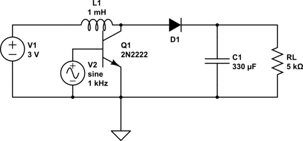 The main difference seems to be that the capacitors are on the other side of the inductor and there’s the extra diode down at the bottom left. I’m pretty sure if I were to put a diode on the right hand side of the inductor (pointing right) and the capacitors in series to earth, it would give me +1000V DC. I’m tempted to add on a break-out board to do this. |
| |
Last Edit: Mar 7, 2022 22:52:33 GMT by Jonny69
|
|
|
|
|
|
|
I did that ^ at lunchtime with a stick-on thing I made: 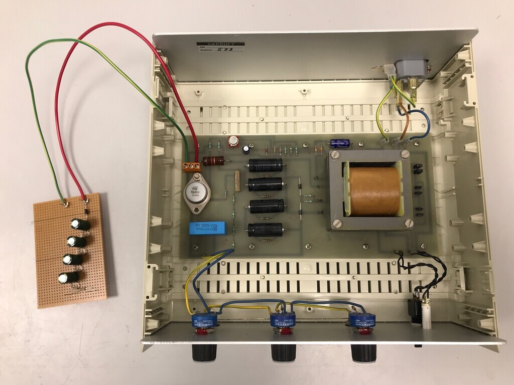 Took some brave pills before I switched it on. Nothing exploded, but it didn't work and I did a sad. Plan B, I think, is to try turning the existing capacitors and diodes around. |
| |
|
|
|
|
|
Mar 10, 2022 15:28:14 GMT
|
Small modification on the preamp. It does hum a bit. I think it's picking it up from the heater wires, which happens when you have relatively high AC current running near other things. I shortened a couple of wires and lifted what I could as far from the heater wires as they would go, but no joy. On some amps, you twist the heater wires together to remove the tendency to create hum. I can't do that on this because one side of the heater wiring is grounded through the PSU chassis. Instead, I've opted to convert the heater circuit to DC, which should mean there's no hum pickup. First took a pic of the original wiring, so I don't forget how to put it back if I need to: 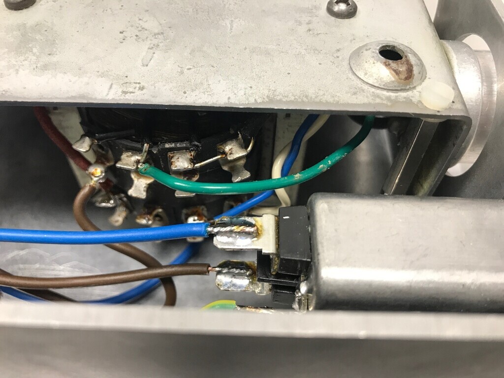 Then fitted up a small vintage bridge rectifier to the underside of the PSU chassis and an old Phillips 150uF capacitor from maybe the 1960s. I connected up the rectifier valve and decided to have a look how smooth the new supply was. It wasn't very, so I started adding more capacitance by piggy-backing capacitors until it looked satisfactory. I could have made my life easy by using a modern capacitor, but the spirit of this build is very much to use old components where I can. The disadvantage of old capacitors is that that are significantly larger. The one I've used is 25mm diameter and about 50mm long, compared to the modern one I've got which is maybe 15mm diameter and about 30mm long. So I had to make a P clip to mount it up like so: 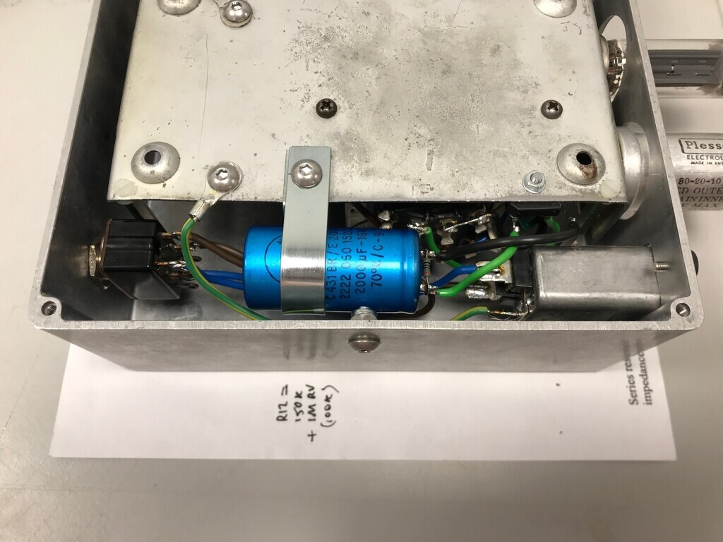 This was a proper faff. To get the bolt in, I needed to take the earth off so I could get a spanner on the nut. To get the capacitor in, I needed to take the other end of the earth off and take the IEC socket out, then do it up with everything disconnected, then put it all back. Still, done now, fingers crossed it works. |
| |
|
|
|
|
|
Mar 17, 2022 11:52:06 GMT
|
New project: Mullard 3W class A valve amp! 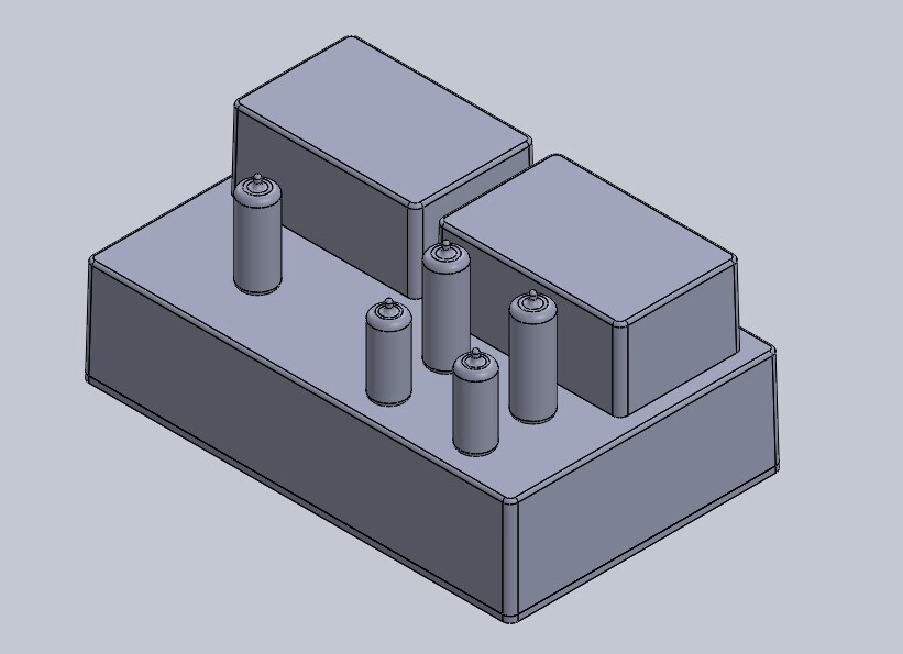 Ok, I don't seem to be able to help myself. I have two perfectly functioning high-quality amps, so I definitely don't need another amp. But I do need to satisfy my need OCD need to pair things up and finish projects. I don't like loose ends. One loose end is the single output transformer I got for the unfinished AA battery-powered valve amp which I have decided will not work. That transformer came from RS about 10 years ago and it turns out they're still available with the same part number and spec. So I got another. 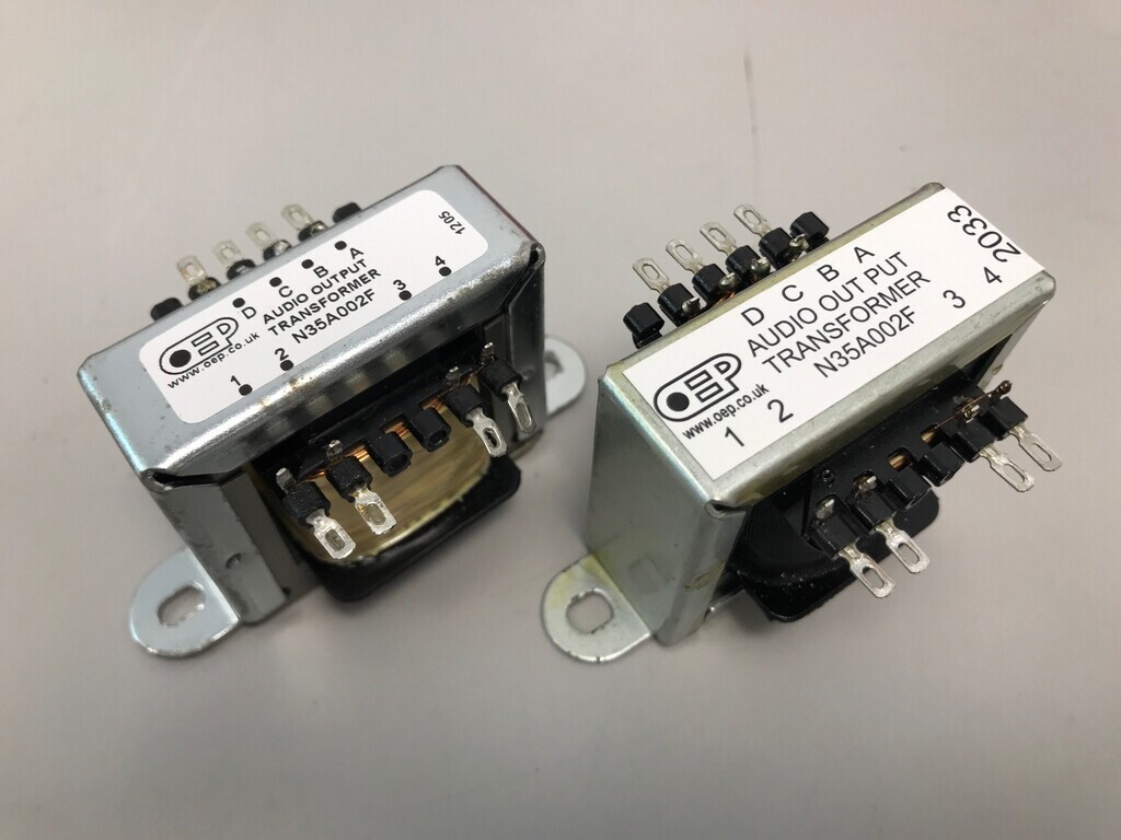 The transformers have me a bit unsure what they're going to be like. They are 3W output-stage audio transformers from OEP, for a single EL84-size valve (i.e. a small one) in Class A, with multiple taps for different valves and different speaker impedances. I think they are just audio-grade output transformers but maybe not hifi quality. They weigh about 375g each, compared to the ones on my 25W amp which are well over a kilo. I assumed most of that difference was because of the difference in power handling, but OEP also do some hifi transformers for a single 3W valve which are 1300g each. That's quite a difference, so I'm going to allow some flexibility in the design of this one to potentially accommodate a change of transformers at a later date. So I think that means (in no particular order): 1) Where the pre-amp has both left and right channels squeezed on the same boards, I think this amp will have separate left and right boards as modules. If I change my mind later I can simply pull the modules out and modify them. 2) If I'm going to upgrade the transformers later and they are going to end up significantly bigger, it might make more sense to do a baby push-pull amplifier. That needs a bigger power supply so I'll start now with a bigger power transformer than I need as the cost is about the same. 3) Let's say this doesn't work out, it'll make sense to spend a bit more on an old branded transformer from back in the day. It'll be more suitable for other projects and have better resale value than a new one or an unbranded one some eBay seller has parts-raped from another piece of kit. That helps determine the spec: -EL84 valve output stage, for availability of parts. I've gone for 4 matched 6P43P-E / 6П43П-Е (EL84 equivalents) coming from Ukraine, fingers crossed. Sounds mad at this time but the seller was very grateful for my support and patience. Our continuing use of eBay during this time is a valuable income for Ukrainians. -EF86 valve input stage. Using 2 matched Soviet 6J32P / 6Ж32П as before, which sound fantastic to my ears. Coming from a different seller in Ukraine. -In my head I want this to be compact, like the pre-amp, in a sturdy, cast alloy case. -Recessed valves at the base, but not as deep as the pre-amp ones (which really need to come up a bit). -One input with volume control. -No tone control. |
| |
Last Edit: Mar 17, 2022 17:42:15 GMT by Jonny69
|
|
|
|
|
Mar 17, 2022 12:02:31 GMT
|
For the circuit, I sort of fancied trying one of the GEC circuits from An Approach to Audio Amplifier Design. However, I think I mentioned in an earlier post that the circuits are a bit vague about their power and transformer requirements and are generally a bit more complicated. This is the GEC 5W amplifier: 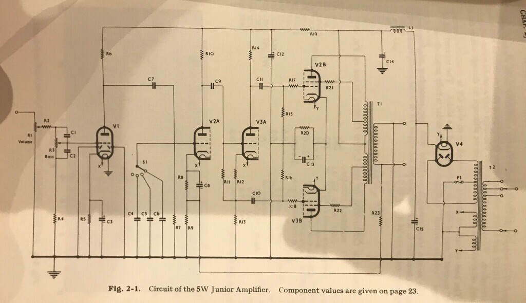 Whereas even after stripping off the tone control part of the circuit, the Mullard circuit is still simpler. With tone control: 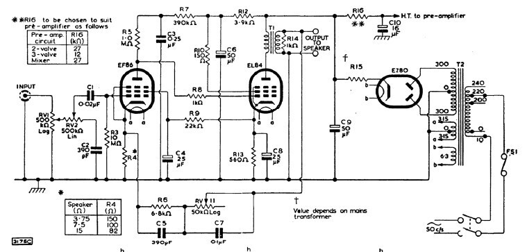 Without: 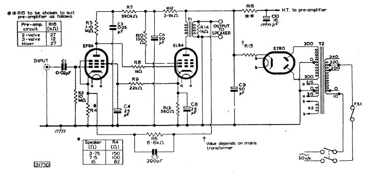 Additionally, the Mullard valves and equivalents are FAR easier to find. So that's that decided. If I'm using an old style transformer, it'll be set up for a valve rectifier, so with that in mind, here's a quick visualisation in CAD while I'm watching the all staff comms at work: That's using a Hammond 1550J encolsure which I used on the pre-amp. A Hammond 1590T covers the two output transformers. At the moment there's a second one covering the power transformer but that's subject to clearance, so might have to use a bigger one. EZ80 rectifier valve on the left hand side. EF86 valves at the front, EL84 valves at the back. |
| |
Last Edit: Mar 17, 2022 12:03:32 GMT by Jonny69
|
|
|
|
|
Mar 17, 2022 12:29:39 GMT
|
Or potentially using the smaller Hammond 1550G enclosure with the EZ80 sticking out the back: 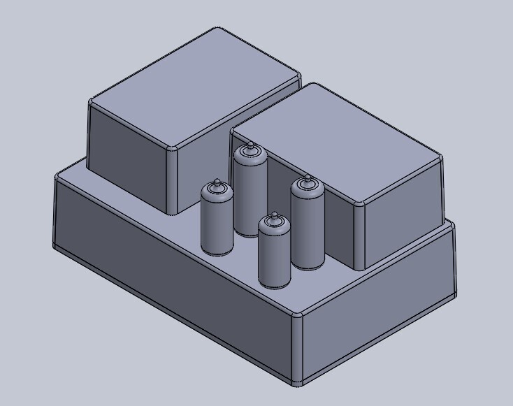 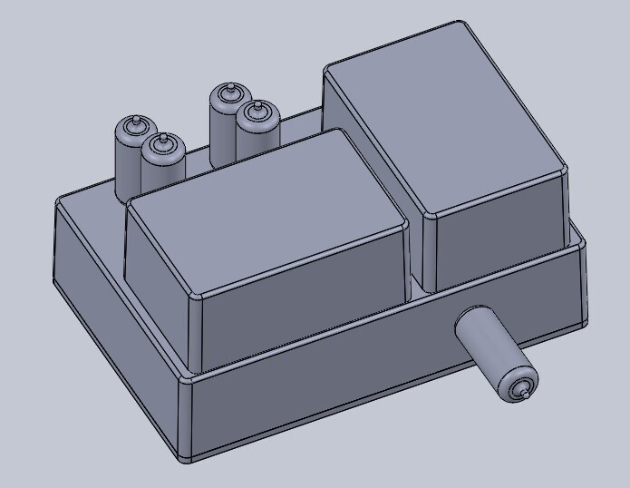 I think I'm going to struggle to fit it all inside like that though, so will probably go for the bigger case. CAD has its uses... |
| |
Last Edit: Mar 19, 2022 22:08:53 GMT by Jonny69
|
|
|
|
|
Mar 18, 2022 17:48:44 GMT
|
Excitement over delivered things. Interesting seeing a Soviet Yugoslav EZ80 next to a running Mullard EZ80. Internals are almost identical but the Yugoslavian valve is slightly longer. Other bits are the valve bases and spacers to set the valve height. 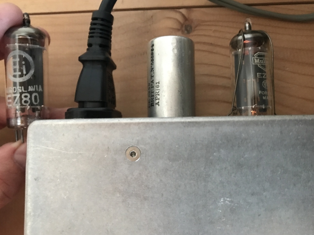 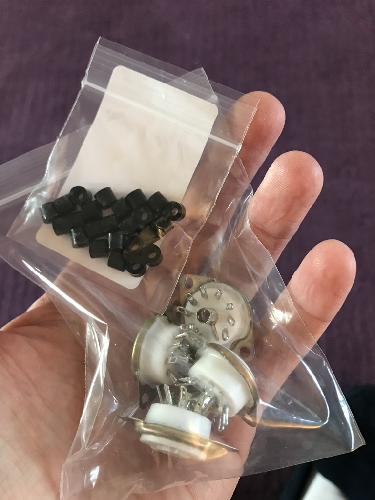 |
| |
|
|
Darkspeed
Club Retro Rides Member
Posts: 4,700
Club RR Member Number: 39
|
|
|
|
|
Thoroughly enjoying the thread, often contemplated building an all valve amp for my guitar. Maybe one day.
|
| |
|
|
|
|
|
Mar 19, 2022 19:46:30 GMT
|
Thoroughly enjoying the thread, often contemplated building an all valve amp for my guitar. Maybe one day. If you decide to build one, I’ve got the perfect circuit for you  Seriously though, I can help with getting the valves and which transformers to use. |
| |
Last Edit: Mar 19, 2022 19:47:07 GMT by Jonny69
|
|
|
|
awoo
Posted a lot

Posts: 1,504
|
|
Mar 19, 2022 21:18:07 GMT
|
|
Likewise, this is a great thread and effort. I’m restoring some old audio equipment and am in awe at your progress. You get loads done!
|
| |
|
|
Darkspeed
Club Retro Rides Member
Posts: 4,700
Club RR Member Number: 39
|
|
|
|
If you decide to build one, I’ve got the perfect circuit for you Seriously though, I can help with getting the valves and which transformers to use. That's a very kind offer and so tempting but at this time I have some larger point to point wiring projects that need my attention. The valves in those are all contained in cylinder heads  |
| |
|
|
|
|
|
Mar 20, 2022 17:08:35 GMT
|
Likewise, this is a great thread and effort. I’m restoring some old audio equipment and am in awe at your progress. You get loads done! Thanks! It helps having my lab at work where I’ve got a decent bench to work at, test meter and scope, soldering station etc. It makes everything much easier than working at home. That's a very kind offer and so tempting but at this time I have some larger point to point wiring projects that need my attention. The valves in those are all contained in cylinder heads Lol, well the offer still stands! |
| |
|
|
|
|
|
Mar 20, 2022 17:11:47 GMT
|
Had a quick look at what of the standard size Hammond boxes fit on the 1550J I used on the preamp. It’s looking promising. The 120 x 120 fits fine if I need a bigger one for the transformer and still leaves enough space to have the EZ80 rectifier at the front on display. 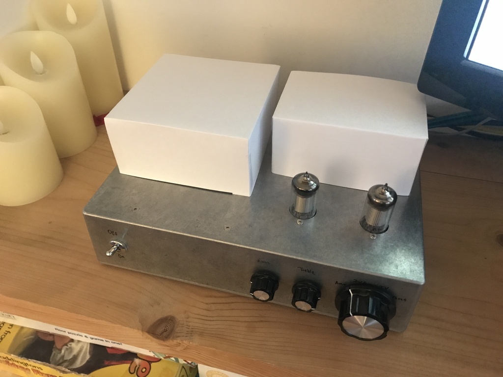 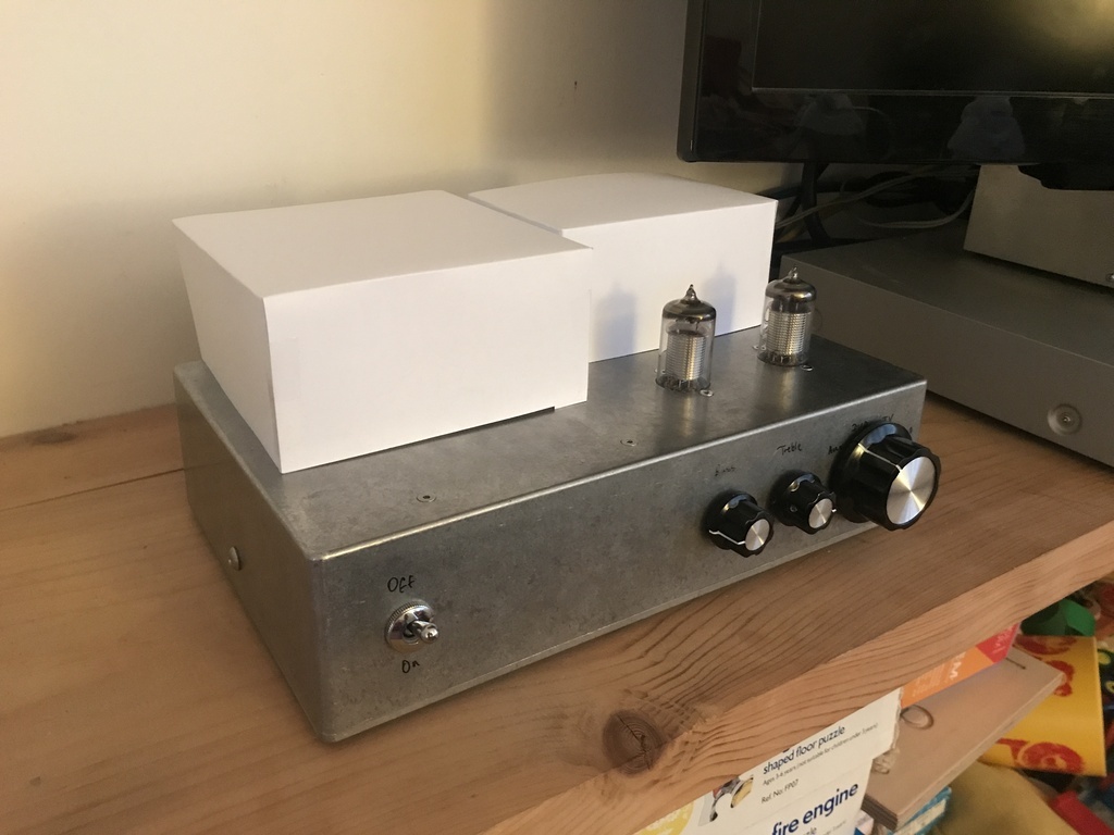 |
| |
|
|
|
|
|
Mar 21, 2022 14:07:57 GMT
|
Back to the 0-1kV PSU. I successfully flipped the polarity this lunchtime. I couldn't fully get my head around this at first, because it should have worked. What I really wanted to do was to flip the diodes and capacitors, but I couldn't do this because the 0V side of the board was coupled to earth. I wanted to see if I could uncouple the earth and run that side of the circuit high instead of low. So what I did was I broke the earth track underneath the transformer which connects the mains and circuit sides of the PCB. That gave me a floating 0V and relative -1000V DC. You wouldn't want to connect anything to it like this. I was looking for signs that I could couple the -ve side to earth and the '0V' would become +ve. It was reading -1000V and 0V, floating around 30V from earth so I didn't want to risk it. What I could see was now I could flip the diodes and capacitors without blowing anything 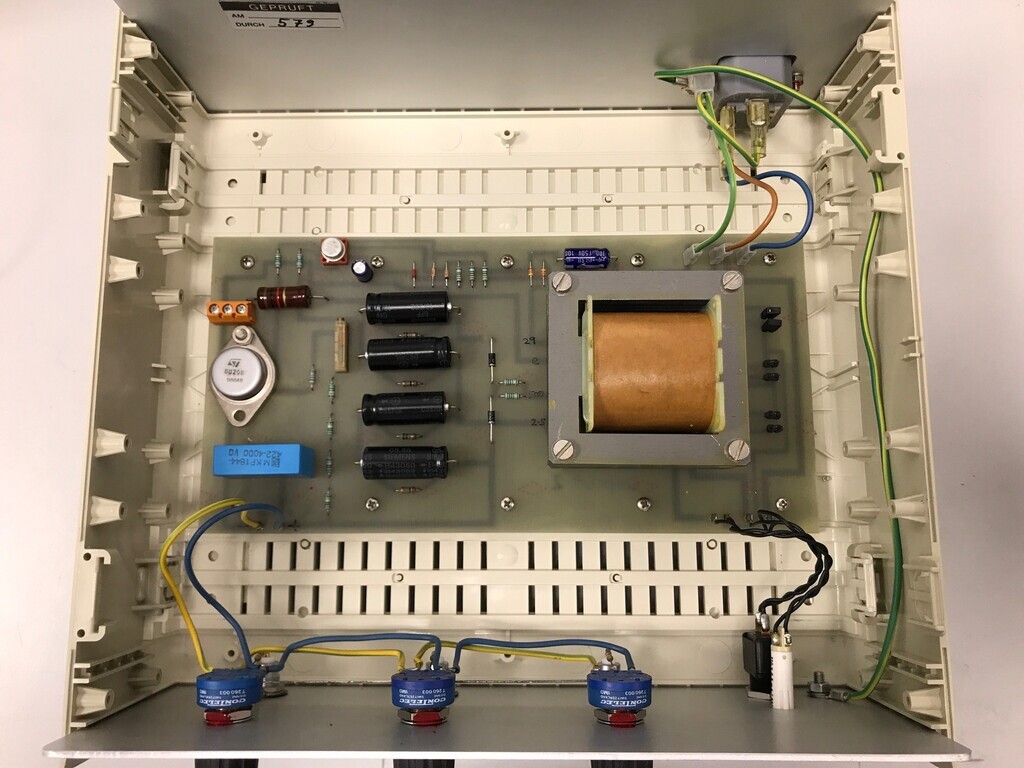 Result: 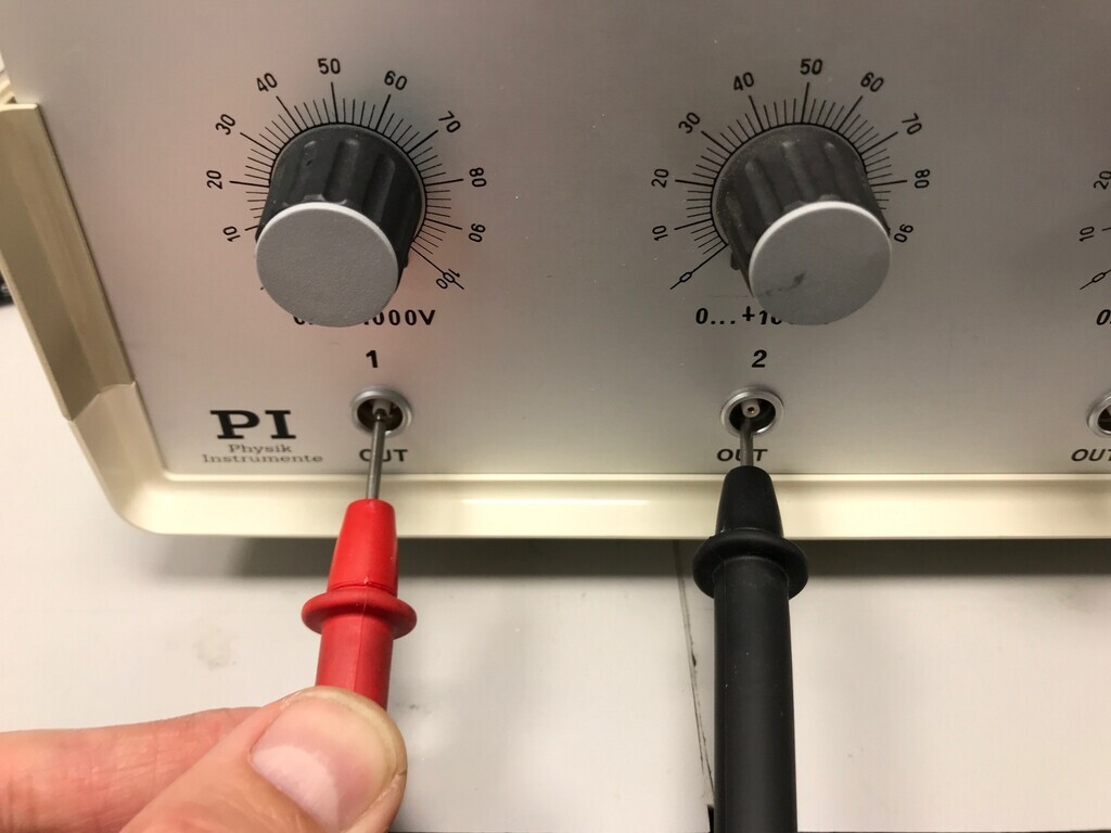 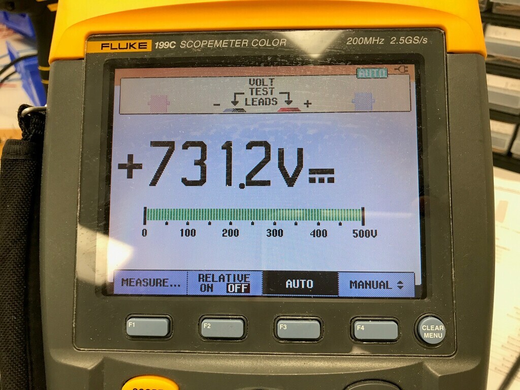 Result! That's 3x 0-730V DC. It shows as just over 1kV before the pots, so I think the 'missing' 270V is lost in the pulldown resistors. They are there to prevent the output momentarily going high on power-on or if the pot gets scratchy. That's it for now for this PSU. I'm going to drill in some 4mm sockets so I can use it properly but that's all it needs now. Maybe some analogue voltmeters if I can find some that go high enough. |
| |
Last Edit: Mar 21, 2022 14:08:41 GMT by Jonny69
|
|
|
|
|
Mar 22, 2022 16:09:05 GMT
|
Back to the 3W valve amp. The transformer arrived and it's a beast. Way bigger than I need for this but it'll work just fine. I'll have to use the bigger cover, so the amp is going to look something like this: 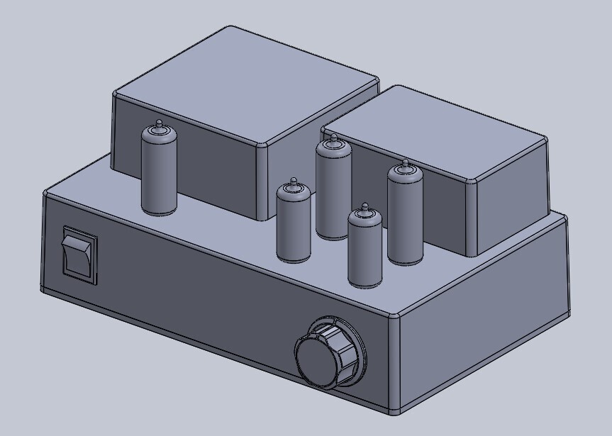 Quite enjoying a bit of lunchtime CAD to see how things are going to fit. It's a nice little paradox between old and new technology but also a great way to see what components I need to use. |
| |
Last Edit: Mar 23, 2022 7:14:27 GMT by Jonny69
|
|
|
|
|
Mar 24, 2022 23:21:56 GMT
|
Might as well take the opportunity to try out the new forum tool. The boxes arrived and I’ve drilled them for the valves and transformer covers. Did a quick mock-up with some spare valves for a sneak preview. 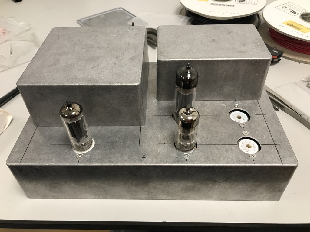 Interestingly, the ceramic valve base under the EZ80 is completely useless. It’s tight as **** but then wobbles about all over the place. I’ll have to swap it for a PTFE one. The 5mm spacers are bang-on though. I’m going to swap some into the preamp. |
| |
|
|
|
|
|
|
|
I added some 4mm sockets to the front of the 1kv PSU. This thing is done now and ready to use. I guess it could use a complementary high-current 6.3V heater supply… 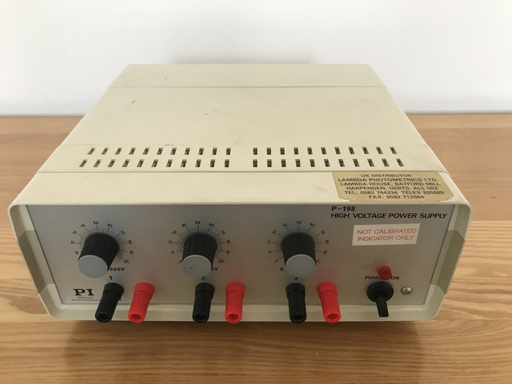 |
| |
|
|
|
|
|
Mar 30, 2022 16:44:19 GMT
|
Exciting that I might die doing this. It'll supply 100mA at 1000V which I'm pretty sure will kill instantly at that voltage. Best warning sign I've seen said "This machine won't just kill you, till cause you immense pain while it kills you" or words to that effect, probably applies to your power supply there! Great amp build. Getting the right look on the control panel with switch and knob style is always something that gets forgotten about until your looking at it finished thinking "nah, that not what I wanted"! |
| |
|
|
|
|
|
Mar 30, 2022 17:14:14 GMT
|
Thanks Gusman! I’m away with work this week so no progress other than sketching out where the components are going to go on the boards. But I did decide the Partridge transformer is overkill for this amp. I’ve got a smaller one on its way instead and the big Partridge one can wait for a future project (probably an EL34-based class A amp using existing components, maybe my own design this time). Pics of the transformer / PSU from the eBay seller: 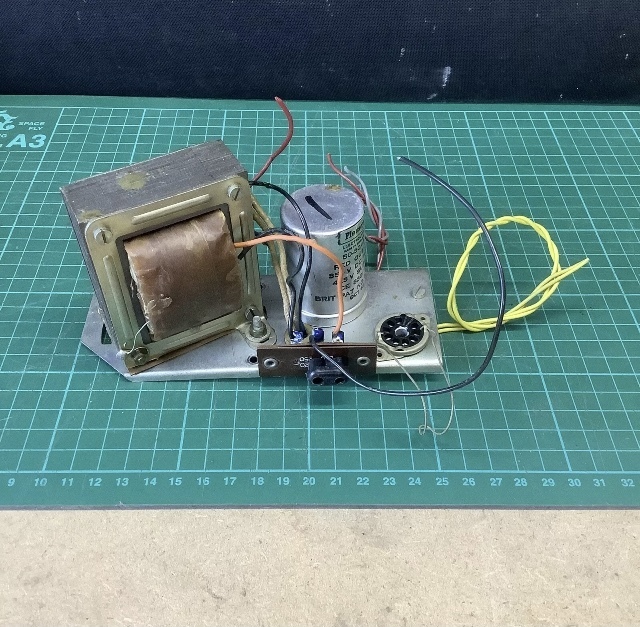 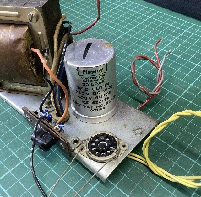 |
| |
|
|
|
|


